

smashtv
-
Posts
1,505 -
Joined
-
Last visited
Content Type
Profiles
Forums
Blogs
Gallery
Posts posted by smashtv
-
-
On 10/23/2020 at 9:41 AM, latigid on said:
Is it a two-layer board with green soldermask? Then no bridges are required.
No jumpers on my R4C and R4D pic based core layouts. My PCB layouts usually have an "R" designation to avoid confusion vs. the official layouts that usually had a "V" designation.
Andy is correct, except the ones John produces (modular addict shop) are black silkscreen, and the ones from my shop (midibox-shop.com) were green silkscreen.
John's also have some very slight differences with silkscreen (lot code for the pcb fabricator and UL 94 declaration) and soldermask (blind vias vs. exposed vias) but everything else is the same.
We used to call this one the "Core8", but in the years since it is more commonly referred to as "PIC Core".
Lots more specifics for R4D here: http://midibox-shop.com/mbhp_coreR4d.html
And for some of my other layouts here: http://midibox-shop.com/info.html
Also if you are building a SID you will need to terminate the CAN bus with a 1k resistor and a diode or it will likely either reset at random or get stuck in a boot loop. Plenty of info on that change here in the forum posted years ago.
Best Regards!
Tim
-
Hi all,
After ~15 years of designing/producing/distributing MIDIbox boards it is time to hand off production & distribution to someone who can do it better than me - John at Modular Addict.
He has most of the boards in stock and ready to ship now and the rest will be added to his shop soon: http://modularaddict.com/manufacturer/midibox
I will still be around the MIDIbox universe and I look forward to bit more time to focus on other things.
Best regards
Tim
-
4 hours ago, Molom said:
Any news on when the next boards might be available Tim? A quick heads-up, even just to say "I don't know yet" would be cool.
Official answer: I don't know. When they arrive I will put them up on the shop.
Unofficial answer: I have a few board runs in process and I expect another batch of 6582s in 10-16 days.
On 11/17/2016 at 1:15 PM, dreamer said:Too bad missed out on this. I still need a new main board. I hope it will get restocked.
Dreamer I did not forget about you but I used the boards I set aside for you and arumblack to replace a mis-delivered international order.
When the 6582 run arrives I will pull another set and try again.
Best regards
Tim
-
11 hours ago, Molom said:
Damn, looks like I just missed out. I am very keen to buy these boards sets too. Do you have any idea when you will have them again Tim?
It should be roughly 1 month. The fabrication run has been ordered and paid for but it's on a long-turn schedule to keep the price & quality level the same.
<not directed at anyone specifically> Please understand that I may not respond to many of the questions coming in via facebook/email/contact form that do not ask a specific question. I am getting hammered from all directions with "I want to build MIDIbox do you have boards" or "Will the xxxx boards be in stock the last week of December when I get my Christmas money".
Which MIDIbox? Is the last week of December when your school project is due? (inside joke for the other ancients
 )
)
These types of questions require a lot of back and forth dialog/time that could be better spent packing and shipping orders. </not directed at anyone specifically>
Best regards
Tim
-
IIc, DIO_matrix, DIN, and 6582 boards restocked.
Fabrication run in progress for the CORE_STM32F4 and DOUT boards due in around the 25th.
Sometimes life gets very busy. As always (~14 years!?!) I would give everyone fair warning if I decide to quit producing boards.
Smithy and I are working to set up a Euro shop that will speed things up and lower costs. We do not know when it will be ready and will not guess, so please understand that we will be working toward that goal instead of answering endless emails asking when it will be ready.
Sorry I have not had time to answer every email or any of the wild speculation about my demise :)
Best regards!
Tim
-
Hi guys,
dreamer and arumblack - splitting a set would work and I will do what I can to make this happen. Check your private messages.
Macotronic - I have never left the 6582 boards out of stock for more than a quarter, and I have never had a run of those boards sell in less than 2 months. 4-6 months to sell a batch is typical for a few years now. Contact me and mention this thread if you want me to set one aside for you on the next batch.
9point6 - Contact me and mention this thread if you want me to set one aside for you on the next batch.
Basically the 6582 sets are low demand vs. parking a lot of rent money on the shelf for a while. :)
No reason to think that sold out means no more. I don't do artificial scarcity. I also do not want to crank the price up to the point that it justifies keeping enough around for the demand spikes - these have a 6 week turnaround time to get this quality level at this price.
Best regards
Tim
-
Hi guys,
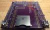
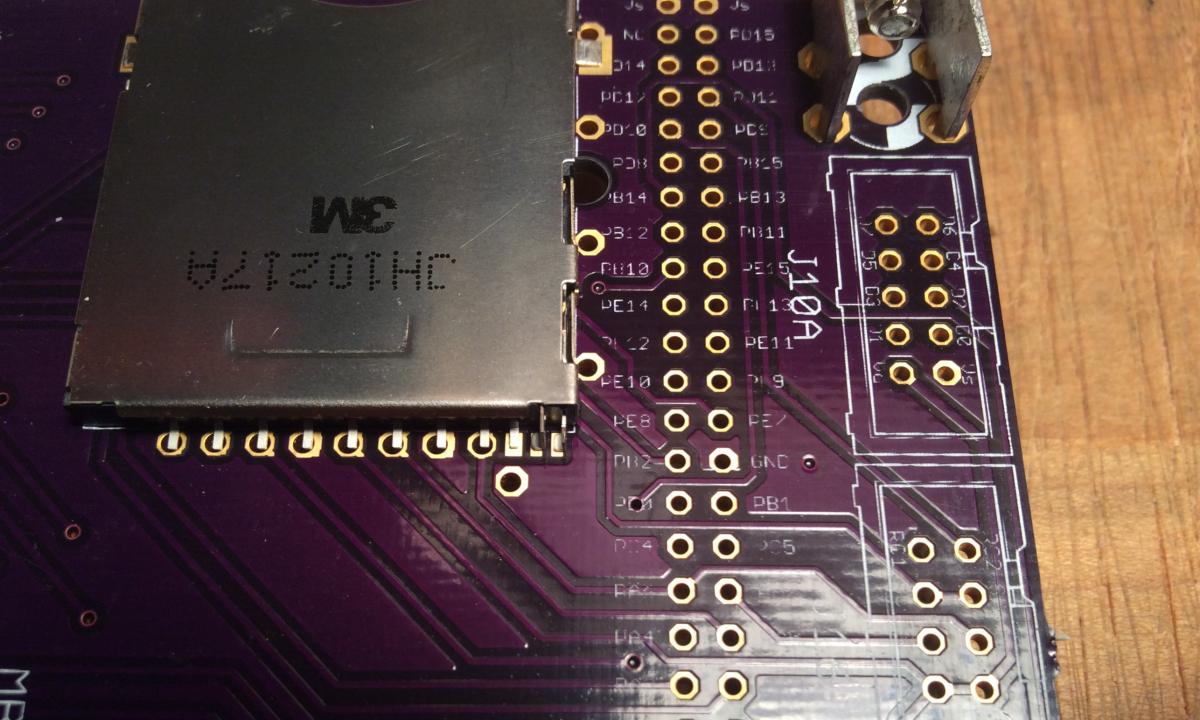
The SD card slot footprint on the board is designed to fit two different sockets. One is through hole but is impossible to get in small (less than 500) quantity. The second footprint I used on the layout is for the SD-RSMT-2-MQ since it had (and still has) the best small quantity availability out of all of the full size sockets on the market.
The SD-RSMT socket has some plastic guide pins that fit holes on the board so it stays in place during soldering. I quit worrying about getting the through hole socket when I soldered one of the SD-RSMT and found it trivially easy to do with a typical iron.
Best regards!
Tim
-
Hi mrzottel,
I have seen a few people over the years have similar issues with the 4685s. Statistically very rare but worth mentioning if it helps you get to goal....
Port latch-up (and a crashed app) due to a very noisy PSU during MIOS or app upload - was fixed with a few erase cycles on a programmer setup for HVP mode.
Weak VPP on a PICkit2 clone during programming - the write looked good but the chip had issues after MIOS was uploaded.
Bad flash on the PIC itself - extremely rare due to good testing/quality control at Microchip. I have seen a couple where the only thing changed was the PIC/exact same process and it worked as expected.
I have attached a known good/well tested hex file to load directly into the pickit 2 software. Use the G_0000 file and it will set the correct options and write both the bootloader and MIOS onto the PIC in one operation. If the symptoms change that will eliminate quite a few possible problems.
Let us know how it goes!
Best regards
Tim
-
Crossposted threads merged.
-
Adware infection on your browser.
http://www.symantec.com/security_response/writeup.jsp?docid=2014-111714-4334-99
http://community.norton.com/en/forums/rockettab-and-jollywallet
Best regards
Tim
-
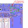
We definitely need to find a way to explain this better in the wiki - if anyone has any suggestions please post!
Short answer:
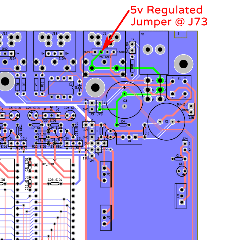
If your PSU generates regulated 5v, fit a jumper @ J73/connect pins 1 & 2 of J73 to each other.
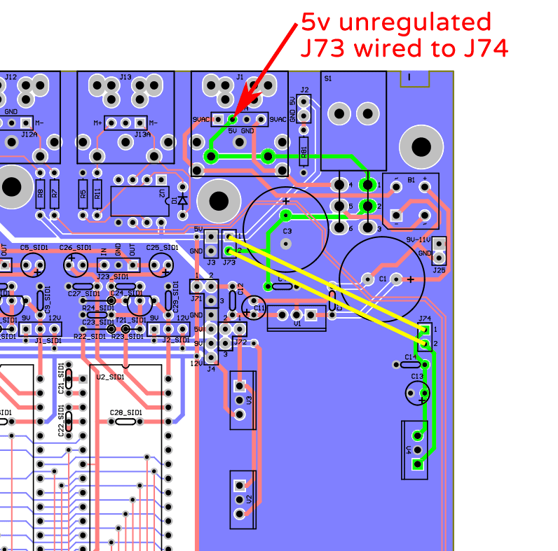
If your PSU generates unregulated 5v, wire J73:pin1 to J74:pin1 and wire J73:pin2 to J74:pin2. You will also need to fit C13, C14, and V4.
Long answer:
Regulated 5v input:
The 5v rail comes in @ J1, routes through the power switch, then a jumper at J73 ties the 5v rail to all of the 5v traces on the board.
5v path=green:
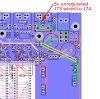
Unregulated 5v input:
The 5v rail comes in @ J1, routes through the power switch, then a wire from J73:pin2 to J74:pin2 takes it through V4 to give regulated 5v at J74:pin1. A wire from J74:pin1 to J73:pin1 connects that regulated output from V4 to all of the 5v traces on the board.
5v path=green/wires=yellow:
Best regards
Tim
-
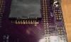
It is a Keystone 7700 (mouser #534-7700).
There are a few variants with different colored screws and metric/imperial thread pitch.
Best regards
Tim
-
Ahoy!
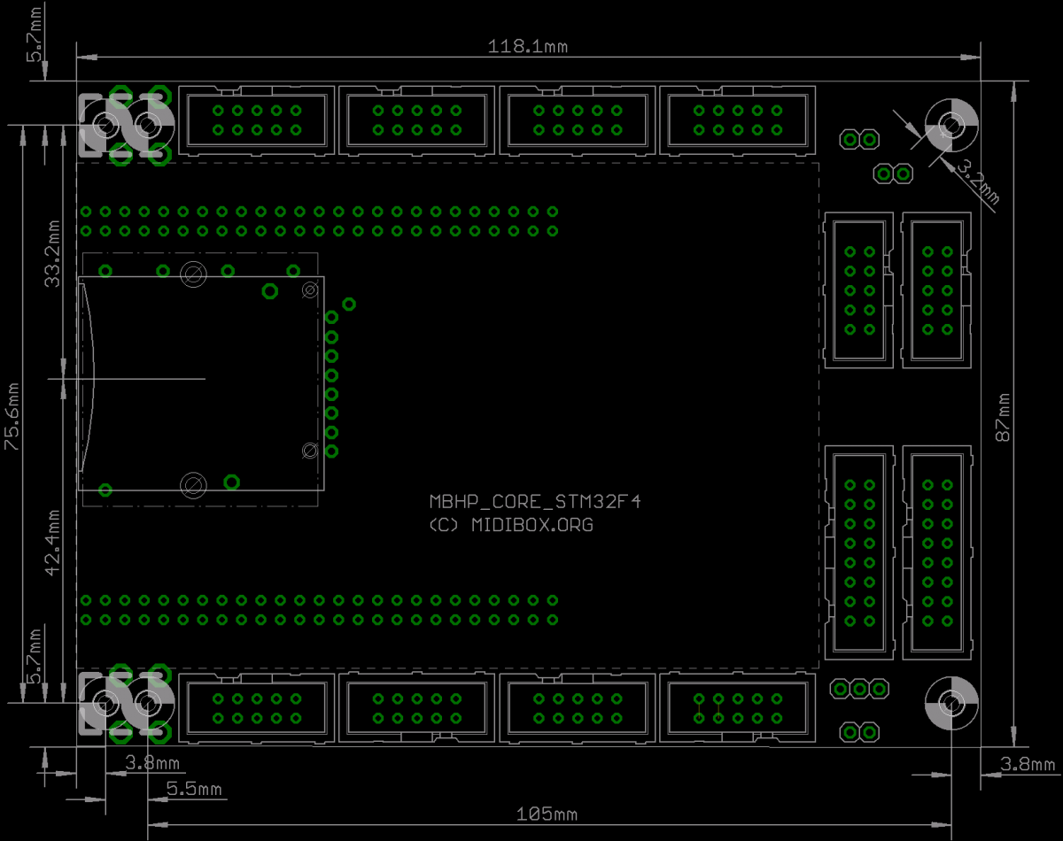
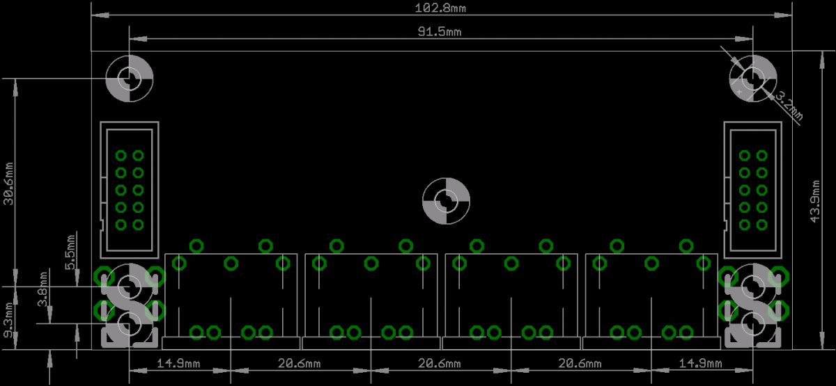
Please keep in mind that edge dimensions can vary by a few tenths of a mm depending on what size edge router bit they load in the tool rack that day.
Dimensional drawings:
PDF
Core STM32F4D_CORE_X9_7_dim.pdf
MIDI I/O MIDI_IO_X38_0_dim.pdf
PNG
Core
MIDI I/O
I also put the PNG files on the shop pages.
Best regards
Not-Mike :happy:
-
LOL I need to get a name tag made that says "not Mike"
No worries though this happens so often that it has become a source of amusement. :smile:
Best regards and happy new year to all!
Tim/SmashTV
-
Hi Novski,
There is some preliminary info (schematic & parts list) here: http://www.midibox-shop.com/mbhp_midi_IO.html
I will add more info very soon, trying to get eagle 3D to work with the current version of eagle took a lot of time but I finally have it working well enough to make my usual build pages for the new boards.
Best regards
Tim
-
Hi jjonas,
Does reading in the chip I sent change/show the configuration on the Elnec software?
Best regards
Tim
-
If you could send me the PICkit-ware binaries, I'd be very appreciative!
Fired @ your email.
Best regards
Tim
-
Hi guys!
I can't log in to edit the page at all :(Check this post for an explanation:
Unfortunately the spam bots are still aimed at the wiki so it will likely remain this way until we have a registration scheme they cant blow through on auto.
I had the wiki generate an account and send the info to your email, let me know if it gives you any issues.
I am still working through that list as quickly as parts availability and reply time from the guys on the list allow.... I usually ship a few each week. After the list is taken care of I will add the kit to the shop.
Back to the kitmill!
Best regards
Tim
-
Hi lis0r,
I would not dream of telling you there is no problem with the PIC chip(s), but I can tell you that I am very procedural about writing the chips. I write/run a pin scan on a test fixture, then move the chip to a customized core to send up the bootloader and MIOS. That rig lets me watch all of them boot/run/generate the proper sysex/drive an LCD.Definitely not trying to blameshift in any way by saying this but I thought some insight into the treatment they received here at the kitmill might help. :turned:
Core 3 works, however, cores 0-2 don't. I can query them, but an attempt to upload firmware bombs out 20-40% of the way through. They sporadically but rapidly spit out the following MIDI data:
f0 00 00 7e 40 00 0e 0b 01 f7
f0 00 00 7e 40 00 01 f7
I'm assuming they're rebooting? I've tried swapping core chips, and the good core works in whichever slot it's in. The voltages to the PICs seem steady.f0 00 00 7e 40 00 01 f7 is an upload request and the timing of the message is a clue to what is going on.
Bootloader only will generate this message over and over every 2 seconds until MIOS is loaded. (with the chips I ship this would only happen if the flash was corrupted/MIOS overwritten somehow)
Bootloader + MIOS will generate the message only once at startup.
Bootloader + MIOS + app will generate the message only once at startup.
So if the message is not repeating @ 2 second intervals or it is sending the message at random times not just once at boot it looks like a random reset issue.
The most common cause for random resets on a good supply with the SID app is the CAN bus termination - on the 6582 baseboard this is the 1N4148 "D1" diode under each PIC and "R80" located between PIC 1 and PIC 2. If these are missing/wrong or the diode(s) are backwards the SID app will reset at random even on a clean power supply.Some LCDs if wired for 8 bit mode instead of 4 bit will cause the same symptoms.
The upload problem(s) will likely change or go away once the reboot issue is sorted - failed uploads are a common symptom of a CAN bus termination issue.
App cloning works great for some but fails for others, and some have trouble with straight up SYSEX app uploading via MIOS Studio for the 2nd 3rd and 4th PICs. The quickest work around for this is usually to swap 0001-0003 into PIC 0000's socket one at a time to do the app upload, setting the SYSEX address in MIOS Studio to match the address for each chip (last two digits of the PIC ID string on the label).
I'm going to borrow a PICkit3 from work and see if I can reflash them back to "new", but I'm not hopeful. Have I just got bad PICs? :(If you go this direction I have some PICkit-ware binaries ready to load/burn without configuration issues I can send if you want them...... Setting the ID string for the bootloader programming ranges from easy to impossible depending on which PICkitware you are using.
Also, on one of the PICs, I'm pretty sure I accidentally wired 9v on U1_SID to pin 8 - is there any chance this hasn't damaged the PIC, or should I just order a new one now?Over the years I have seen PICs endure some amazing abuse in builds gone wrong and still work great..... I would say wait until the reboot and upload issues are solved then the test tone app will help determine if there is a bad pin/port.
Let us know how it goes!
Best regards
Tim -
Hi guys,
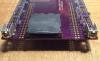
Connector fit test went very well - Waiting for the PCB fabrication to be completed.
To those waiting on an 'in process' order: I am pacing a hole in the floor waiting on some incoming parts. I have not forgot about you and I will ship ASAP.
Best regards
Tim
-
Grrrrr.......
Rev B does fit:
I will add a compatibility warning to the shop.
Best regards
Tim
-
Hi *,
I am a bit shocked at the whining about price - it is a huge value for what it does.
This is a big lvl up for those of us who need this feature set without an unreliable stack of kludges.
In my world pro gear costs pro money whether built or bought. Obviously people forget what the MIDIbox feature set would cost if it were not a labor of love.
Thank you Benoit for opening the door for us to play with and create the state of the art.
Best regards
Tim
-
Hi Benoit,
On behalf of some of the US MIDIboxers I would like to apologize in advance for your trip to the US. :happy:
Best regards
Tim -
Hi Csaba
This might be a simple wiring issue.....
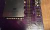
The two rows of pins @ J1 and J2 on the DIN boards from my shop are different, one row has the SO pin the other has the SI pin:


This can be an problem for guys who wire direct/without connectors or use single row connectors since it is easy to get on the wrong row.
I realize this seems like an error or bad design at first look - but it facilitates a mixed DIN/DOUT chain with simple 1:1 IDC connectors and ribbon cable saving hours of fiddly SIL connector crimping:
A bit more info in this thread:
Best regards
Tim


Where do the bridges go on the v4 core board
in MIDIbox SID
Posted
Take a look at http://ucapps.de/midibox_sid_manual_hw.html in the 'Minimal requirements' section.
And this schematic http://ucapps.de/midibox_sid/mbsid_v2_communication.pdf from the 'Resources' section.
There are more details about it posted long ago here on the forum.
Best regards
Tim