
Rigo
-
Posts
74 -
Joined
-
Last visited
Never
Content Type
Profiles
Forums
Blogs
Gallery
Posts posted by Rigo
-
-
Well I kindoff figure everything up with two cores. but is it possible to represent the playing bar position of 32 note clip with 32 leds in a linear array?
-
Thank you Ultra
-
To do this I use the drumrack then load lets say the same kick in the 16 slots that the drum rack has, then I draw the clip using a "diferent" Kick-note in a latter style, then i just expand the drum rack and assign midi notes to the 16 mute buttons each kick-note has. Its rather very simple, it can even be done with pots assign to volume.
-
Hi there every one,
It has been a long time with no post, work and loads of work and haven't had a chance to midibox, but again am back
Well, I don't really know where to post this but here it goes.
I finally found a way to interface live 7 with a hardware controller in a drum step sequencer manner ala Fruityloops to make drum loops. I have done it with a regular midi keyboard and it works but I ran out of keys. I really don't know where to start, this is the design.
I will have a 8rows x32columns button matrix (obviously each row represents an instrument[Kick,snare,etc] and each column a step), the first 4x32 sending midi in a channel different than the lower 4x32
I will need the first 128 step buttons to send the 128 notes (on/off) from C-1 to G9 on one channel
and the reamining 128 buttons to send the same notes on a different channel.
plus i will need some kind of led feed back to show the buttons status, and on the very top a row of 32 leds showing the position that is currently playing,
is this possible with midibox?
is it possible to keep sending notes in different channels to get enough buttons to complete a 12x32 matrix. or a 8x64?
I keep searching for this but all that comes out is the Midibox SEQ 3
Sincerely Rigo Renteria
-
am doing one of your Dinx4, and yes I changed all nine, I changed the registers and same thing.would it be wrong if, for now, I only use the 3 available inputs and leave D0 permanently grounded, would it cause some problems? am still going to check and recheck but I just want to know I have that option. Thank you so mucho for you help.
-
rah
Honestly .Do you realy think you can make a controller that can compete with m-audio, kenton, behringer, novation, akai etc, etc. Just try to make a decent box , just one box, with all the features of the comercial boxes, usb ports, divers, librarians, lcd screens, all manuals, professional looking panel, screen printing , memory banks, etc. I'll be surprised if you can make it under 100USD only for parts, not to mention labor costs.
-
Hi there again,
well I change the resistor pack for individual resistors, and the problem is still there, but I found something else, if I connect D0 of J6 to ground the notes on/off stop triggering constantly, although the only inputs that work are D4,D3, and D2, because the remaining either dont work at all like D1 or trigger 3 notes on/off at the same time like D5,D6,D7, could it be the 74HC165 then.?
-
Hi there, thank you for all your help
Well this is what I found;
I turn the unit without the 74HC165 chip and check the voltages they seem ok (5.3V) but after two minutes the voltage drops giving me the results I described earlier, am desoldering the resistor network and putting individual ones, in a few days I'll repost with the results
-
After a good inspection with a magnifying glass all tracks and soldering seem ok, I found something strange on Inputs (D7 and D6) of J6 with the multimeter every input reads 5V but D7 reads erratically from 2.4V to 4.4V and D6 reads constantly 2.8V. D7 is the one that is constantly triggering the note on/off, what should I do?
-
thanks Tim.
Well as far as the timing it is constant on-off-on-off but If I turn the unit off for a few minutes (20min) and turnit back on it doesn't start to do that (on-off-on-off) after a minute or two
but am checking for those shorts in the circuit, I'l keep you guys informed
-
I had the same problem and put all resistor networks correctly but now I have a problem with a button that keeps triggering constantly
3479587 1 -- 151 84 127 8 C 6 Note On
3479659 1 -- 151 84 0 8 C 6 Note Off
3479726 1 -- 151 84 127 8 C 6 Note On
3479760 1 -- 151 84 0 8 C 6 Note Off
3479863 1 -- 151 84 127 8 C 6 Note On
3479897 1 -- 151 84 0 8 C 6 Note Off
3479967 1 -- 151 84 127 8 C 6 Note On
3480001 1 -- 151 84 0 8 C 6 Note Off
3480036 1 -- 151 84 127 8 C 6 Note On
3480070 1 -- 151 84 0 8 C 6 Note Off
3480109 1 -- 151 84 127 8 C 6 Note On
3480142 1 -- 151 84 0 8 C 6 Note Off
3480176 1 -- 151 84 127 8 C 6 Note On
3480211 1 -- 151 84 0 8 C 6 Note Off
I had a realy hard time desoldering the resitor networks, so am thinking that i might have damaged one or two, I actualy disconnected the button but it just keep going, is this behavior due to something else?
-
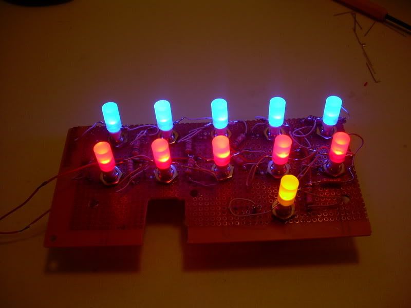
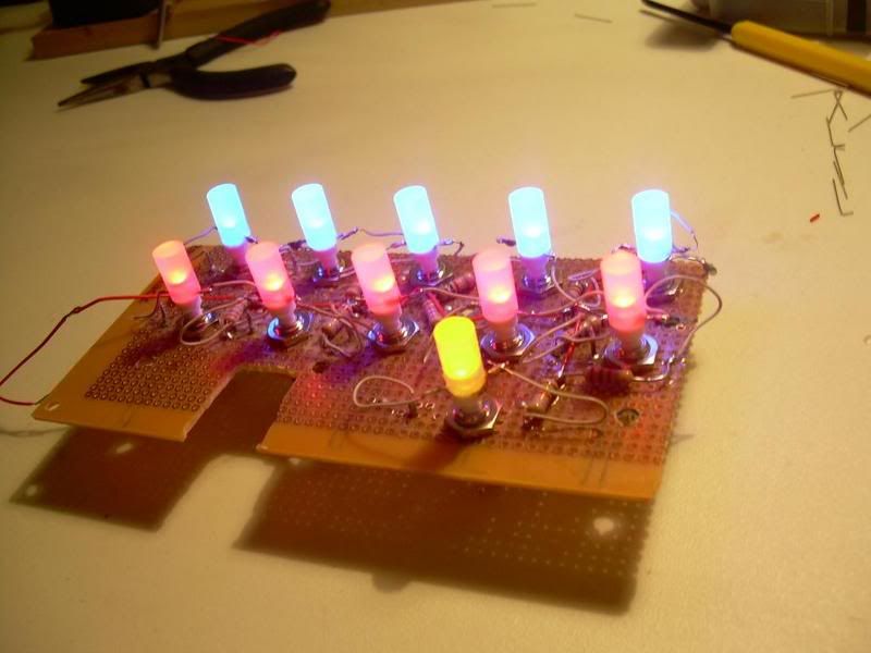
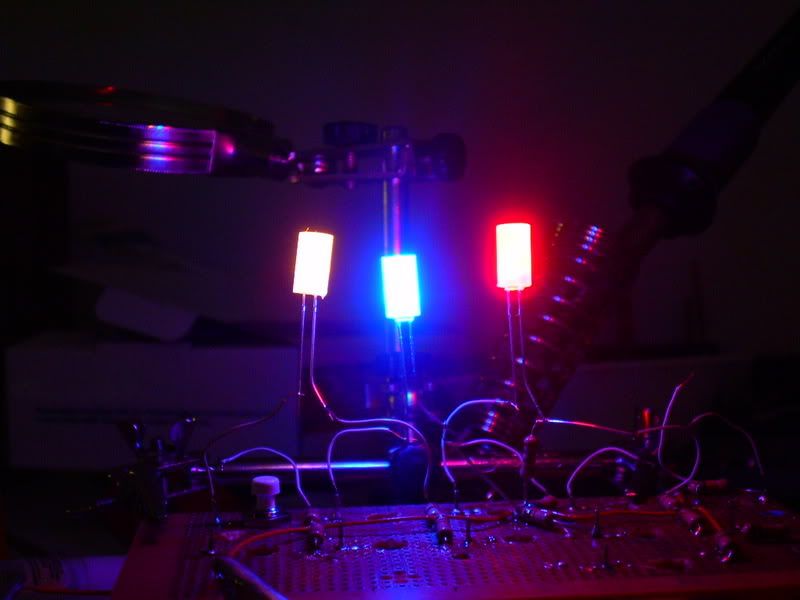
got some pics of the final result , looks rough but at the end it looks good, it is a shame that the camara does not capture an exact image of how they glow.
-
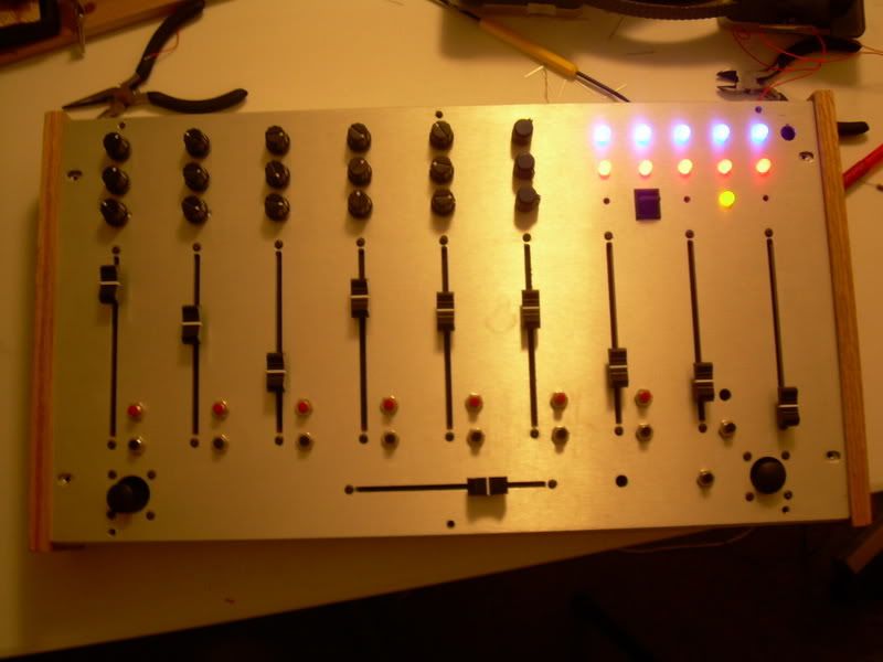
First of all thank you for all your coments,
Here are some pics of the backlit bottons, the board looks rough but at the end it looks good in the front pannel , I did a small change to the box too, I replaced the "giant" toggle switch (which was used to go up and down scenes) for a nice square rocker switch.
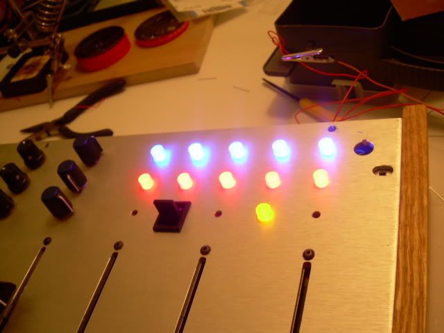
I still have 20 more to go......hehehe
again thank you all :)
-
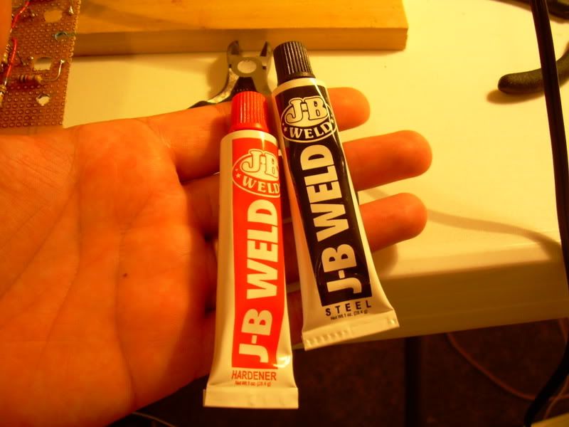
I google JB Weld and found this
this is an amazingly strong cold weld, I have seen with my own eyes how one of our mechanics "welded" an overheated cummins engine block, that was basicaly splited in half.
-
This is not the least expensive one but it makes out on the diffusion
I started working on an less technical and low cost alternative to do backlit buttons with common easy to obtain (cheap) switches.
This is what I came out with:
Aprox cost USD = $0.37 = $0.25 for the switch, $0.10 for the led, $0.02 for the rod, and a few drops of super glue.
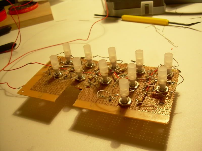
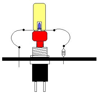
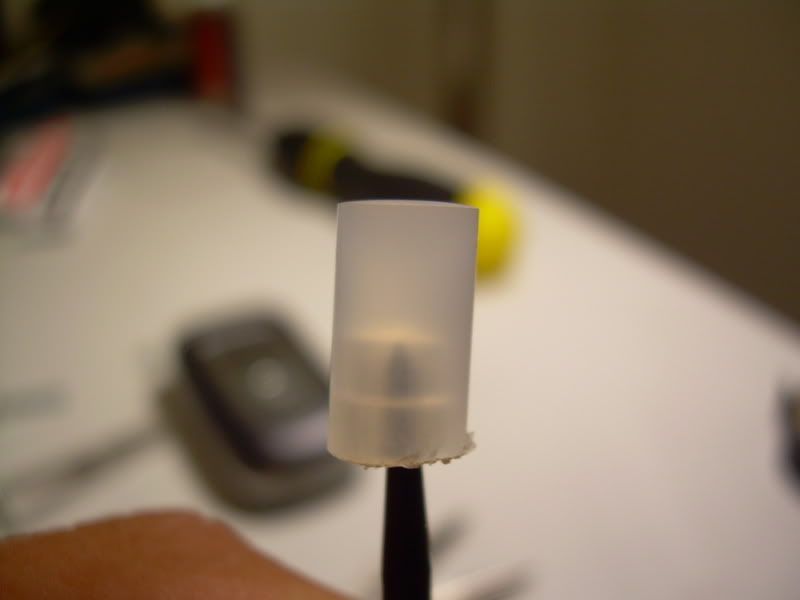
I started to work (with the suggested technique of Sasa Djuric described in here http://www.midibox.org/forum/index.php?topic=4322.msg28227#msg28227) with a piece of 1/4" diameter rod of cast acrylic (Plexiglas) I cut it to a 13 mm. piece then sand it with 200 sand paper, then with 400, then with a 600, to obtain a very satinized look, then bore with a very thin drill bit, going up in size till the led (T1 = +/- 3mm.) could go in. Then I cuted two notches for the legs to go out and then glued it to the top of those very cheap push down switches , the ones I have in my box, then used a 220 Ohm resistor with two little thin wires (out of a ribbon IDE connector) to connect the led, somewhat like the picture below:
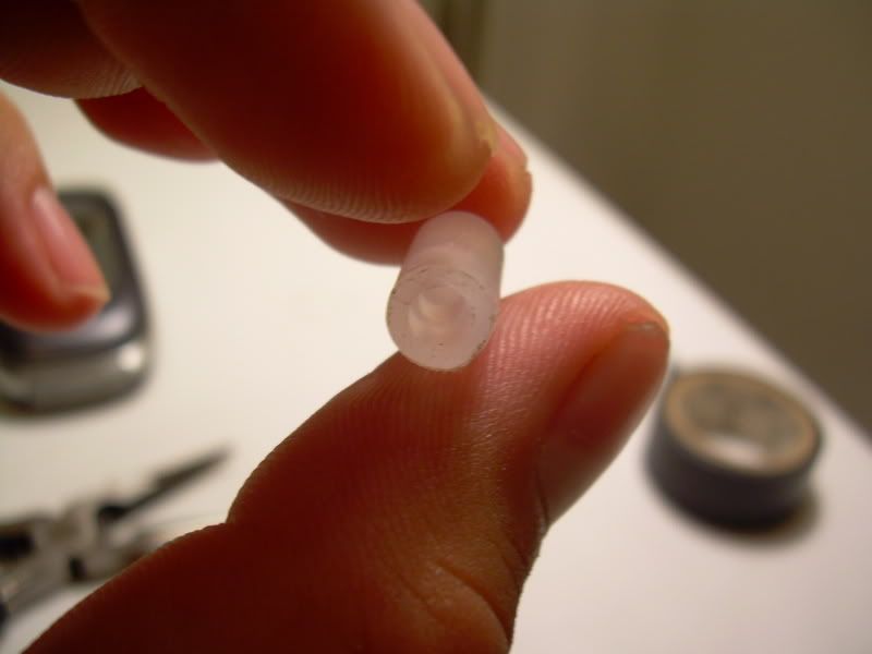
The problem is that Plexiglas is crystal clear inside so the diffusion actually takes place outside on the sanded surface, so everything looks good as long you don’t touch the button, I noticed that after a while the button gets translucent because of the oil in my fingers, it looses its "glow" (think about a sheet of paper saturated with cooking oil), so I decided to look for something else, something translucent rather than clear, and finally I came out with something good, I bought a 1/4" diam. polypropylene rod and started the same process I have pictures bellow of a final cap:
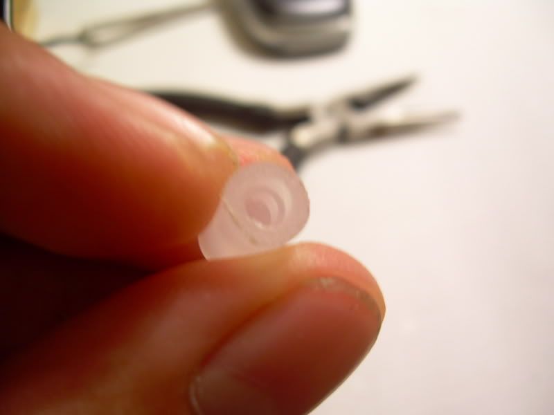
This material is great, it diffuses light inside out so nicely and I don't have the grease paper effect any more bellow I have some pictures with the led in, not the finished product but close:
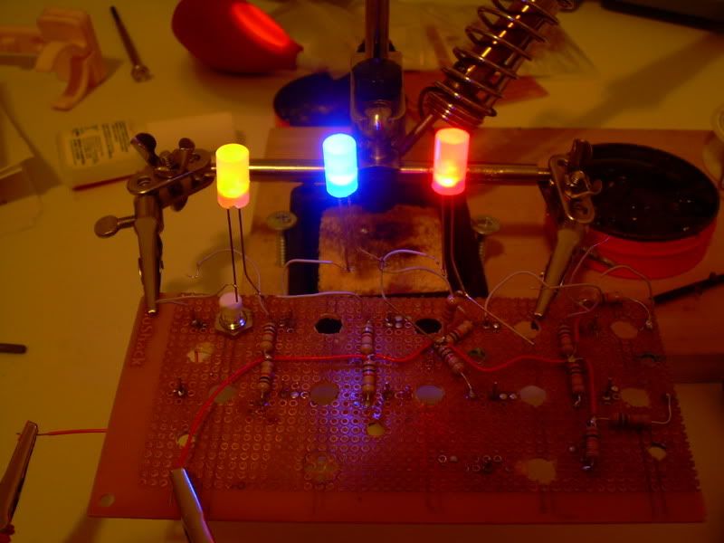
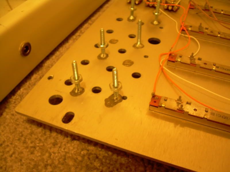
To mount them I bored a prototype board from radio shack like the one above and am going to place it under my front panel.
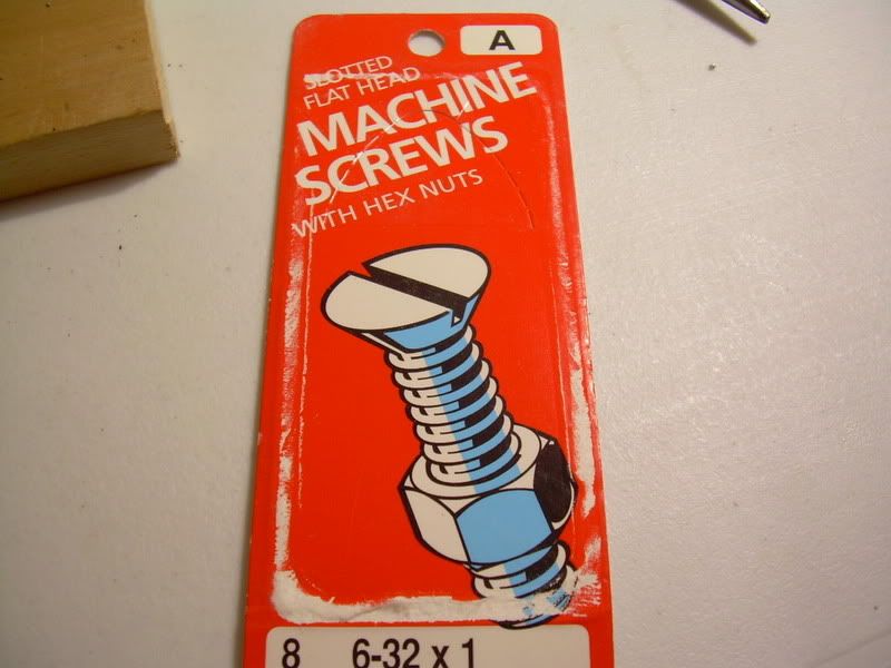
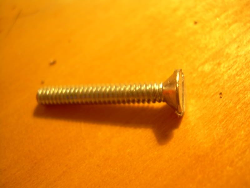
For this I used the famous JB weld to glue the screws to the panel, make sure you use screws that have a flat head:
That’s all for now I will post more pictures of the final product next time. For now just keep midiboxing......=)
thank you all for your support. specially my wife Kary.
-
No, I found it in my local hardware store, what me to send you some???
where are you located?, I bought it for $5 USD
-
Hi all, it has been a long time without a post, but I have new material........
I started working on an alternative (low cost) to do backlit buttons with common (cheap) switches.
This is what I came out with:
I started to work (with the suggested technique of Sasa Djuric described in here http://www.midibox.org/forum/index.php?topic=4322.msg28227#msg28227) with a piece of 1/4" diameter rod of cast acrylic (Plexiglas) I cut it to a 13 mm. piece then sand it with 200 sand paper, then with 400, then with a 600, to obtain a very satinized look, then bore with a very thin drill bit, going up in size till the led (T1 = +/- 3mm.) could go in. Then I cuted two notches for the legs to go out and then glued it to the top of those very cheap push down switches , the ones I have in my box, then used a 220 Ohm resistor with two little thin wires (out of a ribbon IDE connector) to connect the led, somewhat like the picture below:
The problem is that Plexiglas is crystal clear inside so the diffusion actually takes place outside on the sanded surface, so everything looks good as long you don’t touch the button, I noticed that after a while the button gets translucent because of the oil in my fingers, it looses its "glow" (think about a sheet of paper saturated with cooking oil), so I decided to look for something else, something translucent rather than clear, and finally I came out with something good, I bought a 1/4" diam. polypropylene rod and started the same process I have pictures bellow of a final cap:
This material is great, it diffuses light inside out so nicely and I don't have the grease paper effect any more bellow I have some pictures with the led in, not the finished product but close:
To mount them I bored a prototype board from radio shack like the one above and am going to place it under my front panel.
For this I used the famous JB weld to glue the screws to the panel, make sure you use screws that have a flat head:
That’s all for now I will post more pictures of the final product next time. For now just keep midiboxing......=)
thank you all for your support. specially my wife Kary.
-
thank you guys , i dont have a multimeter right now, could you tell me what values should I look for if am planing to put 31 LEDS all to be on at the same time I was thinking of getting voltage directly out of the wall adapter before it gets to the core, ?
any suggestions as far as led -resistor conbinations for 31 leds?
-
ok the photos are up again,
-
Am I doing this right?:
I bought several LEDS at radioshack and I am using a 220 ohms resistor, for testing,
am doing backlit bottons (about 20 T1 Leds), could I use the same resistor value for each, also could I use the power out of the core??? for it.
-
creo que no existe diferencia entre mac y pc porque todo se controla via MIDI y pues el midi no tiene que ver con mac o pc.
-
Veniste a dar justo al lugar indicado, el maven, aunque sasha y/o sus compañeros no lo admitan esta justamente basado en la plataforma MBHP (Midi Box Hardware Platform) claro con algunas modificaciones, y creeme lograr armar uno es mucho mas facil de lo que piensas, bueno esto ya se a discutido mucho (sobre sasha, el maven y MBHP) en fin:
Ok Primero tienes que decidir que es lo que en verdad quieres
segundo (ejemplos):
el corazon de todo proyecto Midibox es el Modulo llamado "Core" algo asi como el modulo central
para conectar un maximo de 32 pots (potenciometros regulares o deslisables) utilizas el modulo AIN (analog input)
asi pues
1 CORE + 1 AIN = A un controlador con 32 pots (claro sin pantalla lcd, o midi thru pero funcional y estable)
1 CORE + 2 AIN = un controlador como el de arriba pero con 64 pots
Asi si sigues añadiendo modulos mas funciones tendras como pantalla lcd, indicadores de actividad , midi thru, puerto para memorias de los preset asignados a cada pot, con los modulos din puedes usar ecoders en vez de pots, en fin las posibilidades son muchas, pero para comenzar, yo diria algo asi como lo que hice yo, un midi box con 32 pots, sin leds, sin lcd, sin midi thru, solo para controlar live y nada mas.
ya que tengas decidido que vas a constuir y con que:
compras o armas lo modulos tu mismo:
yo los compre de la tienda de smashTV
una ves que tienes los modulos armados programas el core via midi
conectas el Modulo AIN y a controlar live????
ve a midibox.org luego click en uCApps. de y hai veras mas informacion
-
>:( something happened with the photo links ??? ???, I have to check what happened, meanwhile I am currently working in a very very cheap alternative for backlit bottons for my box based on the method led inside-plexyglass-glued to botton same as a few guys have done it. I will post some pics for the work in progress.
-
forgot to tell you looks like the motion dive tokyo controller theme.
again very very nice
Is it possible - LED Array to represent position?
in MIDIbox HUIs
Posted
Is it possible to have a linear array of 32 LEDs and receive Midi time code from Ableton LIVE (playing a 32 note clip) to represent the position (note) LIVE is currently playing, so if you have a loop of 32 notes in LIVE the LEDs light in the same loop manner from start to finish and back again and again, is this possible with MIDI Box LC? I search and seach and can't find anything.