

John_W._Couvillon
-
Posts
350 -
Joined
-
Last visited
Content Type
Profiles
Forums
Blogs
Gallery
Posts posted by John_W._Couvillon
-
-
Hi guys
I will have them in stock soon, just waiting on the fabrication run to be finished.
Best regards
Tim
Hi Tim,
hooray!! for smashtv!
Will you have complete kits, everything included?
I am going to hold up my project and wait for you.
Do you have any idea at all when we can start placing orders?
johnc
-
TK,
I responded to the bulk order post this morning, but I suspect that I was too late. Is that the case?
Do you plan to do another batch?
johnc
-
Btw.: I've worked on MIDIO128 V3 in the last days.
It runs on a MBHP_CORE_LPC17 module and will provide such nice features like:
- storing/restoring presets on SD Card
- integrated MIDI file player (files played from SD Card)
- support for USB MIDI
- support for up to 3 MIDI IN/OUT ports
- support for OSC over Ethernet
- optional user interface which can be directly connected to the core (no additional shift registers required): http://www.ucapps.de/mbhp/mbhp_scs_proto2.jpg
- device can also be configured from the MIOS Terminal in MIOS Studio
- preset files can be edited as a spreadsheet in Excel (or OpenOffice)
Adding a 32x32 matrix driver would be a simple task for me, so if you are interested I could add this option
Best Regards, Thorsten.
TK,
Thanks for the response.
I think that it would be great to incorporate the 32x32 matrix capability into the ver.3 of midio128. I am not current with the MBHP_core_LPC17, other then it is a much more powerful core, with much more of a future then the old 18F452 core that I am using.
Will there be a ver.3 that will run with the older cores, such that I should hold up for a while on my project, and forget about adapting the QBAS 32x32 app?
If not, then I am too far along to start over with the new core. Jim henry and elepharo had success with getting the 32x32 app working (miditzer forum), so my plan is to continue along the same path they followed.
However,in support of those looking to apply the diode matrix to midifying keyboards, I encourage you to continue with whatever your plan for Ver.3 of midio128 as regards the 32x32 matrix.
I did repair the links to the pictures of my project, so have a look.
Thanks again,
Johnc
-
Back to the matrix subject.
For other midibox users:
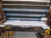
Following the thread mentioned by jim henry in his post above, The pictures below show my progress in setting up the hardware for a 32x32 matrix to encode three keyboards plus pedal.
The DINX4 and core(18f452) are new. The DOUTX4 is one previously as a pipe magnet driver and had the ULN2803 chips. Those have been removed and jumper switches installed to bridge from chip to connectors. The PCB at the bottom of the assembly routes the DOUT outputs to connectors. Since the output connections were soldered to the pins, I didn't want to try to de-solder fearing heat damage.
Voltage checks have been completed, as well as continuity check for bad solder joints, so all is ready to install the ic's and fire it up.
The plan is to use the QBAS 32x32 app, or some modification of same developed by Jim Henry (thread on miditzer forum).
The assembly will fit under the keyboard along with the core.
Johnc
-
Anyone,
I am looking for a 0 ohm shorting bridge to use on a DOUT card in place of the ULN2803 driver chip.
Would appreciate help finding same if anyone knows a source.
Thanks,
Johnc
-
TK, anybody
The output pin on DOUT is connected through a diode and key contact to the input pin on the
DIN. What value pull up resistor should be on the DIN PIN?
Is a pull up resistor needed on the Dout output pin?
Will the voltage drop to ground on the DOUT pin be lower if a ULN2803 driver chip is used at 5vdc inbetween the shift register and the output pin similar to the setup for driving magnets?
Thanks,
johnc
-
I have 3 18F452 pics that are over 5 years old running mios and midio128. Can I over write the older versions with current, or is there an update to being them current.
Thanks,
Johnc
-
Hard to imagine. Thorsten measured the switch matrix at about 80 microseconds for 64 notes input. Partswise you should be able to do a switchmatrix on the Trio with a core, 3 input registers and two output registers. Â The PCBs are more expensive than the parts on the shift registers. Â The necessary diodes are about $4 in the US. Â Of course you can't value your time at anything or the costs go through the roof. ;D But I look forward to hearing what you are thinking!
Jim Henry,
Is the download reference you included earlier, before TK mad his adjustments, current with all suggestions from TK, If not, please arttach a new reference.
I have a three manual keyboard stack with keyboards configured almost exactly like the units that TK included in an earlier post. Each has 8 points for col's/8 points for rows. Can the matrix be expanded to an 8 x 32 so as to use one core, rather then 3 with the 8x8 matrix? If this has been done, could out point me to the thread. The switch matrix thread has spread out over so many posts, that it is difficult to find the most recent data.
Thanks,
Johnc
-
Jmayes,
I read over the BLM threads, etc. and really don't understand what I am reading. I have no interest in led, or the switch box, just some specifics about using an 8x8x1 on each of my keyboards, or an 8x8x4 on all four. each of the keyboards has a full length pc board with diodes in place and 16 wires hanging out. Each keyboard is already setup in a matrix. the 16 wires are 8 on rows, 8 on columns. Probably 4 cores with DIN/DOUT, each running the 8x8 example from tk would work, but 1 core with DIN/DOUTs would also work. TK had some pictures posted with a similarly constructed KB and a small PC board for Dout/Din. That would work for me also, but thread seems to have run out.I will be happy to set up a working model of an 8x8x4 if code for same is available.
johnc
-
Wow, great!
Btw, you are one month ahead of time (see the date stamp in your schematic :whistle: ).
Ok Mr.Ilmenator! Sorry about that.
johnc
-
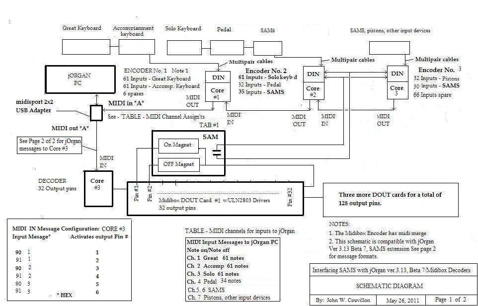
Forum,
If you are a user of jOrgan virtual organ software as the front end relay for midification of a physical console, using MIDIBOX cores,DINS,DOUTS as encoders and decoders, you can now interface jOrgan (ver. 3.13, beta 7)with SAMS using midio128, core, 4 DOUTS with ULN drivers and the new SAMS Extension feature in jOrgan. The attached partial schematic shows the key hardware and interconnections.
More information is available on www.jorgan.sf.net, and the jOrgan forum.
johnc
-
Thanks TK, you made my day!
Johnc
-
TK,
Is it possible to use duplicate midi note numbers in the outputs if the channel numbers are different?
Pin# Byte 1 byte 2
1 = 90 1
2 = 91 1
johnc
-
Jmayes,
Don't quite understand the following where you said:
"The hookup is to scan the whole keyboard at once with 2 DINx4 boards rigged with pulldown resistors, then the bussbars are driven with a positive pulse."
So it takes 2 DIN boards (64 inputs). Do the positive pulses come from DOUTS? How many?
So it is an 8x32 matrix?
My keyboards have pc boards attached with diodes, all pre wired in an 8x8 matrix - 16 wires each board 8 in and 8 out. How could thie interface with the core etc. See attached pic.
Johnc
Sorry, can't get the pic to upload
-
Jmayes,
Don't quite understand the following where you said:
"The hookup is to scan the whole keyboard at once with 2 DINx4 boards rigged with pulldown resistors, then the bussbars are driven with a positive pulse."
So it takes 2 DIN boards (64 inputs). Do the positive pulses come from DOUTS? How many?
So it is an 8x32 matrix?
My keyboards have pc boards attached with diodes, all pre wired in an 8x8 matrix - 16 wires each board 8 in and 8 out. How could thie interface with the core etc. See attached pic.
Johnc
-
No, Sorry it's on the example application in C so no ini file, just straight mapping key1=0, key2=1, etc. An offset would be easy to add though. Each keyboard outputs on a different midi channel. At this point it can scan 4 keyboards (3 keyboards + Pedals) in 8ms which might leave for to much latency for some but I could let you try it if you like. Going to port it to the mios32 platform from here, I have to get it up to 10us per keyboard in order to match the scanning of my organ and make it work in tandem.
Did you see my SAMS project in the other thread? I am wiring it in now and it is working great!
Jmayes
Jmayes,
yes I downloaded it a few minutes ago. I have been able to get the SAMS console working in jOrgan ver.12.2, but will take a look at your solution as well.
As for the scan matrix, I have a Savile 3 manual keyboard that is partially setup for matrixes, including diodes. I will need to cover the 3 manuals as well as pedal, pistons, stops, swell.
Can the matrix driver be run under mios 8? I have 4 older cores with the 18F pic available running mios8. 8ms seems to be slow. Correct me if i am wrong, but TK's 8x8 is supposed to run in 1ms.
Johnc
-
Hi, I think I have good news. I have achieved a 64x4 matrix scan using the dio128, it also gives you the normal 128 outputs and 8 analog in's. I am using the Acont pins to mux the keyboard buss's and 2 dinx4 modules wired across the keys. Each matrix level outputs on the next channel up. I plan on publishing the project in the next few days.
Hopefully that will help,
Jmayes
Jmayes,
Great!
I'm anxions to see what you have worked out.
I presume that since it is midio 128, you still have use of the .ini file?
johnc
-
Forum,
Over the last several years, several members have embarked on projects to develop working matrices of different configurations, namely; TK, QBAS, jim Henry, Robin Fawell, and others.
Would those listed plus anybody else please reply to this post with updates to include, code updates, links to webpages with results of tests or working setups, experiences, etc.
TK - has anyone tested your last scan 8x8 matrix example as you requested some time ago.
Robin - per out private emails, you have made progress many would appreciate.
Personally, I am sitting on a three manual keyboard stack built by Savile organs that formally operated with a very early matrix design. each keyboard includes diodes and is partially matrixed. i know that midio 128 will do the job, but is that the most efficient way to go?
Thanks to all!
Johnc
-
Yes, it not only can be done, but I built a 5 rank pipe instrument using midibox devices for all encoding and decoding functions. jim henry is absolutely correct about jOrgan, it is a super relay replacement and can duplicate all functions normally found on a pipe organ, including combination action. Read back posts on the midification topic, especially back in 2005.
Good luck
Johnc
-
Jim Henry,
I know that your post is old, but what ever happened to your work on the matrix project?
Johnc
-
Robin,
see photo attached
Johnc
-
Robin,
What is the current status of your 16x16 matrix project? I have not been attentive to updates of the posts on this subject, but still have a 3 manual stack to midify, but am having no luck. The photo below will illustrate what my keyboards look like. They were originally in a matrix, but that part o of the original instrument was not liberated. Actually, each of the keyboards is set built for use in a matrix, as you can see from the blowup. As a last resort, I can use TK's 8x8 arrangement with one core per keyboard, but one 16 x 16 would do the trick with one.
Would appreciate any help you might be inclined to offer.
Jim Henry - If you read this post, any input you may have, built on your collaboration with TK on the same subject, would also be great!
Thanks
Johnc
attachments - to follow - files to big
-
ok Trevor
Yes some stupidty showing, the Java app is for jOrgan.
Can this be added on top of jOrgan, or does it go in one of the jorgan folders?
Help me out here - how do i get from the printed text you posted to an app to load?
Thanks,
Johnc
Trevor,
Since your development is not mios based, what hardware is required to run the Java, a core running mios128, plus DINs and DOUTS? Can this additional core be daisy chained with encoders for keyboards, pedal, pistons, etc.
This looks good!
Johnc
-
Trevor,
Since your development is not mios based, what hardware is required to run the Java, a core running mios128, plus DINs and DOUTS? Can this additional core be daisy chained with encoders for keyboards, pedal, pistons, etc.
This looks good!
Johnc
If anyone is interested, I threw together a little java app today that will handle SAMs from jOrgan. It's not MIOS-based of course, but it should do the trick until a better solution is found. It's set up to handle 64 SAMs on channel 10 (0-based); 0-63 are the ON magnets, and 64-127 are the off magnets.
Here's an example:
Stop #1
Activated: 155 0 127
Deactivated: 155 0 0
Stop #2
Activated 155 1 127
Deactivated 155 1 0
Stop #3
etc....
When Stop #1 is Activated, the app receives 155 0 127 (note 0 on, channel 10). The app then outputs 155 0 127, waits 333ms, then outputs 155 0 0.
When Stop #1 is Deactivated, the app receives 155 0 0 (note 0 off, channel 10). The app then outputs 155 63 127, waits 333ms, then outputs 155 63 0.
If anyone ends up building this from source, you'll have to change the two device name strings to the names of your input and output devices. Also you can change the delay time to fit your SAMs. I'm using a slightly longer time, because I'm using the original electro-pneumatic combination action. Eventually I'll make a GUI for this.
SAMs.java
import javax.sound.midi.Transmitter; import javax.sound.midi.Receiver; import javax.sound.midi.MidiUnavailableException; import javax.sound.midi.MidiDevice; import javax.sound.midi.MidiSystem; public class SAMs { private static boolean DEBUG = false; public static void main(String[] args) { /* The device name to listen to.*/ String strDeviceName = null; DEBUG = true; strDeviceName = "In From MIDI Yoke: 2"; if (DEBUG) { /*out("MidiInDump.main(): device name: " + strDeviceName);*/ } if (strDeviceName == null) { //out("device name not specified!"); System.exit(0); } MidiDevice.Info info = getMidiDeviceInfo(strDeviceName); if (info == null) { //out("no device info found for name " + strDeviceName); System.exit(1); } MidiDevice inputDevice = null; try { inputDevice = MidiSystem.getMidiDevice(info); inputDevice.open(); } catch (MidiUnavailableException e) { if (DEBUG) { } } if (inputDevice == null) { //out("wasn't able to retrieve MidiDevice"); System.exit(1); } Receiver r = new InReceiver(); try { Transmitter t = inputDevice.getTransmitter(); t.setReceiver(r); } catch (MidiUnavailableException e) { if (DEBUG) { out(e); } } /* Now, we're entering an endless loop. Otherwise, the program would exit and we won't have a chance to see any results. */ while (true) { try { Thread.sleep(1000); } catch (InterruptedException e) { if (DEBUG) { out(e); } } } } /* * This method tries to return a MidiDevice.Info whose name * matches the passed name. If no matching MidiDevice.Info is * found, null is returned. */ private static MidiDevice.Info getMidiDeviceInfo(String strDeviceName) { MidiDevice.Info[] aInfos = MidiSystem.getMidiDeviceInfo(); for (int i = 0; i < aInfos.length; i++) { if (aInfos[i].getName().equals(strDeviceName)) { return aInfos[i]; } } return null; } }InReceiver.javaimport javax.sound.midi.MidiDevice; import javax.sound.midi.MidiSystem; import javax.sound.midi.InvalidMidiDataException; import javax.sound.midi.MidiUnavailableException; import javax.sound.midi.MidiMessage; import javax.sound.midi.ShortMessage; import javax.sound.midi.Receiver; public class InReceiver implements Receiver { static Receiver rout; public InReceiver() { try { MidiDevice outputDevice = null; String outputDev = "Out To MIDI Yoke: 1"; MidiDevice.Info info = getMidiDeviceInfo(outputDev); outputDevice = MidiSystem.getMidiDevice(info); outputDevice.open(); rout = outputDevice.getReceiver(); } catch (MidiUnavailableException e) { System.out.println(e); } } public void close() { } private static MidiDevice.Info getMidiDeviceInfo(String strDeviceName) { MidiDevice.Info[] aInfos = MidiSystem.getMidiDeviceInfo(); for (int i = 0; i < aInfos.length; i++) { if (aInfos[i].getName().equals(strDeviceName)) { return aInfos[i]; } } return null; } public void send(MidiMessage message, long lTimeStamp) { int evnt0 = ((ShortMessage) message).getStatus(); int evnt1 = ((ShortMessage) message).getData1(); int evnt2 = ((ShortMessage) message).getData2(); if (message instanceof ShortMessage) { if(evnt0 == 155) new SetSAM(evnt1,evnt2,rout).start(); } } } class SetSAM extends Thread { int i; int pinnum; Receiver rec; SetSAM(int evnt1, int evnt2, Receiver r) { rec = r; if(evnt2>0) { pinnum=evnt1; } if(evnt2==0) { pinnum=evnt1+64; } } public void run() { ShortMessage on = new ShortMessage(); ShortMessage off = new ShortMessage(); try { //turn magnet on on.setMessage(155,pinnum,127); rec.send(on, -1); } catch (InvalidMidiDataException e1) { e1.printStackTrace(); } try { sleep(333); } catch (InterruptedException e) { e.printStackTrace(); } try { //turn magnet off off.setMessage(155,pinnum,0); rec.send(off, -1); } catch (InvalidMidiDataException e1) { e1.printStackTrace(); } } }


Diode Matrix Input
in MIDIfication
Posted
TK,
For the Record, with Jim Henry's help, I have a 32 x 32 matrix working. The code is the QBAS code with modifications Jim worked out over time.
I have it working a three manual keyboard soon to include the pedal, stops, pistons, etc. I concocted a setup of one din4x and one dout4x and it sits up under the keyboard. The core is a new (8bit)with the new mios and bootloader. It has only one problem, about .5sec latency on all three keyboards. Not excessive, but its there.
Strangely, in comparing your example code to the modified QBAS, I don't see anything referring to debouce timer in the QBAS, which is confusing, as there is no bounce at all. I looked in the sm_fast.inc code but didn't find it. Could it be someplace else?
Contrary to my previous email, I have in my possession the new LPC-17 processor, and am hoping that SMASHTV comes up with the pcb kits soon. It should be very easy to change over to the new setup by unplugging the din/douts from the old and into the new.
Johnc