
Marxon
-
Posts
474 -
Joined
-
Last visited
-
Days Won
4
Content Type
Profiles
Forums
Blogs
Gallery
Posts posted by Marxon
-
-
Hi!
Such high values are desturbing.
I would first measure the USB port voltage when nothing is connected.
Marxon
-
Hi!
Solder BS1 and BS2 to GND.
The missing BS0 is mostly internal connected to GND.
Best regards
Marxon
-
Hi everybody!
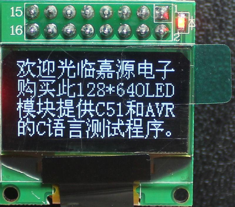
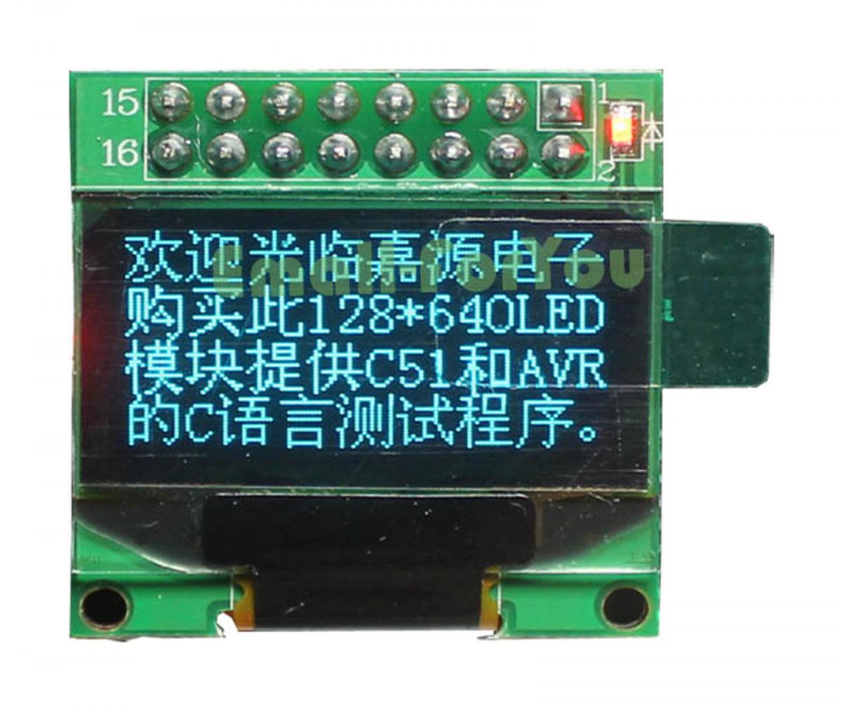
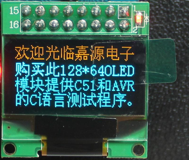
I want to start a bulk order of SSD1306 OLED displaysLINK
Here are the technical details:
Controller:SSD1306
Pixels: 128x64
Panel Size: 26.70mm x 19.26mm x 1.85mm
Active Area: 21.74mm x 11.2mm
Module size:28.mm x 27.1mm
Dot Size: 0.15mm x 0.15mm
Drive Duty: 1/64 Duty
Support interface: 6800/8080, parallel interface, IIC, 4 SPI, 3 SPI
Voltage:3.3VThey are available in 3 different colors.
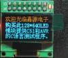
White
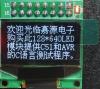
Blue
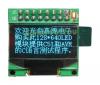
Yellow-Blue
The pinout is somewhat different than in Thorsten's schematic but
i have already tested the displays and they are working without problems
on my LPC1769 and STM32F4 cores.
------------------------------------------------------------------------------
The Dealer offers following prices:
if ordered 1pcs = 5,80€ / 7,78$ per pcs.
if ordered >= 50pcs = 5,35€ / 7,18$ per pcs.
if ordered >= 100pcs = 4,66€ / 6,25$ per pcs.
if ordered >= 200pcs = 4,25€ / 5,70$ per pcs.
Everyone pays the same price per pcs.
regardless how many Displays he ordered
---------------------------------------------------------------------
Shipping:
Germany (unversichert) = 1,45€
Germany (versichert) = 5,40€
International (uninsured) = 3,45€ / 4,90$
international (insured) = 7,10€ / 10,06$
(Shipping costs can be reduced
if the pin header is cut off
so the Display takes less space)
-----------------------------------------------------------------------------------
Orders can be submitted until 07 September 2014.
Shipping to me in germany will take 4-6 weeks.
Afterwards it will take another 3-30 days (depending on distance)
until all displays reaches their owners.
-------------------------------------------------------------------------------------
Payments can be done via Paypal.
(payments from germany can be done by bank transfer)
Paypal fees = 1,9% + 0,35€ / 0,47$
-----------------------------------------------------------------------------------------
ORDER LIST
Simply reply to this topic and write down your name, quantities, display color and shipping destinaion.
Use your full and correct forum name, so I can reach you via PM.
Everybody gets an order confirmation and
an invoice after the order deadline
By putting your name on the list you agree to the terms and conditions described here:
www.midibox.org/dokuwiki/nils_bulk_terms
Best regards
Marxon
-
My settings:
- all BS bridges are set to 0
- voltage jumper is set to 3V
- lcd_type is set to 0x84
- led_num_x and lcd_num_y are set to 1
- lcd_heigh and lcd_width are set to 128 respectively 64At the moment i am using just the bootloader app.
EDIT:
I've just noticed the following:
After changing the number of displays with the bootloader app,
then MIOS studio does initialize them and reports which displays failed to initialize.
If i use character displays and connect less character displays than i have set,MIOS studio reports the missing ones correctly.
But when i use SSD1306 displays, then MIOS studio does not recognize missing onesregardless how much displays have been connected.
Is this a normal behavior?
-
Hi again and sorry for my late reply!
I tried to connect the display to Port J10B of my STM32F4 core
but it still does not work. :( The led goes on but the display shows nothing.
Is there any minimum configuration (like connecting Vdd, Vss and Vo of a standard display)
to test if the display is generally working?
Best regards
Marxon
-
STM32F4
I only measure 2,9V on my 3,3V line...
could this be a reason?
-
Hi novski!
Sorry my schematic was not the best choice.
It´s more to show the different pinout of the JY-MCU display
compared to the one from TK HERE.
Of course i dont use the same CS line for both displays and no second resistor/ capacitor :smile:
Nevertheless i have connected D7 instead of D0 to the display CS pin, like you said but it still does not work.
-
Hi all!
I have exactly the same display but unfortunately i cant get it work on my STM32f4 core.
The screen stays black only the led gets on.
My core module should be OK because character displays are working properly.
Settings:
- all BS bridges are set to 0
- voltage jumper is set to 3V
- lcd_type is set to 0x84
- led_num_x and lcd_num_y are set to 1
- lcd_heigh and lcd_width are set to 128 respectively 64
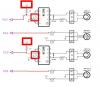
Thats my display wiring:I soldered 1k resistor and the 10uF capaciator directly on the core board andadded a connection from the core to the display RES pin.What could be problem?Best regardsMarxon
-
Hi TK!
MIDIbox NG supports only a single display type.Oh OK, i did not know that. But that´s no big problem.
To use a second display was anyway an optional idea.
If really needed then i still can use a second core,
But maybe it would be helpfull to mention this "circumstance" in the LCD chapter from the NG manual.
Have a nice weekend!
Best regards
Marxon
-
Sorry i made a mistake:
Because i like to use four SSD1306 and two 16x4 displays connected to J15A respectively J15BCorrect are four SSD1306 and two 16x2 Displays
-
Hi novski!
Thanks for your info and your board looks nice too!
Do I see correctly that you moved the 595 from the core to the lcd board?
Are short lines from the chip to the displays better? Or is it because an easier chaining of your display boards?
Another NG question:
Is it possible to use different LCD types at the same time?
Because i like to use four SSD1306 and two 16x4 displays connected to J15A respectively J15B
but i guess it´s not possible because there are only two "enable" (E) outputs...?
Best regards
Marxon
-
Hi Midiboxer!
I have a question about connecting multiple SSD1306 displays:
Do i need a 10k resistor and a 10uF cap on every display or would it be enough
if i use just one resistor and one cap on the core board only?
Thanks for your advice!
Best regards
Marxon
-
Hi Chris!
You have to replace the byte which you want to control via a pot with "^val"
For example
stream="0xf0 0x11 0x22 0x33 ^val 0xf7"
will send this string: 0xf0 0x11 0x22 0x33 the value (from the pot) 0xf7
Best regards
marxon
-
Hi again!
So, for my use both options would be OK. (What´s about you jrp?)
TK decide for yourself which one makes less effort for you.
Best regrads
Marxon
-
this subject interests me as well.
Cool, so i´m not the only one. hihi :tongue: :thumbsup:
Best regards
Marxon
-
This sounds like you are complaining me that encoders can't be "simulated" via SysEx or NRPN... :-/
No, of course not! That was just an observation.
Which might could have been wrong.
So i stated "i can´t find any Sysex or NRPN..." and not "there is no Sysex or NRPN..."
:angel: :angel: :angel:
It shouldn't be so difficult to add a pragmatic solution as long as it doesn't need to be documented, because I guess that you are they only guy who is interested on such a remote control...Sorry that I'm the only one . :sweat:No documentation needed. I promise!
Note that feedback won't be possible (too difficult to implement) - means: you won't be able to send the current values to MBNG, e.g. for LCD display or LED ring updates.Good to know but so far I haven't even thought of.
Thanks for your response and have a nice weekend!
Best rgards
Marxon
-
Ok, thank you Thorsten!
And what´s about the SID control surface encoders itself?
I can´t find any Sysex or NRPN which "simulate" them.
Englisch kann ich das evtl nicht genau erklären... Was ich meine ist, dass
ich anstatt die NG mit eigenen Encodern auszustatten,
gerne die Sid eigenen 10 Control Surface Encoder (die 4 LFO/Filter Encoder jetzt mal nicht mitgezählt :smile:) nutzen möchte
und die NG quasi einfach davor zuschalten.
Die verschiedenen Funktionen/Parameter der Encoder lassen sich zwar per Sysex/NRPN steuern,
die Encoder selbst (sodass sich ihrer Funktion je nach Menü ändert) aber scheinbar nicht.
Gibt es da eine Lösung? Vielen Dank für deine Hilfe!
Best regards
Mfg
Marxon
-
I just remember that I have (due your tip with the MidiRex) a unused LPC core.
Maybe i build a small MidiboxNG with:
-1 encoder to select the current instrument
-8 Encoders for the drum parameters
-some buttons to select the drum model
Or even better would be to use the Sid encoders itself.
I imagine something like this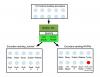
What do you think about it?
Best regards
Marxon
EDIT:
Maybe it´s better to move this post to the MidiboxNG section.
-
Hallo Rolf,
es ist wirklich interessant, deinem Synth beim Erwachsenwerden zuzusehen!
Mich würde noch interessieren, auf was sich die Bautteilkosten
beim aktuellen Stand des Gerätes belaufen?
Gruß
Marxon
-
...YAR for TK (yet another reminder)
:)
Best regards
Marxon
-
+1 for this idea!
Best regards
Marxon
-
Hi Alchemist,
- The regulator part: IC3, X1, C5 and C6 (power through J2)- The LCD part: P1, P2, T1, R4 (and R3?), but well use 1N4148 diodes for the CAN bus
- The MIDI part: R5, R6, R7, R8, R11, D1 (recycled for CAN bus), IC2, J12, J13?
- The DIN/DOUT buses: J8 and J9
- The AIN/AOUT buses: J6 and J7
Is it correct?
AFAIK you can leave out these parts except R9 and R10.
EDIT: and do I need 1 banckstick per core, or is it shared from core #1 to other cores?You can connect up to 8 Banksticks to one core.
They are shared between all cores.
Best regards
Marxon
-
OK i might have known it... :blush:
Thanks for clarification.
-
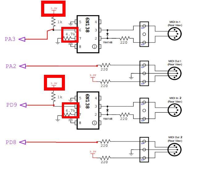
Ok thank you ilmenator!
Does it make a difference if i connect
the optocuppler Pin 6 to 5V instead of 3,3V
and if i use a 5,6k instead of a 4,7k resistor
like in older schematics?

Strange USB power voltage / no midi 3/4
in Testing/Troubleshooting
Posted
I meant to measure directly on the Mac USB port.
If there is really a 6V output then might something wrong with your Mac.