

Wisefire
-
Posts
416 -
Joined
-
Last visited
-
Days Won
1
Content Type
Profiles
Forums
Blogs
Gallery
Posts posted by Wisefire
-
-
After coming back to this issue every once in a while (real life stuff keeps popping up) it just occurred to me that I was most likely using older pic processor back then. in the mean time i've ordered a pickit from ali. Once I find a bit of time, i'll go through my older pic processors to see if I still have an older one. and see if i'm able to program it with the bootloader.
-
I do hope nobody minds me resurrecting this ancient thread. I finally started on that 8 out relay thing (9 years, damn!) i've mostly got the hardware built.
But i've been halted by bit of an issue.i've uploaded the j5_dout example hex to my core8, but the core8 doesn't seem to react to the midi note c4->c5 that i send it through mios studio. i've tried measuring it with my multimeter, and an oscilloscope, but only got 0v on the pins.
the core announces itself dutifully through Mios Studio, so i know the core is working. I've got multiple cores lying around, so i tried it with another one as well.
What am i missing?
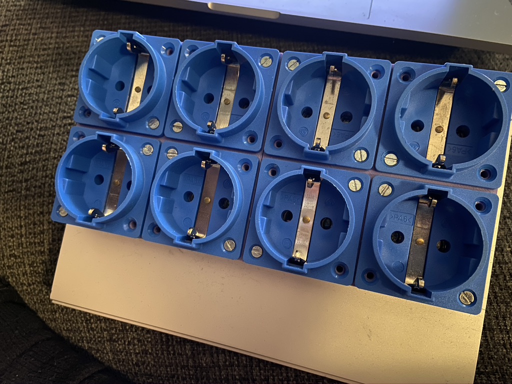
ps. sorry for the lack of pictures, as a meagre solace, here is the one i'm currently building.

-
i might be interested. still available?
-
ik heb besloten de backlog eerst maar eens af te maken, voor zover ze nog relevant zijn. en te kijken naar wat ik werkelijk nodig heb (maar het is allemaal zo mooi :P )
-
@NLX, hahah, heel herkenbaar idd. ik heb dozen vol met onafgemaakte projectjes, maar mijn MB_SID is toch wel de main one. die moet nou eindelijk 'ns af. :P
@shruriken no worries, sowieso tof dat er zo'n community spirit leeft.
-
hey NLX!
thnx voor de tip! Electruck heeft me er mee geholpen, maar wel leuk om te horen dat er nog steeds actieve nederlandse midiboxers zijn. :D
-
You can connect what you want for your CS, i've used it without any cs in the past!
-
Hey Roel,
Bedankt voor je aanbod! Opsturen is te doen, maar mocht er een midiboxer in amsterdam wonen is dat uiteraard makkelijker. Mocht ik na t weekend geen verdere replies krijgen dan zal ik je ff pm'en voor de details.
-
Hoi,
is er iemand in de buurt van amsterdam die toevallig die een PIC18F4685 kan branden?
groetjes,
Ysbrand -
oh, WOW, there is a special blog section now. i'll cease to clutter the forums and will be posting further updates on my blog.
-
Hey TK, Wintertime it is! Good to see the MB community still alive and kicking! And glad to be back.
-
And the IC headers.
-
Hi all,
I am wisefire. I was kind of active on here a long time ago, and I promised that one day i'll be back to complete (and document) my Midibox SID.Well the time has come to build it.
I have the version of wilbas MB6582 core board directly from wilba.
The idea back when I bought it was to build my own control surface around it, to be honest if I could make that choice right now I wouldn't be so sure, but i've got all the buttons and stuff for it already so let's start this adventure!
Soldering the resistors was first, here is a timelapse.
The next evening came the capacitors.
i'll keep you guys posted!
-
well, the thing is finished. and on time i must add..
the example code was exactly what i needed, i didnt even have to adapt it.. thnx TK!!!!
the relays i had work perfectly.. no opto or extra relays needed..
ill post some pictures later..
-
Hey TK! glad to be back! thank you for the example code.. its exactly what i was looking for!!
these reed relays are a good idea.. however ordering from reichelt would take way too long, and i would have to order for 100 euros at once.. i did have a look around to see if i could find it in one of our electronics stores.. and i did find some dual in reed relays/normally closed.. but i needed to by 25 of them..
i took a closer look at the datasheet for the relays ive already ordered.. and from what i can gather.. they already have an optocoupler in them.. these are pretty expensive relays.. solid state.. a led already on them, to show the state.. and i have no clue what a varistor is.. but they have it too.. im guessing they'll either be perfect for what i want to do with them, or it'll go horribly wrong.. either way. it'll be fun..
So the last thing is putting it all together.. i'll keep this thread updated.. and ultimately (when i have more time, i.e. a deadline that is more than 3 days away) i'll build a final box with 8 outputs and some cool code to automate stuff.. and ofcourse i'll post it all on the forums..
-
these are definitely some good suggestions.. so i'll be in need of some optocouplers.. gonna need to find an electronics store nearby.. my idea was to use some kind of resistor in series with the relay to limit the current..
here is the datasheet:http://www.produktinfo.conrad.com/datenblaetter/500000-524999/505395-da-01-en-HALBLEITER_REL_1S_15_A_250_VDC_AQA211VL.pdf
for the relais i'm planning to use.. they say its a MAX of 20mA for the input current.. i wonder what would happen if i put in a led and resistor in series though.. as for back emf and stuff like that.. isnt that for mechanical relays.. this one is AFAIK solid state relay, or however they are called..
as for that demo app.. nils.. would you happen to have a link to that? would love to get my hands on it..
-
ive written some beginners code for mios before so, its not a problem if i need to write it myself(famous last words :S) however i need the right code to command the pins to do what i want.. but if its possible within the MB_CV then i should be able to do it aswell.. hopefully the CV isnt written in ASM.. cuz that stuff is way beyond me..
maybe someone knows of some example code? i didnt find it.. but maybe someone did?
-
temporary return from midibox retirement.. i will come back soon.. but too busy right now doing other stuff.. however right now i have a little project where i want to ultimately drive 2 strobos with midi and i thought i could build it with midibox.. without realizing that i have been absent from the community for about 4 or 5 years.. luckily i still have a core_r3 lying around.. but my knowledge is dated and rusty.. and i have a specific deadline of a week.. yeah im insane.. but i think i can, i think i can, i think i can... *yeah, just keep repeating that.. that'll work*
so, i did a quick search.. and i know i've kinda asked it before (but with leds the other time)
is there a way to drive a relay without using a dout.. i just need to switch a signal from low to high, whenever a specific note comes in.. i dont have a DOUT lying around.. so i kinda wanna make it work without harvesting it from my already built gear..
i guess i just need 4V from a digital out pin somewhere, but last time i checked (5 years ago) there is no option in MIOS to drive a digital pin directly.. anyone an idea?
-
wait until smash finishes his mega sale for sid v2 parts.. or has he already, and ive been skipped..
could've very well happened.. ive been away for so long..
-
good point dude, right now i'm pretty busy with other stuff. just attended the ICMC08(international computer music conference) and june next year im going to NIME(new interfaces for musical expression)..
i'm trying to get my life online.. cuz right now i'm stuck in a dead end job, which bears no relation to my actual working field(??) which is sound composition and studio technology.. i'm trying to get ahead in those fields, and thats why i've retired from midibox for a while.. when i get the parts for my sid v2 from smashtv (its taking an awfully long time btw) ill get going again.. so until then..
i've got the MB_FM parts lying around, just no time to get them in a box and test it all..
thnx 4 your consern though.. glad to know i'm not forgotten :D
-
de prijzen van schaefer ligt aan hoeveel gaten, dikte materiaal etc.. gebruik frontpaneldesigner om te kijken hoeveel je design ongeveer gaat kosten..
-
No, that thread is called MB-6582 baseboard part kits
ROFLMAO, that is so fscking true!!
-
ive just received an PB, from someone who wondered if it was ok to hijack this thread to post his own build..
just to make it clear, my sid is not done yet, and i will be continuing this thread as soon as i get some free time again.
or when i get the parts from smashtv for the wilba PCB.
also its generally not a very good idea to mix builds.. as things tend to get convoluted..
for anyone beginning a new build.. make your own topic.. give a great name and start posting your updates..
you got a fresh topic, not some old dinky one with dents and scratchmarks from the previous owner.. no rust.. no old gum
wrappers on the floor.. well you catch my drift.. its easier to follow your build that way..
and of course good luck with your build..
-
id rather call it interaction design..
or you could call it interface design..
driving a relay without dout
in MIOS programming (C)
Posted
i am just stupid, that's what the issue was, or more like i was a bit conceited. thought i could pick up where i left off and have all my knowledge intact..
i FORGOT to upload the MIOS hex first.... yep, that IS dumb..
alright. so now, i'm facing other issues. i keep getting errors when uploading mios to some of my pics. i got just one of my 18f452 pics to accept mios.
cool, so i have 1 pic that should work. but when i plug the mb_core into the header of the relay board, only 7 relays are working. not 8.
so pin testing time, only 7 of the 8 pins output 5V. weird. bad PIC? alright, lets try my hand at programming the bootloader on one of my virgin 18f352, pickit3. nope. borrowed pickit2. nope.. oh hey an old 18f4685 in my stash, with bootloader!!! alright lets upload mios to that one..
success!!! buuuuut... only 7 of the 8 pins outputs 5V. WTF???
possible causes.
issue: 1 relay doesnt switch.
Could it be a faulty relay?
- no, inverting the sil socket cable, moves the issue to another relay.
Faulty cable?
- could be, but testing directly on the mb_core shows that that specific pin wont give 5v.
bad pic then?
- maybe, but 2 different types of pic have the same issue on the same pin.
Bad mb core PCB?
- no, tried multiple, besides i've measured continuity.
Bad source code - i'm not willing to believe TK wrote it incorrectly and didn't tested it, but for a learning experience let me see if i can check it with my limited knowledge.... nope it's mostly in assembly as far as i can tell. got as far as the function J5_IO_PinSet which can be found in the j5_io.inc file. dope, but it has more than 8 pins listed there, but it seems to forward those pins to the other pins if certain conditions are met. pin numbers seem to be in WREG, couldnt find that though. and even then, i wouldnt know what to do with it.
TL;DR - found a solution for the problem in my previous post (i was dumb), new issue, pin a0 on j5 won't output 5v after booting like the other pins, and doesn't react when sending C4 to the MB_core, the other pins work like expected.