

VilladonEnt
-
Posts
50 -
Joined
-
Last visited
Never
Content Type
Profiles
Forums
Blogs
Gallery
Posts posted by VilladonEnt
-
-
TK,
Just noticed that. I'll set them to '0' and reply back if that works.
Thanks,
VILLADON
-
Ok just to make sure I'm correct here, this is what I got:
4 Buttons, 2 Encs on SR2 of DIN
8 Buttons on SR3 of DIN
The built in LEDs on the 4 buttons are connected to SR1 DOUT
and the 8 buttons are connected to SR2 of DOUT
I made these changes with no success.
#define DEFAULT_DOUT_SR_PIN_01_08 1
#define DEFAULT_DOUT_SR_PIN_09_16 2
#define DEFAULT_DOUT_SR_PIN_17_24 0
The rest are set to '0' also
Any Ideas?
VILLADON
-
Humm maybe thats the problem..
I'm using SR's 1 and 2 on the Dout. and my .asm file looks identical to the one you just posted.
I'm sure I should change those. ;D
Thanks again,
I promise I'll get better.. ::)
VILLADON
-
I'm using the buttons in On/Off mode.
If they use the same routines then I can't see what else I could be doing wrong.
I also tried the dout inc/dec app in the troubleshooting section and that seemed to work also.
Thanks again,
VILLADON
-
Dear Thorsten,
I tried those settings in the MB64e ini file and i still can't get the lights to go out :-\
I was playing around all night long trying different settings in that file and still no go.
Here is what I did.
1) Downloaded MB64e application and sent to my box.
2) Downloaded Mksyx and sent the MB64e ini file to my box with the settings you suggested.
Since Traktor dosent send out midi msg I didn't think using the midi status received would do what I want, but I tried anyways. (But maybe I don't understand fully)
I did however download the midio128 Application and i was able to push a button on my box and the light went on but then went out when i released the button. Unfortunately I don't want to use that application. I need the MB64e Application.
If you can find a little extra time in your schedule to help me make some changes to the MB64e app.
I would very much appreciate it. I'm getting frustrated because I don't want to continue finishing my box (Designing the rest of my boards) until I understand fully what I'm doing with the led situation. :)
One mistake i know i did and have to correct, is connecting the buttons on the din with the with the
same pinning on the dout. because when i used the midio128 application, I would press a button and a light from a different button lit up.
Thanks again,
VILLADON
-
Thanks TK
I will try this soon as i'm home from work. Just wondering though, I have 4 Buttons and 2 encoders connected to one SR will this be ok? (Also on other SR's there is a mixture of buttons and encoders)
VILLADON
-
Traktor should be prefered, so that the LED is always in-sync with the host setup
Hello TK,
Yes I have Traktor set to toggle. But I'm now trying to get the code that toggles my leds on/off when i press a button on my box.
I was taking a look at the ain64_din128_dout128_v1_3 app, and was wondering if i could insert the whole
USER_DIN_NotifyToggle section of that app into the MB64E app and would that solve my issue.
This is why i thought maybe it can work.
Thanks,
VILLADON
;; now toggle the appr. DOUT LEDmovf TMP3, W ; button number has been saved in TMP3. This is also the LED number
IFCLR TMP4, 0, call MIOS_DOUT_PinSet1 ; if button has been pressed (value = 0V = CLR): LED on
IFSET TMP4, 0, call MIOS_DOUT_PinSet0 ; if button has been depressed (value = 5V = SET): LED off
-
Hello again,
Hey Thanks for the info on that mksyx and the ini file, I played around with that file and was able to make quick changes which i thought was
pretty cool. But I still cant figure out how to turn off the leds when i hit a button. I tried what you mentioned above but no go. I have already set traktor to
toggle mode on those buttons so setting toggle in the ini file makes me have to press the button one more time to actually make traktor respond to the button
press.
If you have any more ideas let me know.
Thanks again.
VILLADON
-
Hi Gerorge,
[bUTTONS] section of the iniI have the MB64E application and I don't see any .ini files anywhere. I Only see .inc files.
Thanks,
VILLADON
-
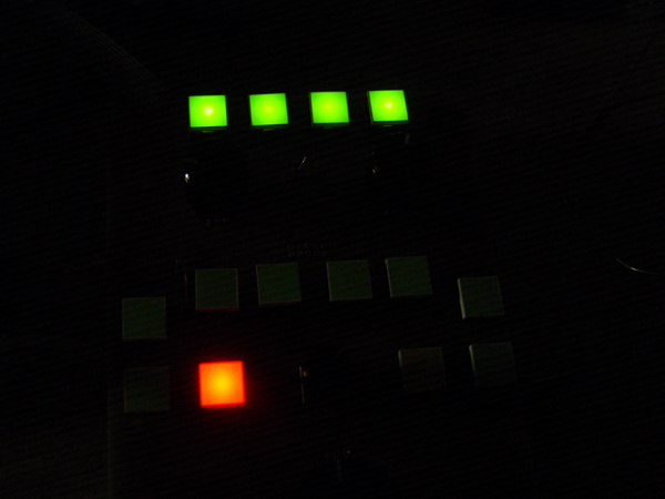
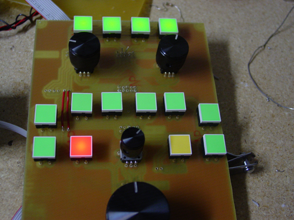
Hello All,
Today I'm testing out a board I made for my traktor controller (MB64E) .
As you can see when i plug my board into one of the SR's of the DOUT Module the lights are lit up.
I only want them to light up when i press them and go out when i press them again.
I searched through the main.asm file and a few other files in the MB64E application but I cant find where to set these prefrences.
say I have a button connected to SR2 Pin 0 on the DIN Module what corresponding pin must I have the LED connected to on the DOUT Module?
Thanks Alot,
VILLADON


-
Hi,
I had a similar problem because by buttons were connected to SR1 of the DIN, which I believe are used for menu navigation.
You may want to try to connect to another Shift Register and see what happens.
Hope this helps.
Villadon.
-
Thanks Illogik
I was almost totally confused until you edited the post :D
Thanks! everything is clear now!
Villadon
-
Hello All,
I've been looking around the forum for some answers but I can't find a straight forword example on Shift Registers.
What I'm looking to do is assign 2 encoders to J5 of the din and 4 buttons to J7 of the same Din.
I've played around with mios_tables_inc but can not get both working.
here is what i changed:
;; SR Pin Mode
ENC_ENTRY 2, 0, MIOS_ENC_MODE_DETENTED2 ; V-Pot 1
ENC_ENTRY 2, 2, MIOS_ENC_MODE_DETENTED2 ; V-Pot 2
ENC_ENTRY 2, 4, MIOS_ENC_MODE_DETENTED2 ; V-Pot 3
ENC_ENTRY 2, 6, MIOS_ENC_MODE_DETENTED2 ; V-Pot 4
left the rest as ENC_EOT
Is J5/J6 SR2? , J7/J8 SR3? , J9/J10 SR4?
Thanks,
Villadon
-
Thanks drin,
I'll be sure to post on the wiki after i test the first board.
villadon
-
Thanks Guys
Wasn't sure if he did or not. I bought (4) of the R2 versions a while back and I hated crimping (Could never get it right). So I figured I'd use the new layout
and use the IDC connectors instead. His store has been closed for some weeks now and I was just going to order again (can't beat his prices ;)). What I was
really planning out was to make a couple on a large clad and tie them all together. Maybe I'll just play around with the R2 version and incorporate the new dual
row headers somehow since I have a Din that is not soldered yet. Hope he wouldn't mind.
Thanks again.
Villadon
-
Hello all,
I've been looking for a link for SmashTv's New version of the Dinx4 layout in eagle format.
I know he's pretty busy, So I was planning etching a couple myself. I tried the wiki on ucapps but
those links seem to fail. ???
Thanks
Villadon
-
Hi Again :D
If the forward voltage is the 4.5v to 6v values you stated already (are they blue or white??) then you can only put two in series.They are Green/Red/Yellow LEDs the specs are : IF = 20mA , VF typ. = 4.2v, VF max = 6.0v. The same for all colors.
VL = 4.2 + 4.2 , VL = 8.4
R = (12v - 8.4v) / 0.020
R = 3.6v / 0.020 = 180ohm
So I can drive 2 LEDs with one 180 Ohm Resistor. Correct?
I don't know why you have a 12v supplyWell I figured this would be ok, since i'm connecting 2 cores and a bunch of DINx4's for my MB64e. and also driving those LEDs mentioned above.
So what I understand so far I would be creating a circuit with 30 180 ohm resistors to drive 60 LEDs.
Thanks again for all your responses. I've learned so much from this forum!!
Villadon
-
Thank you guys for replying. :D
tying them into a +5v circuit is useful if your LEDs need to be always on.That's exactly what I want to do.
I've figured out which resistors I need if I was going that route But with 60 or so buttons I thought it would be easier to create a 5v circuit.
My confusion is the power supply supplying 1.25 A and the buttons only needing 15-20mA. Excuse me for the lack of knowledge here but how
is the easiest way to reduce the mA? So I don't get the 7805 too hot.
Thanks Again!
Villadon
-
Hello,
I am planning out a circuit to provide power to the built in LEDs in my switches. The specs on my LEDs are rated for 4.2v to 6v Max and 15mA - 20mA max.
My thought was to use a voltage regulator like the 7805 on my circuit board to supply 5v to the LEDs since that is in the range my LEDs are rated for. Also I noticed there are three pins on the regulator,
1 for incoming power, 1 for ground and 1 for outgoing power. Am I correct? I do have a spare 7805 handy. Would this be all I need to suppy the 5v? How many mA does the 7805 produce? I'm using a 12v 1250mA WallWart supply.
Thanks All!
Villadon
-
Thanks again,
Villadon
-
Thanks pay c !
I'll have to check that feature when I get home from work.
That is done in the midibox_64e menu settings correct?
Villadon
-
Hello all,
I just received some alps encoders with 24 detent and I'm figuring out how to get them connected.
Here is what I did so far:
1. Modified the mios_tables.inc > ENC_PIN_TABLE > set encoders 1-16 to MIOS_ENC_MODE_DETENTED2
2. Modified the setup_midibox64.asm > ENC_PIN_TABLE > set encoders 1-16 to MIOS_ENC_MODE_DETENTED2
3. Rebuilt the Application (No errors)
4. Uploaded the main.hex and then the setup_midibox64.HEX using MIOS Studio.
5. MIOS Rebooted
I tried connecting 1 encoder diffrent ways but it seems that when i turn the encoder it jumps from values 0 to 127 nothing in between.
I also tried setting the encoders to MIOS_ENC_MODE_DETENTED but same prob.
Thanks for your time :)
villadon
-
Well From reading another post i guess i can use AIN with MB64E.
Scatch my prev post. ;D
i'd have to edit the main.asm file correct?
Thanks again,
VILLADON
-
Hi again,
Well it looks like i wont be connecting 2 cores. From what I understand so far is that i will have to run MB64e from
one core and MB64 from the other because i still need 3 linear pots for cross fader etc..
I want to use encoders, buttons and i guess i'll have to use pots for the volume/crossfader. unless there is a way to use a MF for the cross fade ??? dont make sense though because traktor dosent transmit midi.
Thanks again,
VILLADON


DIN/DOUT Config
in MIDIbox HUIs
Posted
TK,
Works perfectly ;D
Thanks so much
One more question if you don't mind,
I'm using R3 DIN and DOUT boards from smash and the pins don't seem to match up 1:1
Example: When I have a button connected to D0 on the DIN, and the LED to D0 On the DOUT, the LED connected to D4 of the DOUT Lights up
Here is how they map out for me.
DIN DOUT
--------------
D0 >>> D4
D1 >>> D5
D2 >>> D6
D3 >>> D7
D4 >>> D3
D5 >>> D2
D6 >>> D1
D7 >>> D0
Is this an issue with my settings or is that the way to pinning is supposed to be.
Thanks a bunch,
VILLADON