
lylehaze
-
Posts
613 -
Joined
-
Last visited
Content Type
Profiles
Forums
Blogs
Gallery
Posts posted by lylehaze
-
-
Just got mine.. Virginia USA..
VERY nice looking boards,
Too bad I'll have to wait a while to get parts to stuff.
THANKS!!
Lyle
-
I'm with the rest..
I am REALLY looking forward to my new boards, but taking care of yourself and your family should come first.
Enjoy the holidays, spend time with the people you love, and we (and the lady in the post office) will still be here when you get back.
This message is the VERY FIRST message sent from my Raspberry Pi!.
-
Hey Fairlight,
Happy Birthday, man!
(I hope this doesn't break the TOS for bulk orders!!)

LyleHaze
-
Quite interesting really.
I've been "away" for a while now, developing lots of MIDI-related stuff for AmigaOS 4.x.I'm quite proud of the flexibility of our existing MIDI routing library (CAMD), and theUSB drivers too. I have been wondering when I might look into OSC, even if it's justto expand the range of connections we offer.
One very nice possibility: I have always believed that the best use of the MBMixeris to remove the need for long audio snakes running from stage to the mix boothand back again.. If the actual mixer were located backstage, but the controls were"remote" from the booth, then LOTS of copper can be saved..
Ethernet would be a far better medium than MIDI to cover that distance.. and theslight cost in time wouldn't matter much at all.
This may be the "good reason" to move the MBMixer code to a newer core. ;)
TK, Thanks for sharing your work with all of us!
LyleHaze
-
For my future panel I'm thinking black anodized alu, with big holes around the encoders and matching "smoke" acrylic inserts to view the LEDs through (a bit similar to an LCD window but now with a hole in the center to poke the encoder shaft through).
How about home-cast clear knobs that are big enough to show the LED ring under them?Might look cool, though a bit big..?
-
I need to expand my rack to 8U, but taking the BCR off the top should save that much space.I was digging in my junkbox last night for some resistors, and came across an unfinished project that would receive and decode a remote control into MIDI volume messages.
This looks like a good time to finish that project.
I really like the translucent panel idea, that should reduce the panel holes to 16 + 4 for mounting.
I just can't decide what color LED's and plexi.. something to think about.
LyleHaze
-
Now THAT is a nice bit of work.I've been driving the MBMixer with a BCR deck for years now, and it got damaged in a trip two weeks ago.
So now I get a MidiBox control surface to match my mixer? Sweet!
I just signed up for two boards with resistors, if there is any trouble reaching me, just usemy_nickname at gmail.com.
Merry Christmas to all!

-
Thanks,that's exactly the file I was seeking.
I'll be traveling this week, adn bringing my MIDI gear for demonstration.
Might as well use the display on the MBMixer as a scrolling message board!
LyleHaze
-
Greetings,
I have an 18F Core8 project that includes a 2X20 character LCD display.Tonight I went looking for the details on how to format a SysEx message thatwill display text on that display.I did it before, but can't find the utility I wrote.
I checked the WIKI, and didn't find much. (maybe I did a bad search?)I checked uCapps, and found a link to the document I need!http://uCapps.demios/mios_sysex_implementation.txt
Sadly, the link only leads to a 404, file not found.
Any suggestions on where I can find this information?
Thanks,LyleHaze
-
Thanks lylehaze. I based the schematic on the relevant part of the MIDIbox LTC module: http://www.ucapps.de/mbhp_ltc.html, so figured that it would be OK. Do you have any suggestion as to how to protect the inputs of the gates?
Thanks,
Kevin
I'd try to avoid any negative voltages in the first place. The attached drawing is untested, PLEASE build a test circuit and experiment with the R and C values before committing anything.Without any timing delays, you get such a brief flicker of light that it's hard to see. So the question becomes, how long should a minimum flash length be? You get a longer LED ON timeby increasing resistor ohms OR increasing capacitor uf. Lesser values for either will make a shorter flash.I drew this using inverters, you may use NAND gates instead if you want, just gang both inputs together.Bonus Design goal: CMOS chips WILL operate in the linear region (as they do in this circuit), but they draw less power when run with hard ON or OFF signals.. You can get that by using this same circuit but choosing inverters with "schmitt trigger" inputs. Basically these are inputs that "snap" high or low when the input voltage is wandering around in between. What you get in return is a bit less power draw and LED's that are ON or OFF instead of some (minor) "fading" during the delay portion.
Please experiment before deciding what values of R and C to use.. I just threw some random numbers into the simulator.
Have Fun.

-
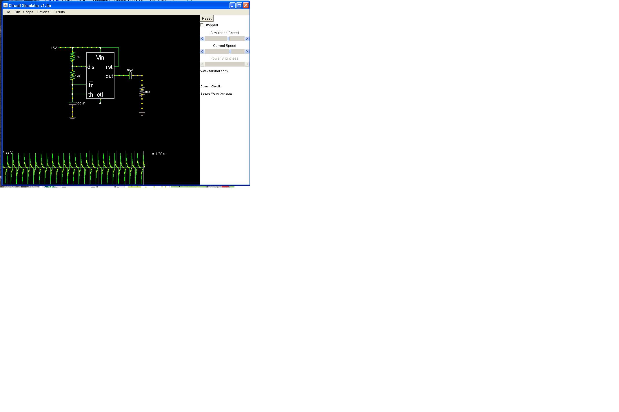
I have attached a screen grab from the java circuit simulator to help show why.The sim is at falstad.com.. under analog circuit simulator, 555 timer, square wave generator if you want to have a play.
To show the problem, I attached a capacitor in series to the square wave output, then a resistor to ground. this is the same arrangement you have between the lower and upper NAND gates.The scope trace at the bottom shows the problem. Every time the square wave falls from 5v to 0v, you get a negative voltage spike of over 4 volts (actually, that would be UNDER -4 volts).
The datasheets of most chips require all voltages to stay between V+ and V-, or in this case 5V and Ground.
There _ARE_ built-in diodes at each input to the chip to help protect the chip from damage, but these are last-ditch protection devices, and it's not a good idea to design a circuit that requires this protection to avoid frying the chip. The particular HC00 datasheet that I looked up (no link, sorry) even puts a statement near the top of the page specifying that you should never depend on the protection diodes to save you.
Most chip datasheets offer two sets of limits.. "operating" conditions and "absolute maximum" conditions. The difference is simple.. the chip may fail outside the operating conditions, the chip may suffer permanent damage outside the "absolute maximum" conditions. As you might guess, the requirement to keep all inputs between VCC and VSS is an absolute maximum condition.
I hope this has helped to explain my previous comments.
LyleHaze

-
I am also looking to add activity LEDs. I have come up with a schematic based on the LTC module, but with what I assume are unnecessary parts removed. Could someone please confirm that this is all I need.

Thanks,
Kevin
As drawn, this circuit will drive negative spikes to the inputs of the "upper" NAND gates.The built-in protection diodes will help, but it's hard to say how long they will last before the HC00 chip just dies,
-
I just checked on DigiKey for rotary optical encoders.. They offer anything from 8 to 2048 pulses per revolution.Opticals are a bit more expensive but might last forever. I think I paid about $20 for the one I'm using here.
Have fun,LyleHaze
-
My second question is about the midibox mixer project..
From what I understand the midibox mixer is a midibox that would allow midi messages to be sent, as well as input and output audio. (Please correct me if I am wrong)
I am wondering then if it would be possible to create a midibox, and then later add functionality to it and switch to midibox mixer, or is there something in the design process that would not allow it.
Ideally I want to make a midi controller for dj'ing that would have 4 audio channels output (or is mbmixer only ins?) 2 going to my main output, and then 2 going to a stereo output for cueing tracks to headphones.
-Matt
The Midibox mixer will mix analog audio, and can be configured for two separate stereo outputs. (one for mains, the other for headphones). It can support up to 16 stereo pairs input.
It should NOT be used as a control surface, it would be far better to use a second core to manage your controls. This would also allow separation of the controls and the audio mix section, as well as the ability to record and play back the mix using any sequencer. I also have control windows using java on a PC, or native code for AmigaOS4. Normally, I have ALL of these methods "in control" at once, with all changes being echoed back to all the various control points. (Amigas are very flexible with MIDI handling)
When I completed the project, SmashTV helped me with a final board re-design, and I had hoped he could carry the boards in his webshop. Unfortunately the economy took a deep dive, and the community has moved on to other core designs.
I still have the original "version 2" mixer as shown in the Wiki, and it still gets used every single day. It's a very versatile mixer, and it even fits into a 1U case! I promised Smash exclusive access to the board designs, and I haven't heard from him in a while. I am good to my word, and will not release the board files to anyone else. (besides, he has the better version that we collaborated on, I don't).
It is great to hear that there is still interest in the project. Though I'm now quite busy doing coding for AmigaOS4, I try to stop by here every day or so.
I am confident that the mixer could be ported easily to any of the other cores, and probably re-written in C as well, without much trouble. It's actually just a bunch of simple math to create a mixer model.
The future of the project from here would have to start with boards, but if they become available, the code and the original coder will be available. :)
LyleHaze
-
I would suggest keeping all grounds connected at all times. Switch the other lines, but keep all grounds connected.
LyleHaze
-
You could watch MIDI messages and guess at the level of the resulting audio output.
Including CC#7 and velocity information could make it more accurate, but in the end, you'll have a guess. You cannot predict the ADSR envelope of the audio by watching the MIDI stream, so you won't really be watching the audio level, just an estimation based on the MIDI events that triggered it.
There are easy, single-chip VU meter drivers that have audio inputs, and a group of LEDs driven directly from the chip. These require actually connecting to the audio signal.
Another method that I considered (but never built, yet), is a simple sample/hold circuit connected to an AIN, which would allow you to read the audio level directly into a core. Then you could output a MIDI stream to a remote meter or display. As I mentioned in another thread, this would also allow a software-driven AGC if you also have a MIDI controlled mixer. Software filtering of the meter stream would also allow user-configurable VU damping control.(fast, medium or "peak" response meters)
In any case, if you want to see the actual sound level, you'll need to monitor the actual audio signal.. Unless someone knows a better way..??
Have Fun,
LyleHaze
-
OK.. NE5532 is a better part number.
The mix circuit: Balanced is most useful when signals are being carried some distance, to prevent interference.
Many people would use unbalanced signals "on board" and only use balanced for the final output.
The signal will be unbalanced going through the volume chips no matter what.
And a lot more people would just go unbalanced all the way.!
If you build TWO of this circuit, and call one "LEFT" and one "RIGHT":
http://www.midibox.o...=pga:ch1out.gif
And then connect a 10K resistor from EACH individual channel "Left" to the left screw input,
And then connect a 10K resistor from each individual "RIGHT" output to the right screw input,
then you will have a full stereo mixer, with balanced or unbalanced outputs for left and right.
And that is from one "haze" to another.

p.s. that is a bipolar circuit, it requires both + and - voltage to power it.
-
b> Good to know, i didn't noticed this when i read the datasheet - i will add balance for each stereo channel this way !
e> ok then , i wasn't sure but now you tell me it becomes more clear.
a) Then my problem is how to combine the 16 channels? just soldering the mixed outputs together will combine them ?
b) Do i need a special audio processing component to combine the 16 channels ?
j> So if the serial control is adressed I2C , i need to make a channel board with a separate PIC on each in order to be able to chain the audio modules .
a) wich kind of PIC do you advice me , my goal was to obtain chained audio modules controlled by one core (see my drawing on my first post), as the I2C MIDI modules are.
b) is PIC programming for I2C port adressing hard to make ? i mean will i need to deal with complex ASM?
thanks in advance for your answers,
cheers,
Jerome aka psykhaze
e> You can do it with just resistors, with a lot of loss in output level, or you can do it with a single op-amp per output channel and a bunch of resistors, for unbalanced outputs, or with two op-amps and some resistors per channel, for balanced outputs.
Don't be afraid of op-amps, they are pretty easy to figure out. A simple 8 pin DIP chip can provide two op-amps. So one little 8 pin DIP can mix left and right, unbalanced. 2 can make left and right balanced. There are many to choose from, I am using 5532's here.
It is possible to "bit-bang" I2C outputs, so you can get more than one per core, but this requires a bit more programming. These chips are not expensive, so maybe one per channel strip would be easier.
You could "network" them by MIDI to make life easier, as all the different boards you choose (PIC or otherwise) can do MIDI easily.
Everything in engineering is about compromise.. making choices to get what you want without too much trouble.
At this point you have a LOT of choices, and each one will affect all the others, as well as the final project cost and capability.
The better you know what you want, the closer you can get to it. The more study you do first, the less surprises you'll get later.
The answers I give are not the "BEST" ways, just what worked best for me.
Most of all, Have Fun!
LyleHaze
-
b) TDA7439 doesn't offer panning control, as it even offers tone control , so another component will be required to control only panning - do not sure i will include first but would like to solve the problem
e) Modular chained modules was my goal, but keep in mind that the TDA7439 mixes a group of 4 stereo channels. Then you have to make a "main" mix between the groups of 4 stereo channels to get your master mix , it's like a tree
b> The TDA chip offers panning by individually controlling the last gain stages,"Speaker Attenuation", separately for left and right outputs. If the inputs are stereo, it's balance. If a mono signal is fed to both channels, it becomes pan. Step Size, 1dB
e> The TDA does NOT mix 4 pairs.. It selects ONE of 4, then mixes that ONE pair.. It will NOT combine them for you. It's NOT a tree, it's volume and tone for a SINGLE audio pair. It's real important that you understand this.
Also, the reason I came back.. The serial control is addressed I2C, so you will NOT be able to "daisy chain" a bunch of chips together like the PGAs. You'll need a separate I2C port for each chip, as the addresses all match, and can not be changed.
This is not a problem if you're building channel boards with a separate PIC on each strip... but that may not be what you had in mind.
Have Fun,
LyleHaze
-
Those TDA chips are a nice find! I don't think they were available the last time I was doing audio processing. :)
If I were to compare them directly to the PGA chips from a previous mixer project, there are a few points in each direction:
Good Points:
These include input multiplexers which the PGA chips do not. And they are "broken out" so you can get tricky if you want!
The tone controls are an obvious improvement (OK, I'm a bit jealous!)
The chips are MUCH more affordable than the PGA4311 chips are.
Not so good points:
The attenuation range is much smaller, and the step size is twice what the PGAs are.
The configuration is less flexible, it will take two chips per pair if you want to support Effect Sends.
I don't see any option for zero-cross switching, so the changes might be a bit noisy.
But they are certainly a viable choice!
On to a few of your questions:
C vs ASM: Whatever you are most comfortable with.
TDA datasheet understanding: It looks nice, but will need twice as many chips as PGA would. If you want details, just ask.
Cores needed: I didn't check the details, but you can probably do whatever you want. Latency WILL grow as chip count goes up. When it exceeds 1 MIDI byte-time, problems may begin.
Interested? I have some experience, and would be happy to help, but I probably will not get too involved, as I already have a MIDI mixer that's working fine.
Advice? Sure!
Everything Hawkeye said is a great start. I'll repeat something then add some more:
DEFINITELY separate the mixer from the control surface. There are many reasons why. If you REALLY want them together, make them as COMPLETELY SEPARATE projects sharing a single box. That way it'll be easy to separate them later.
VU meters are a great idea, but if you really want "cool", have the audio side read levels with Ainputs, and output the current levels as a MIDI stream. Then you can have REMOTE VU meters, or "soft" meters on an attached computer, or use external software to read the meters and adjust the levels (programmable AGC) and lots of other cool stuff.
I don't stop by here as often as I used to. I'm writing MIDI software for a bigger box now. But you are welcome to E-Mail me for further discussion.
I can be reached using my nickname at gmail.
Oh, you think MBMixer V2 is outdated?? It's been working great for years, and is actually in use at least 12 hours a day, seven days a week.

Have Fun,
LyleHaze
-
One of the best things about this thread is that ALL the posts are correct, everything makes sense, and there are no arguments about which is "better".
Engineering is a series of compromises.
Have Fun!
LyleHaze
-
The protection diodes are a good idea, especially if you are using unusually large capacitors after the regulators, as you are in this case. The "dangerous condition" is after power is removed, the voltage at the output of the regulator will be greater than the voltage at the input.
Why did you do this on some regulators but not all of them?
AGND and DGND should be connected in one place. and the power supply is usually that place.
D5 drops the voltage to the 7805 just a bit. this means it will run just a bit cooler, and the heat from D5 is exactly that amount. In the end, net heat is the same either way.
A suggestion: Instead of using 2 pin SIL for the +5 outputs, use 3 pin with the center grounded and BOTH outside pins at +5 volts. This means less chance of plugging it in backwards, but more likely to get it confused with the 12 volt connectors..
Have fun!
LyleHaze
-
Most of the errors are because of "processor mismatch"
The code claims to be built for a specific chip, but the menus of MPLAB are set for some different chip.
Originally, the code would define which chip it was intended for..
Then at some point along the evolution of MPLAB, the user was expected to use menus to select which chip the build was for.
So now it is supposed to support BOTH styles, and it will complain if they do not match.
That's all the warnings anyway.. then there is the following error:
Error - could not find definition of symbol '_USBDSC_DEVICE' in file './usbdrv.o'.
Which you'll have to look into yourself. Getting the right processor definitions might fix that too.
Have Fun,
LyleHaze
-
While it would (I suppose) be overkill, if you wanted to use the newer STM32 based CORE32 rather than the CORE8, you could use Jonathan Farmer's dpot (Digital Potentiometer) driver.
Digital Potentiometers work in a similar way to their analogue counterparts but are controlled by an SPI interface rather than fingers :)
At the risk of going too far off-topic, most digital pots require all connected signals to be between the supply rails of the chip.
In the case of the chips you mentioned, this means the audio signals have to stay between 0 and +5 volts. Since an audio signal is AC, this means you'll have to add a DC offset before the digipot, then block the DC offset afterwards to get back to an AC signal.
This is an often overlooked restriction on analog pots. You can find all of this in the device datasheet.
LyleHaze

Damaged MIDI/USB port on Circuit board - power but no data between laptop
in Testing/Troubleshooting
Posted
First,
Nice job on getting a decent photograph.
I continue to be pleasantly surprised at how technology is changing everyday life.
Most people nowadays carry a networked communications device in their pocket, and most have one or multiple cameras attached. Back in the days of 300 baud acoustic modems that was all fantasy.
And on to your problem:
Newer "unleaded" solders have a slightly higher melting point than the leaded stuff, but it should not be enough to create a problem.
When a less experienced person attempts circuit board repair, the greatest chance of damage is from too much heat, causing de-lamination of the traces. Based on that alone, I'd say go gently, or ask a friend with more experience. "More Heat, Bigger Iron" would certainly increase the chances of more damage faster.
If you have other USB ports that work, an external hub might be the easiest way forward.
:)