lylehaze
-
Posts
613 -
Joined
-
Last visited
lylehaze's Achievements
MIDIbox Guru (4/4)
1
Reputation
-
 First, Nice job on getting a decent photograph. I continue to be pleasantly surprised at how technology is changing everyday life. Most people nowadays carry a networked communications device in their pocket, and most have one or multiple cameras attached. Back in the days of 300 baud acoustic modems that was all fantasy. And on to your problem: Newer "unleaded" solders have a slightly higher melting point than the leaded stuff, but it should not be enough to create a problem. When a less experienced person attempts circuit board repair, the greatest chance of damage is from too much heat, causing de-lamination of the traces. Based on that alone, I'd say go gently, or ask a friend with more experience. "More Heat, Bigger Iron" would certainly increase the chances of more damage faster. If you have other USB ports that work, an external hub might be the easiest way forward. :)
 -
Control surface PCB for 16 encoders/LEDrings Bulk Order
lylehaze replied to Fairlightiii's topic in Bulk Orders
Just got mine.. Virginia USA.. VERY nice looking boards, Too bad I'll have to wait a while to get parts to stuff. THANKS!! Lyle -
Control surface PCB for 16 encoders/LEDrings Bulk Order
lylehaze replied to Fairlightiii's topic in Bulk Orders
I'm with the rest.. I am REALLY looking forward to my new boards, but taking care of yourself and your family should come first. Enjoy the holidays, spend time with the people you love, and we (and the lady in the post office) will still be here when you get back. This message is the VERY FIRST message sent from my Raspberry Pi!. -
Control surface PCB for 16 encoders/LEDrings Bulk Order
lylehaze replied to Fairlightiii's topic in Bulk Orders
Hey Fairlight, Happy Birthday, man! (I hope this doesn't break the TOS for bulk orders!!) LyleHaze -
Quite interesting really. I've been "away" for a while now, developing lots of MIDI-related stuff for AmigaOS 4.x.I'm quite proud of the flexibility of our existing MIDI routing library (CAMD), and theUSB drivers too. I have been wondering when I might look into OSC, even if it's justto expand the range of connections we offer. One very nice possibility: I have always believed that the best use of the MBMixeris to remove the need for long audio snakes running from stage to the mix boothand back again.. If the actual mixer were located backstage, but the controls were"remote" from the booth, then LOTS of copper can be saved.. Ethernet would be a far better medium than MIDI to cover that distance.. and theslight cost in time wouldn't matter much at all. This may be the "good reason" to move the MBMixer code to a newer core. ;) TK, Thanks for sharing your work with all of us! LyleHaze
-
Control surface PCB for 16 encoders/LEDrings Bulk Order
lylehaze replied to Fairlightiii's topic in Bulk Orders
How about home-cast clear knobs that are big enough to show the LED ring under them?Might look cool, though a bit big..? -
Control surface PCB for 16 encoders/LEDrings Bulk Order
lylehaze replied to Fairlightiii's topic in Bulk Orders
I need to expand my rack to 8U, but taking the BCR off the top should save that much space.I was digging in my junkbox last night for some resistors, and came across an unfinished project that would receive and decode a remote control into MIDI volume messages. This looks like a good time to finish that project. I really like the translucent panel idea, that should reduce the panel holes to 16 + 4 for mounting. I just can't decide what color LED's and plexi.. something to think about. LyleHaze -
Control surface PCB for 16 encoders/LEDrings Bulk Order
lylehaze replied to Fairlightiii's topic in Bulk Orders
Now THAT is a nice bit of work.I've been driving the MBMixer with a BCR deck for years now, and it got damaged in a trip two weeks ago. So now I get a MidiBox control surface to match my mixer? Sweet! I just signed up for two boards with resistors, if there is any trouble reaching me, just usemy_nickname at gmail.com. Merry Christmas to all! -
Lost documentation for Core8 sysex implementation
lylehaze replied to lylehaze's topic in MIOS programming (C)
Thanks,that's exactly the file I was seeking. I'll be traveling this week, adn bringing my MIDI gear for demonstration. Might as well use the display on the MBMixer as a scrolling message board! LyleHaze -
Greetings, I have an 18F Core8 project that includes a 2X20 character LCD display.Tonight I went looking for the details on how to format a SysEx message thatwill display text on that display.I did it before, but can't find the utility I wrote. I checked the WIKI, and didn't find much. (maybe I did a bad search?)I checked uCapps, and found a link to the document I need!http://uCapps.demios/mios_sysex_implementation.txt Sadly, the link only leads to a 404, file not found. Any suggestions on where I can find this information? Thanks,LyleHaze
-
I'd try to avoid any negative voltages in the first place. The attached drawing is untested, PLEASE build a test circuit and experiment with the R and C values before committing anything.Without any timing delays, you get such a brief flicker of light that it's hard to see. So the question becomes, how long should a minimum flash length be? You get a longer LED ON timeby increasing resistor ohms OR increasing capacitor uf. Lesser values for either will make a shorter flash.I drew this using inverters, you may use NAND gates instead if you want, just gang both inputs together.Bonus Design goal: CMOS chips WILL operate in the linear region (as they do in this circuit), but they draw less power when run with hard ON or OFF signals.. You can get that by using this same circuit but choosing inverters with "schmitt trigger" inputs. Basically these are inputs that "snap" high or low when the input voltage is wandering around in between. What you get in return is a bit less power draw and LED's that are ON or OFF instead of some (minor) "fading" during the delay portion. Please experiment before deciding what values of R and C to use.. I just threw some random numbers into the simulator. Have Fun.

-
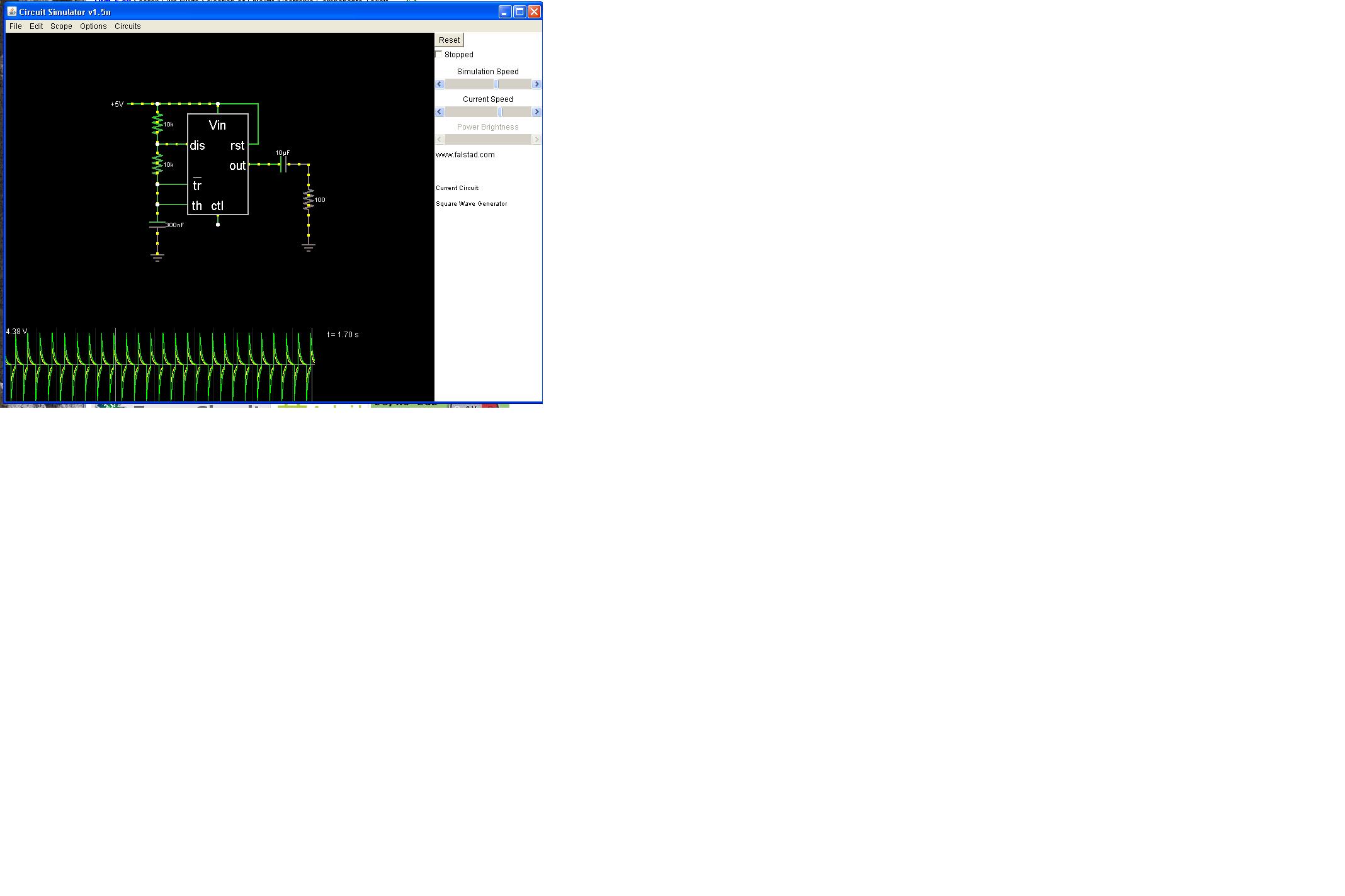
I have attached a screen grab from the java circuit simulator to help show why.The sim is at falstad.com.. under analog circuit simulator, 555 timer, square wave generator if you want to have a play. To show the problem, I attached a capacitor in series to the square wave output, then a resistor to ground. this is the same arrangement you have between the lower and upper NAND gates.The scope trace at the bottom shows the problem. Every time the square wave falls from 5v to 0v, you get a negative voltage spike of over 4 volts (actually, that would be UNDER -4 volts). The datasheets of most chips require all voltages to stay between V+ and V-, or in this case 5V and Ground. There _ARE_ built-in diodes at each input to the chip to help protect the chip from damage, but these are last-ditch protection devices, and it's not a good idea to design a circuit that requires this protection to avoid frying the chip. The particular HC00 datasheet that I looked up (no link, sorry) even puts a statement near the top of the page specifying that you should never depend on the protection diodes to save you. Most chip datasheets offer two sets of limits.. "operating" conditions and "absolute maximum" conditions. The difference is simple.. the chip may fail outside the operating conditions, the chip may suffer permanent damage outside the "absolute maximum" conditions. As you might guess, the requirement to keep all inputs between VCC and VSS is an absolute maximum condition. I hope this has helped to explain my previous comments. LyleHaze

-
As drawn, this circuit will drive negative spikes to the inputs of the "upper" NAND gates.The built-in protection diodes will help, but it's hard to say how long they will last before the HC00 chip just dies,
-
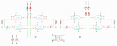 This circuit will operate the NAND gates outside of the input voltage range.Each of the 4 gates on the top half of the drawing will be driven with a negative voltage spike each time the LED is turned OFF.How long it lasts will be a matter of chance and luck.
 -
I just checked on DigiKey for rotary optical encoders.. They offer anything from 8 to 2048 pulses per revolution.Opticals are a bit more expensive but might last forever. I think I paid about $20 for the one I'm using here. Have fun,LyleHaze