

ris8_allo_zen0
-
Posts
173 -
Joined
-
Last visited
Content Type
Profiles
Forums
Blogs
Gallery
Posts posted by ris8_allo_zen0
-
-
Only after doing my mod/patch/hack I noticed Wilba made a similar thing in its MBSIDv2, so I was thinking about using the same format at least for SR number representation: adding 16 seems more clear, and even more for who wants to build both MBSIDv2 and the MBSEQ (like me ;) ).
In other words: expect soon a new version of the patch!
As attachment there's the table of the keyboard mapping layout I used. The numbers should be right for a normal C64 keyboard so they must be confirmed by someone else. Please note that I plan to put leds in place of the space key, which should be removed.
Best regards,
Enrico
-
LOL we are such geeks mate.... I thought the same thing.
I'm actually a little weirded out by that. I didn't even stop and think about it... I wonder if the pattern of characters gave us a subconcious hint?
I don't know! But I'm sure I saw a similar pattern once on my LCDs when I was driving crazy building the cable: I crimped the wires manually one by one and there were plenty of shorts & cuts... Terrible.
But a geek is a geek :D
-
I've thought of a way to do this: spray them all white on top, then attach some "text decals" like these (or have them made by a friend of mine which owns a cutting plotter), then black spray paint, then remove carefully the decals... et voilà ! White text on black curved surface!
Just a little problem: I have currently no experience about painting :)
Best regards, Enrico
-
My LCD reads: OKOS "V3.; g"""""3+Novg" C_2""" I know that this is not right. Is it possible that I have really messed this thing up?
Have a check somewhere between D0 and D1 pins/wires of J15. If I'm not wrong "OKOS" stands for "MIOS" with the second bit always set ;)
Best regards, Enrico
-
beside of that for those which are fans of C64 Keyboards and those which have built up a MBSEQV3 yet, my K64 application controls MBSEQV3's record and utility functions from outside via midi remote. That is another way to controll SEQ...
... and don't forget that K64 is good for anything than SEQv3 :)
P.S. new photos available at my Flickr page...
Best regards, Enrico
-
Hello midnite!
Did you read this thread?
http://www.midibox.org/forum/index.php?topic=5677.0
It should answer all your questions...
Best regards, Enrico
-
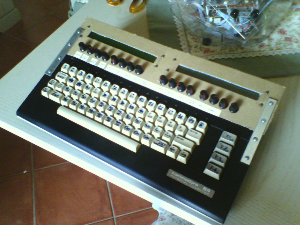
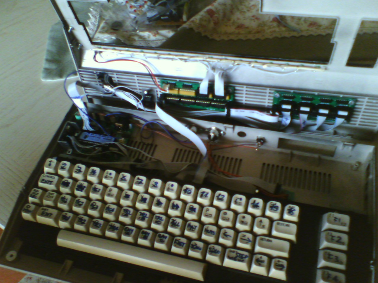
As promised, here are some pics of the thing. Please don't take much importance about the misaligned encoders, the keys renamed with a blue thick pencil, the carton panel and the poor quality of the cameraphone ;)
Best regards,
Enrico


-
The measures surprised me: with the transfo set to 7.5V, the real output voltage was 10.8V!! and when set to 6V, it was 8.2V (both values under load).
And the current drawn is around 0.25A. Isn't it too little to have a regulator+heatsink almost good enough to fry eggs while grooving? ;)
The Vd/Vs voltage is 4.96V with 4 leds turned on, and 4.88 with 16 leds (soon I'll add the remaining ones). Is that OK?
Yep, all that power needs POWER! ;D
You'd be happy to know that the power LED of the former-C64C (now "Commodoseq"?) now acts as beat indicator :D
Best regards,
Enrico
-
Heh, first thing I thought was BOR... but I couldn't think of a reason that only arp mode would do that, so I stayed quiet... ::)
I saw the problem in arp mode because I was drooling with that feature when I got the first crash :P
*BOR = Brown-Out Reset - When the power goes too low (a brownout) the PIC will reset itself. You'll probably know it if you see it, because it is very random, very sudden, and guaranteed to give you a bad sinking feeling in your gut when it happens the first time ;)
That feeling that suggests me I've worked hard for two months to have something that runs like Windoze :P but I see there's a good reason also for this symptom!
Yesterday evening my Seq runned with an heatsink for an hour without problems, but I still can't touch it nor the 7805, they're hot like hell... possible?
Best regards,
Enrico
-
Does the SEQ also reboot when not in Arpeggiator mode? If not, it´s a software issue. If yes, it might be PSU-related.
I did some other tests. In fact, it also crashes when not in Arpeggiator mode, unlike stated before. (last time it crashed I accidentally pressed Edit+GP2, which in fact does nothing special)
Then adding an heatsink should be the solution. Thanks, I'll let you know.
Best regards,
Enrico
-
7.5 volts 1A to power all the above plus one LCD backlight (the other one broken and was temporarly replaced with another non-backlit). The 7805 has currently no heatsink and gets very hot with that backlight, that's why I don't want to use 9V.
I also tried to modify the PCB to let the backlight use the unregulated supply, but for some error the same supply went also to LCD's Vd killing one of them. Now I reverted to original.
However, I remember the Vd is stable at 4.86V.
-
Hello everybody,
I found that my brand new SEQ reboots after some random time (about 2-3 minutes) while I use it as arpeggiator, doesn't matter if using an external keyboard or the loopback port.
I'm using the SmashTV board, 1 IIC, 6 EEPROMs and my custom "c64-keyboard" patch.
Any clues?...
Many thanks!!
Enrico
-
Somewhere in the way I deleted DOUT_ENTRY_EOT.
I'm collecting the worst & weirdest errors a MIDIbox nerd can do... :'( >:( ;D
-
Check the DEFAULT_SRM_CATHODES and DEFAULT_SRM_LEDS_DOUT settings, the overlay all other shift register assignments
DEFAULT_SRM_CATHODES is set to 8, indeed the modulation matrix works perfectly.
DEFAULT_SRM_LEDS_DOUT is set to 0, and I don't know what other value to use because I don't own the Wilba's layout...
-
======= 11 months elapsed from the last post =======
I experienced the same problem with 1.74685. It raises when AUTO_CS_ENABLED=0.
Using tarzan boy's typo hypotesis, I changed the code this way (line added is bold). It compiles well, but I can't say what will be the effects :P
[pre]
; --------------------------------------------------------------------------
CS_MENU_PRINT_DEV
#if AUTO_DEVICE_ID == 0
movf CS_MENU_SID, W
andlw 0x03
bnz CS_MENU_PRINT_DEV_Invalid
incf SID_MIDI_DEVICE, W
rgoto CS_MENU_PRINT_Dec
#endif
CS_MENU_PRINT_DEV_Invalid
rgoto CS_MENU_PRINT_Invalid
; --------------------------------------------------------------------------
[/pre]
Best regards,
Enrico
-
SOLVED! I have to say such things can happen only to me...
It was all a matter of CR-LF handling by MPASM. I've made the original setup on Linux, but now I'm using Windows. When I copied the entries from a file to another, the MPLAB IDE didn't care about converting Unix- to DOS-style line characters, so the assembler had a file with mixed format. I noticed it while analyzing the listing file. Solution: copy, paste into WordPad (which does a good conversion), then re-copy and paste into the other file.
Now all the inputs work perfectly, but now there's a little strange behaviour in the DOUTs: most LEDs flash "rhythmically" at regular intervals (different than while pressing the mod-matrix buttons) instead of staying on. At the moment I see no correlation between those Leds and their respective number or function... Tried recompiling and re-uploading, it's the same.
???
P.S. I'm using MIOS Studio beta7_5
Best regards,
Enrico
-
Did you upgrade to the latest MIOS, which included support for PIC18F4685?
Yes, to v1.9f.
You might want to also try the V2 beta instead, you might be lucky and the problem goes away ;D
That's what I hoped :) I did, but nothing new happened...
Or try merging into setup_tk.asm (which might have something different to setup_8580.asm which makes this problem go away)
Done. See above :(
Otherwise I'm a bit confused why it should be crashing. The DIN, DOUT and encoder tables should work identically to before, only by referencing a shift register by 16+1, 16+2 etc. will the SRM stuff get used. It should be 100% compatible to the current MB-SID control surface wiring (including any different wirings).
I tried to edit the button handler routine to only display on the LCD the hex code of the pressed button. The numbers are correct again.
After doing some other experiments, I discovered that only 2 of the 15 encoders work as expected: the data wheel and the Osc Delay. They even work when I change their pin assignment. I see they're the first two in the list... could this mean something?
Best regards,
Enrico
-
Hi all,
I was wondering if something in the SR chain changed with the 18F4685.
I ask this because while I was going to upgrade my MBSID from v1.7303 to v1.74685, I noticed all my DIN/DOUT configuration is completely messed up (e.g. each button doesn't have its right function anymore). LCD and MIDI still work well. I also tried to implement the ECAN support in the board (simply added the 1k pullup between Rx and Vd), but nothing changed. I also set to zero all the DEFAULT_SRM_* defines to avoid conflicts.
Moreover, when firstly I imported my whole SR configuration into setup_8580.asm, MIOS crashed when i turn a particular encoder.
Now I'm trying to import it piece by piece, but the misconfiguration problem arises by just setting the menu encoders/buttons and I can't figure out why.
The application ain64_din128_dout128_v1_3, which I used to map the pin numbers for each button/encoder, gives the same numbers it did with the '452.
Note than the default SR configuration is useless for me, because I use a custom one (i.e. the menu encoder is at SR#8 pin 0).
Any help?
I'd love to manage to solve this problem before tomorrow in the evening, that's when my SIDs and SEQ will play in "public" (at my friends' house) for the first time :)
Best regards,
Enrico
-
Just as side info: you can still use the free Eagle version to draw big front panels, as long as you don't put any pads outside the half-Euro area.
-
is your project a total replacement for the control surface of the sequencer including all the features of the seq v3.2 with only a c64 keyboard, 2 displays and some LEDs ?
In fact, yes. All what you said plus the 16 encoders. And some buttons are still available for future functions!
Soon I'll post some pictures of the thing.
Best regards, Enrico
-
The problem of the "last column" was lying just around there, but I managed to solve it right now. I'd only need to add a "andlw 0x07" :o :)
Here's the updated mod attached, in diff format as always.
This time there's no patch for setup_mbseq_v3.asm -- there are too many custom settings, so I better explain here the important things to do:
- Set these #define's to 0, or delete:
DEFAULT_GP_DIN_SR_L
DEFAULT_GP_DIN_SR_R - Set these #define's to 1:
DEFAULT_SRM_ENABLED
DEFAULT_SRM_BUTTONS_ENABLED - Add this #define:
#define DEFAULT_SRM_8X8_ENABLED 1 - Edit these #define's to suit your hardware config:
DEFAULT_SRM_DOUT_CATHODES1 (to the keyboard columns DOUT)
DEFAULT_SRM_DIN_L (to the keyboard rows DIN) - Edit all the DIN entries to suit the keyboard mapping. Sorry for not giving this table, but I had to move some wires on my keyboard so the corresponding numbers aren't the same. You can obtain them by running the c64-keyboard-test app by jambonbill, pressing each key and writing down the row/col values. Put row+2 in the first field (SR#), and col in the second one (Pin).
- Add to the DIN list the entries for the GP buttons:
	DIN_ENTRY	SEQ_BUTTON_GP1,		 m,	 n
...
	DIN_ENTRY	SEQ_BUTTON_GP16,	 m,	 n
Now I want to summarize all this work in my CV :D
Best regards,
Enrico
mbseq_c64k.diff.txt
- Set these #define's to 0, or delete:
-
SCL and SDA were swapped in the schematic.
I hate myself.
>:(
But that's Midibox too :)
-
Have you tried to disconnect the IIC Modul and only connect the Bankstick?
What kind of coreboard do you use?
Yes, it still doesn't see that board.
It's a Core R4d from SmashTV, just bought together with the chips.
-
Hello everybody,
I've made a 8-Eeprom stripboard for my Seq, but it's like nothing is connected to it.
The chips are 24LC512 from SmashTV.
It's the same when I use other chips (from my MBSID, perfectly working there).
The board looks OK to the multimeter. No shorts, no isolated pins. The voltages are OK in each socket too.
The cable is OK: the IIC MIDI works well.
The Seq recognizes the chips sitting in the MBSID's BS board (so well it immediately formatted them, erasing some SID presets :P). Because that board is also for PSU, I can't try replacing it with the newly made board.
Tried building another (vero)board with just one chip: still nothing.
I think it's an enigma... any help??
Thanks, Enrico


Smells like SID spirit?
in MIDIbox SID
Posted
Sorry about the title, I couldn't resist :P
That's a question I had to ask since long time: everytime my MBSID is on, it begins smelling like the flux paste "cooking" during a solder. But I don't see any point SO hot in the boards, neither the components! And all worked perfectly well (except for a 6581 and a LCD fried some days ago while messing with overlapping PCBs :( )... is it normal?
Best regards,
Enrico
(WOW, my 101th post! Now everyone can know my real psychic status :D)