

EvilEvilEvil
-
Posts
49 -
Joined
-
Last visited
-
Days Won
1
Content Type
Profiles
Forums
Blogs
Gallery
Posts posted by EvilEvilEvil
-
-
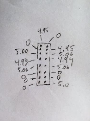
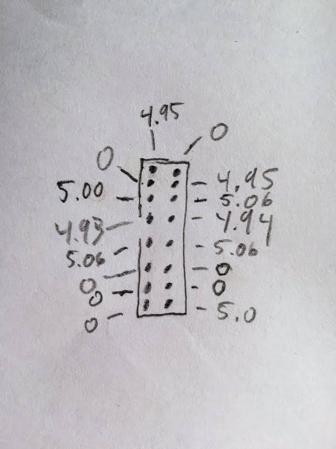
Thanks again Hawkeye. I'll try that. In the meantime, here's the voltages I'm measuring at J15A
-
Could the fact that I haven't yet installed the SD reader contribute to this issue? Does the SD reader need to be installed to see results on the display?
-
Thanks Bruno - for the vid and the suggestions. I am going to try one more LCD and then hit your steps.
Yesterday I gave up. Today I'm willing to try some more

Can I just use isopropyl alcohol as flux remover?
-
One last question.
It was working. Is it possible that it would work (or appear to work) OK with the connection wrong? And then it burnt out? Otherwise this whole thing makes no sense. I never changed the orientation of the connections yet it worked, was legible etc...
-
4 hours ago, Hawkeye said:
+1, it might "just" be a soldering fault somewhere in that area - can you photograph the core front and back (deinstalled STM32F4 module) in high res and post it here?
I already did
 4 hours ago, Hawkeye said:
If you have access to an oscilloscope, you can check all data pins at the display, it should show activity on most lines arriving at the display during startup, interesting are the lines R/S, E and R/W... and if these work properly, check the data lines.
I don't have an oscilloscope. I've tested the pins some.
4 hours ago, Hawkeye said:I assume that you replaced the display "one last time"? Smaller HD44780 test screens are really cheap on ebay, the current one could still be burned from the previous core/wrong polarity?
OK, I'll try another one. Then that's it for now. Maybe in some months I'll get encouraged to go back at it.
4 hours ago, Hawkeye said:Many greets and good luck!
PeterThanks again
-
Here's this just for the record. This was taken at the same time as the above notch/cabling photos.
-
Just now, Hawkeye said:
Hm, a few questions:
* what happens, if you turn the contrast pot? Do the solid blocks visible in the picture just disappear and fade to "nothing"?
Yes. the brightness and contrast work as expected
* which firmware do you have installed? can you install the newest MBSEQ from ucapps (and make sure you use the stm32f4 branch)?
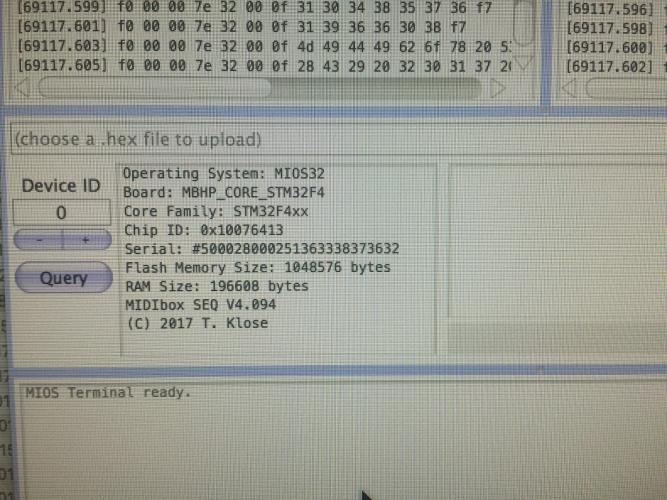
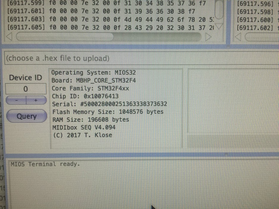
I have midibox_seq_v4_094/MBHP_CORE_STM32F4 installed
* do you "see" the core in MIOS studio and can you send commands to the just installed MBSEQ via the terminal?
Yes, of course. This is all documented in previous posts in this thread (I know.. it's a lot of content ;)
* did you build this second core as a completely new unit, aka have you also installed a new stm32f4 module or have you just plugged the old stm32f4 module to a newly built MIDIbox core?
Ye, completely new as if I had never done it before. New stm32 with a new core.
* if it is a new core, have you checked the orientation and proper installation of the 74hc595 and '541?
Yes, resoldered both of them. Checked the pin orientation many times. Ordered more 595Ns, 541ANs and have a full bag of them now!
Many greets and good luck!
Peter -
Unfortunately, I'm still in the same boat after rearranging things as indicated by TK. See below.
I have to get back to making music soon so I think I am going to have to give up for a while. It is really frustrating that the LCD worked fine for so many weeks and now nothing I do seems to help...

-
Hey TK - thanks!
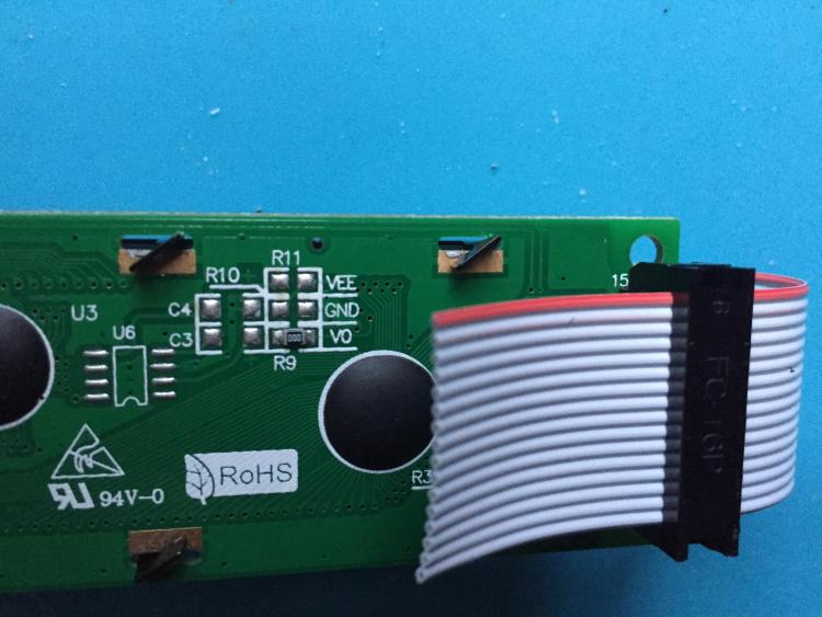
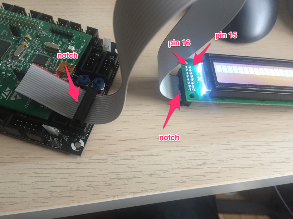
Can you also indicate where the square outlined pin is on the LCD (I assume that the square one is Pin1?) According to your picture I don't have mine arranged correctly however the red stripe IS going to pin 15 on my LCD
-
Mine is hooked up with the red stripe on the arrow to the Core and to pin 15 on the LCD, like so: http://ucapps.de/mbhp/mbhp_lcd_2x20_mios32.pdf
Contrast and brightness work for me.
So that could be your issue - although you say it worked fine before?
-
Same exact thing I'm experiencing. It worked and I put it aside for some weeks while I built the other mods. Now it doesn't and just produces the black bars on the LCD. I've rebuilt my core, ordered another LCD and tried another discovery board - same result. It makes no sense because it worked fine several weeks ago. TK, please help!
What does MIOS Studio say? Does Seq4 actually start?
-
1 hour ago, latigid on said:
Verify each of the intended connection points on J15 are made correctly with the display.
Check for shorts between the cable pins (can happen with misaligned header)
You are fiddling with the contrast and brightness controls each time, right?What firmware is loaded on the Core?
Yes, changing the contrast and brightness often. My assumption is that if you can see the bars then you can see the regular OS display, correct?
-
The only thing I can think of is that I fried all my LCDs somehow. Or else the ribbon cable is just not connected right - even though I've made about 4 of them now!
-
Thanks for the encouragement Peter! I am about to give up :) (for now).
I'm getting a voltage of 4.74 on the LCD pins.
J15_S is set for 5v
I've tried everything. USB mini cables, Micro cables, different 5v wall power supplies. connecting directly to J2, a 5v 1A battery, a 5v 2A USB hub..
-
Just hooked up a new discovery board and still nothing...
New Core, New LCD, New DISC. Wow... no idea what is wrong here...
-
In the meantime I've ordered another DISC board.
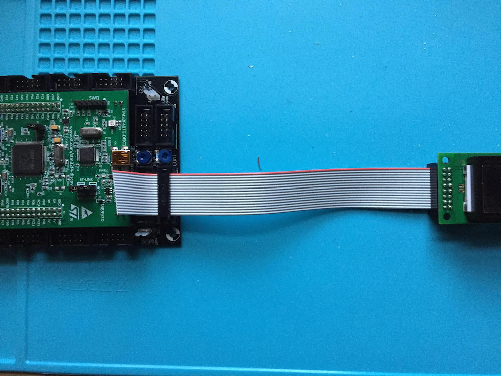
I attached new pics of my Core>LCD cabling. If someone could double check that it is correct that would be great.
Thanks,

-
9 minutes ago, TK. said:
I need some time to thing about how to support this issue remotely...
Best Regards, Thorsten.
It MUST be the discovery board. Everything was working fine and then it sat around for a few weeks. Maybe I put something on it or it got scratched or something. The Disc board is the only thing that hasn't been replaced!
-
Dang. New LCD. New Core. Another $100 in the hole. No progress.... Still getting a bar of rectangles on the LCD. Time for a new Discovery board?

-
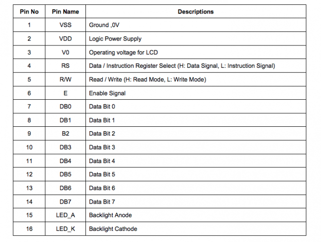
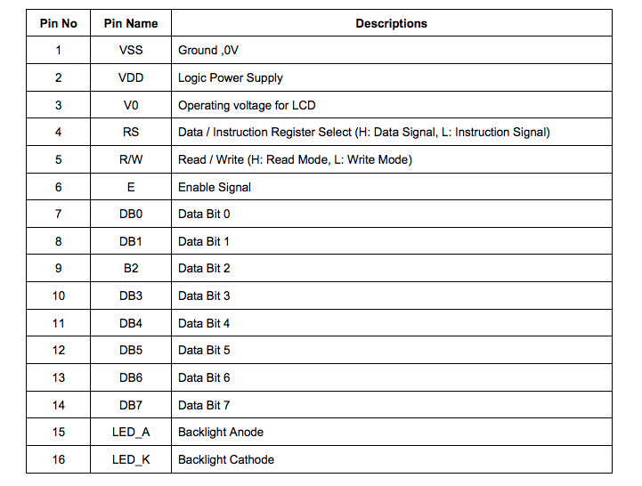
Attached is the data sheet for my LCD but I'm having trouble figuring out how this corresponds to the schematic (http://www.ucapps.de/mbhp/mbhp_core_stm32f4.pdf)
Apologies for my limited knowledge of GPIO but any links or refs you can send my
-
On 10/31/2017 at 4:33 AM, latigid on said:
A common problem with Eurorack power headers is they only work if the notches are polarised the same way on both the bussboard and the module. If the module has "pin 1" on the opposite side as the power output header and both headers are keyed, there is no way to correctly plug in the cable.
The Core schematic is correctly drawn as a "mirrored" header.
Still not quite sure I understand. I have the red stripe going from the inner pin closest to the brightness/contrast pots to pin 15 on the LCD. The LCD has numbered pins.
-
What do you mean 'don't trust the notch on the Core board"?
-
Humph.... Sigh
Just built an entirely new Core board. Same result (sad face). Still getting the same results from the testlcdpin. So that makes me think neither the Core or the LCDs are to blame.
What would you do now? New Discovery Board?
-
that looks awesome! thanks for sharing!
-
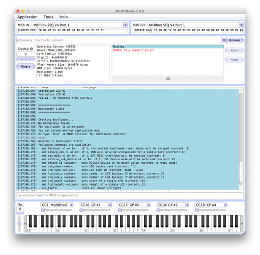
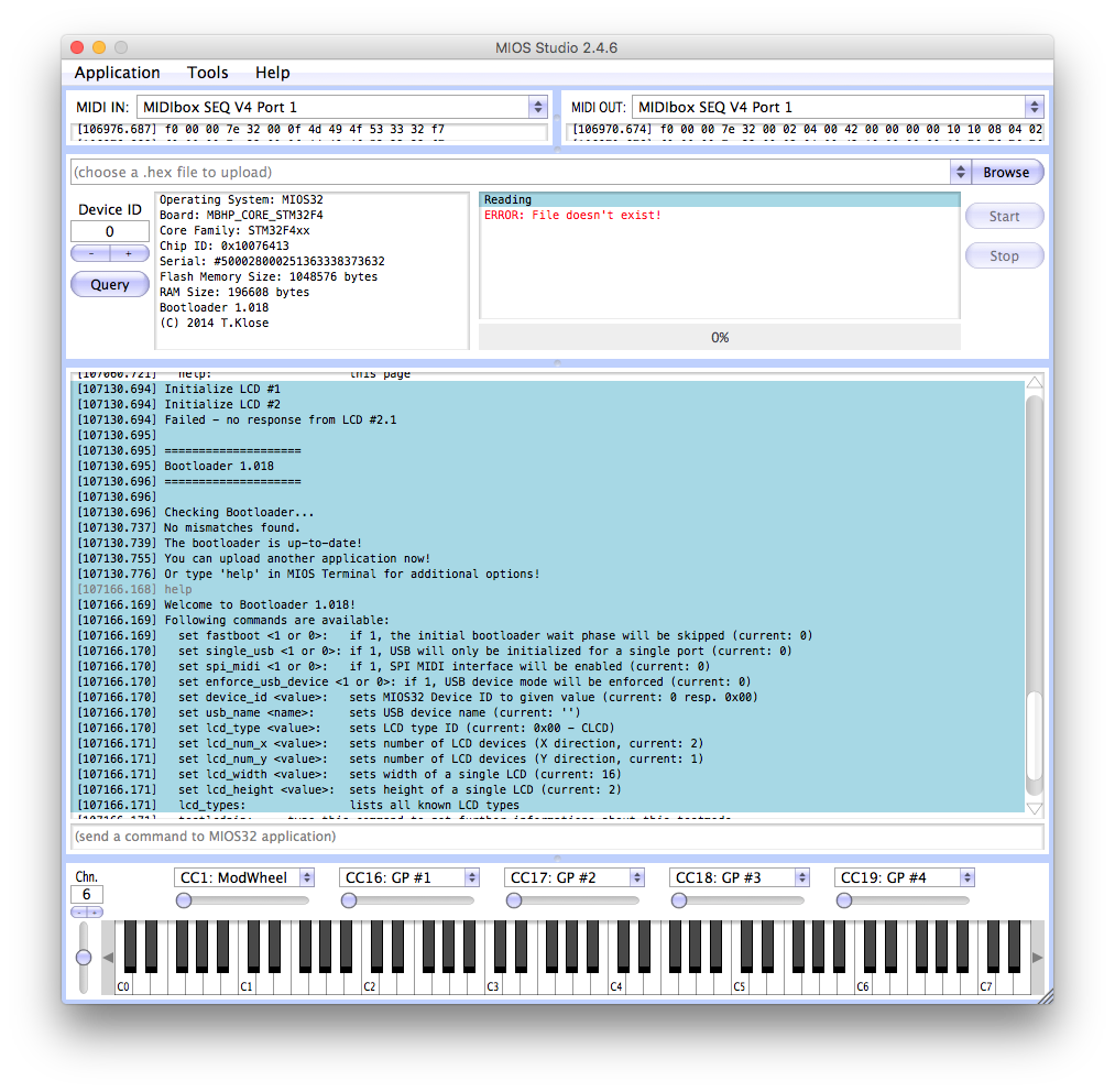
Thanks. This is what I get on the bootloader screen 'help'. Perhaps I did connect the lcd wrongly at some point. Would this really have the potential to damage it?
EDIT : Just noticed that IC1 is getting pretty hot when it's plugged in for 5 minutes or so. I think I'm just going to cough up the $70 and build a new board...
EDIT 2
 Amateur hour. So when I reset IC1 late last night in all my frustration, I put it in backwards....
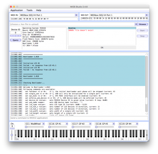
  hence the heat. HOWEVER - when it was reversed, the bootloader recognized LCD 1 and the testlcd pin D1 worked (screenshot 1). Now that IC1 is back facing the correct direction, bootloader says "failed: no response from LCD 1" and testlcdpin 1 doesn't work again. Does this shed any light on the situation? That it recognized the LCD when IP1 is (accidentally) reversed? See screenshot 2.


Displays not initializing after working for a while
in MIDIbox SEQ
Posted