EvilEvilEvil
-
Posts
49 -
Joined
-
Last visited
-
Days Won
1
EvilEvilEvil's Achievements
MIDIbox Newbie (1/4)
1
Reputation
-
Displays not initializing after working for a while
EvilEvilEvil replied to EvilEvilEvil's topic in MIDIbox SEQ
-
Displays not initializing after working for a while
EvilEvilEvil replied to EvilEvilEvil's topic in MIDIbox SEQ
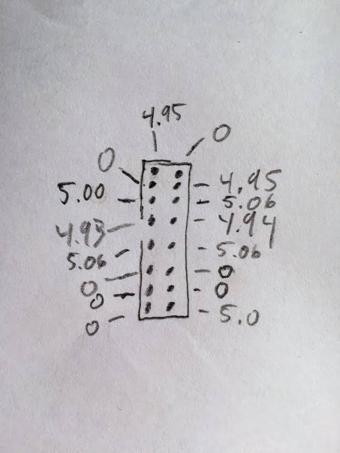
Thanks again Hawkeye. I'll try that. In the meantime, here's the voltages I'm measuring at J15A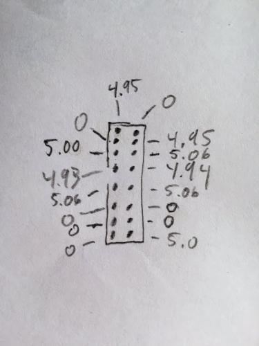
-
Displays not initializing after working for a while
EvilEvilEvil replied to EvilEvilEvil's topic in MIDIbox SEQ
Could the fact that I haven't yet installed the SD reader contribute to this issue? Does the SD reader need to be installed to see results on the display? -
Displays not initializing after working for a while
EvilEvilEvil replied to EvilEvilEvil's topic in MIDIbox SEQ
Thanks Bruno - for the vid and the suggestions. I am going to try one more LCD and then hit your steps. Yesterday I gave up. Today I'm willing to try some more Can I just use isopropyl alcohol as flux remover? -
Displays not initializing after working for a while
EvilEvilEvil replied to EvilEvilEvil's topic in MIDIbox SEQ
One last question. It was working. Is it possible that it would work (or appear to work) OK with the connection wrong? And then it burnt out? Otherwise this whole thing makes no sense. I never changed the orientation of the connections yet it worked, was legible etc... -
Displays not initializing after working for a while
EvilEvilEvil replied to EvilEvilEvil's topic in MIDIbox SEQ
I already did I don't have an oscilloscope. I've tested the pins some. OK, I'll try another one. Then that's it for now. Maybe in some months I'll get encouraged to go back at it. Thanks again -
Displays not initializing after working for a while
EvilEvilEvil replied to EvilEvilEvil's topic in MIDIbox SEQ
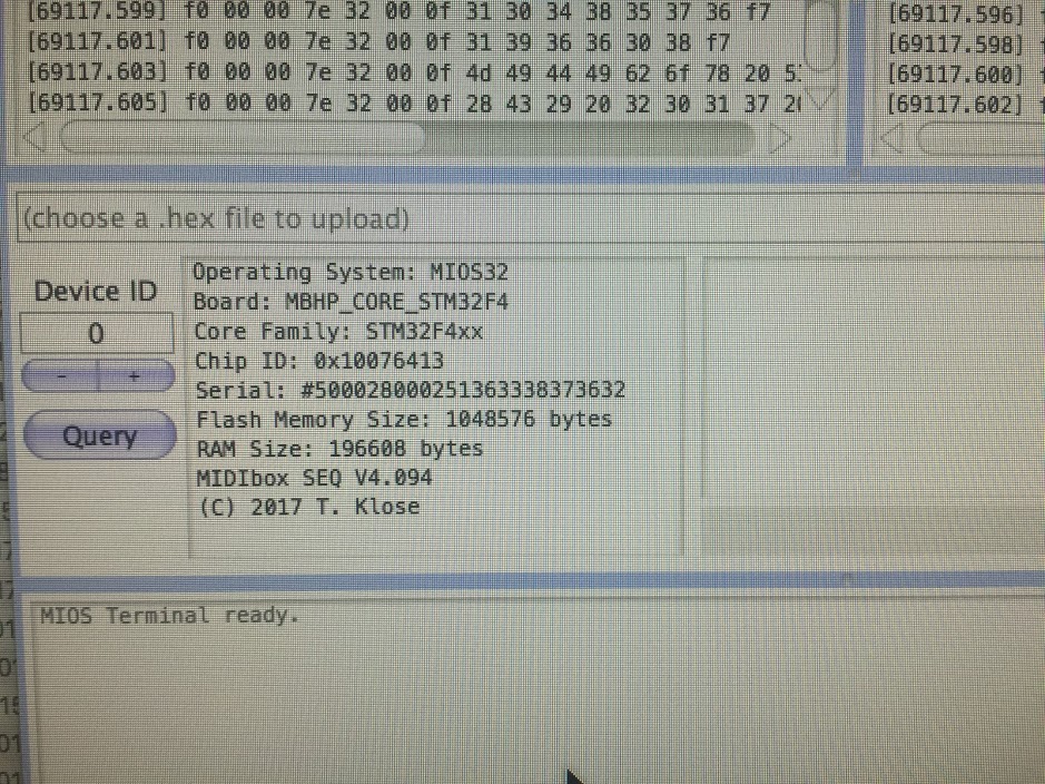
Here's this just for the record. This was taken at the same time as the above notch/cabling photos.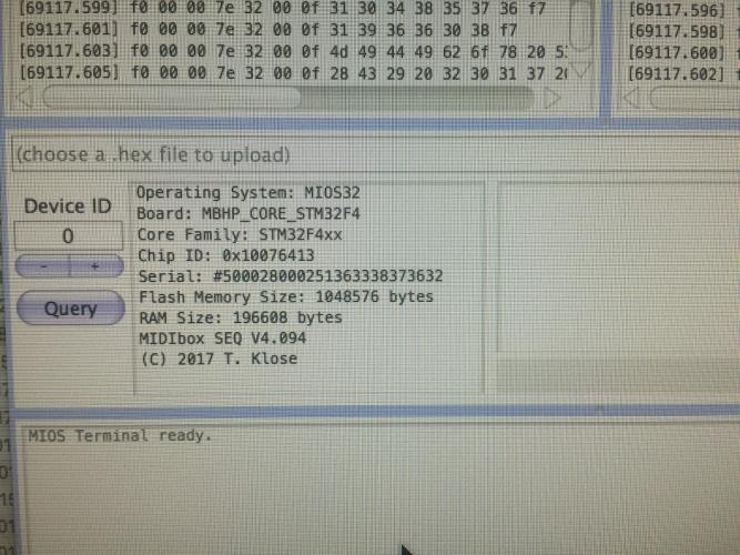
-
Displays not initializing after working for a while
EvilEvilEvil replied to EvilEvilEvil's topic in MIDIbox SEQ
-
Displays not initializing after working for a while
EvilEvilEvil replied to EvilEvilEvil's topic in MIDIbox SEQ
Unfortunately, I'm still in the same boat after rearranging things as indicated by TK. See below. I have to get back to making music soon so I think I am going to have to give up for a while. It is really frustrating that the LCD worked fine for so many weeks and now nothing I do seems to help...
-
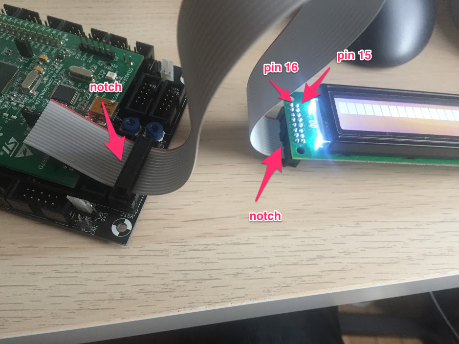
Hey TK - thanks! Can you also indicate where the square outlined pin is on the LCD (I assume that the square one is Pin1?) According to your picture I don't have mine arranged correctly however the red stripe IS going to pin 15 on my LCD
-
Mine is hooked up with the red stripe on the arrow to the Core and to pin 15 on the LCD, like so: http://ucapps.de/mbhp/mbhp_lcd_2x20_mios32.pdf Contrast and brightness work for me. So that could be your issue - although you say it worked fine before?
-
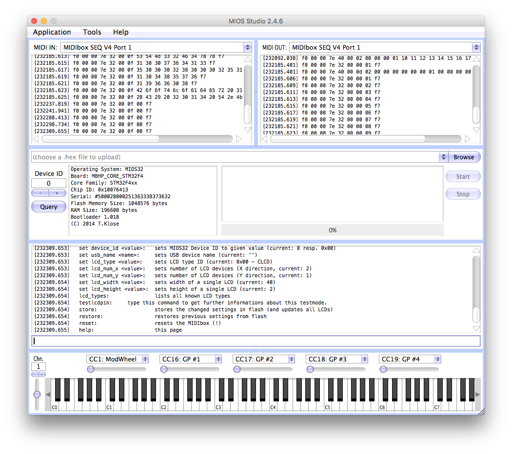
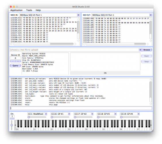
Same exact thing I'm experiencing. It worked and I put it aside for some weeks while I built the other mods. Now it doesn't and just produces the black bars on the LCD. I've rebuilt my core, ordered another LCD and tried another discovery board - same result. It makes no sense because it worked fine several weeks ago. TK, please help! What does MIOS Studio say? Does Seq4 actually start?
-
Displays not initializing after working for a while
EvilEvilEvil replied to EvilEvilEvil's topic in MIDIbox SEQ
Yes, changing the contrast and brightness often. My assumption is that if you can see the bars then you can see the regular OS display, correct? -
Displays not initializing after working for a while
EvilEvilEvil replied to EvilEvilEvil's topic in MIDIbox SEQ
The only thing I can think of is that I fried all my LCDs somehow. Or else the ribbon cable is just not connected right - even though I've made about 4 of them now! -
Displays not initializing after working for a while
EvilEvilEvil replied to EvilEvilEvil's topic in MIDIbox SEQ
Thanks for the encouragement Peter! I am about to give up :) (for now). I'm getting a voltage of 4.74 on the LCD pins. J15_S is set for 5v I've tried everything. USB mini cables, Micro cables, different 5v wall power supplies. connecting directly to J2, a 5v 1A battery, a 5v 2A USB hub..