Manticore
-
Posts
21 -
Joined
-
Last visited
Manticore's Achievements
MIDIbox Newbie (1/4)
0
Reputation
-
yes, I know what you mean; however, only the left of the two decimal points has a LED inside, that's what I meant. The right "point" is only used in the 3733 display.
-
Hi ssp, good luck for your housing; this mostly takes more time than the electronic side of a project. :( Unfortunately the displays do not have two decimal points. It is a HP 3730 type; there is also a version with the dp on the right and they seem to use the same housing for both types. I studied the datasheet AND tried all pins - no dp on the right :( Either I will have to live with this or must get some HP 3733 with dp on the right hand side. We will see... Manticore
-
Oops...my own fault! The displays are with decimal point on the left, not on the right. Would it be possible to modify the software? Manticore
-
Hi, now it works! After assembling another mtc board the fault was exactly present as before. But then after checking the midimon I found the source: it was the socket for the mtc display (sub-d 9 pin male). There was a connection where there should be none... However, one thing remains: as you see on the photo, decimal points are not at the correct position. What is this?! Manticore
-
har har... :D I did notice that, too. Therefore I reduced resolution for the following pics. Sorry for the waste of bandwith :P However, you can at least check EVERY pixel of that LCD ;) To get serious: I think I will put the whole display together once again, but with a bit more accuracy. Maybe this could help... Manticore
-
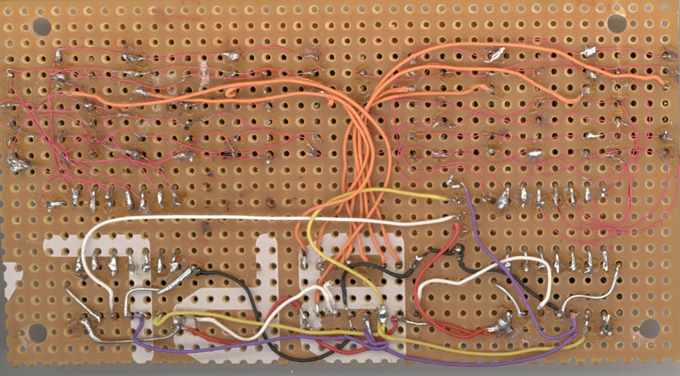
ok...here they are. Maybe the wiring does not look that nice, but as I already said I did check it with the meter. Segment wiring is done with Vero-wire; orange wires are anodes, black is ground, red is +5V, white is SO, yellow is SendClock and violet is ReceiveClock. Connection to the Midimon goes via ribbon cable; this was also checked with meter. Manticore
-
oh...I forgot to mention: when there is no time code displayed on the LCD, on the MTC display all segments are lit with the exception of segment f (the upper left one), including the decimal points. Manticore
-
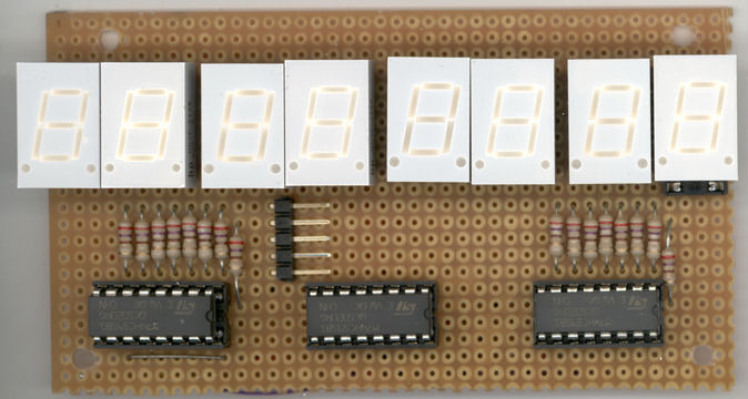
I finally finished the MTC display for the Midimon. However, something's going wrong with it. If you look at the photo you see that the display shows really weird things. Of course I did some tests to find the fault, but no results were found: 1. I triplechecked all connections and possible intercourses with my meter. 2. I exchanged the HC595. 3. I took the HC595s off the sockets, applied +5V to the anode pins and grounded the segment pins to check if all connections are o.k. All the segments were lit as they should. What is also strange is that the displays do not have the same brightness (as seen on the photo; display No. 7 is the brightest one). Even if I exchange them (they are mounted in sockets) the difference in brightness remains. Could this be another software bug in the Midimon app? Manticore IMG_0003.JPG IMG_0003.JPG
-
Unfortunately it took some days before I found the time to check the updated firmware, but now I can say: it works now! Thanx for the supply to stryd_one and of course to Thorsten! Walter a.k.a. Manticore
-
Hi Thorsten, cool...the boss himself is taking care of my problem :D. Thanx a lot; I'll try it tomorrow morning and will post my results. Manticore
-
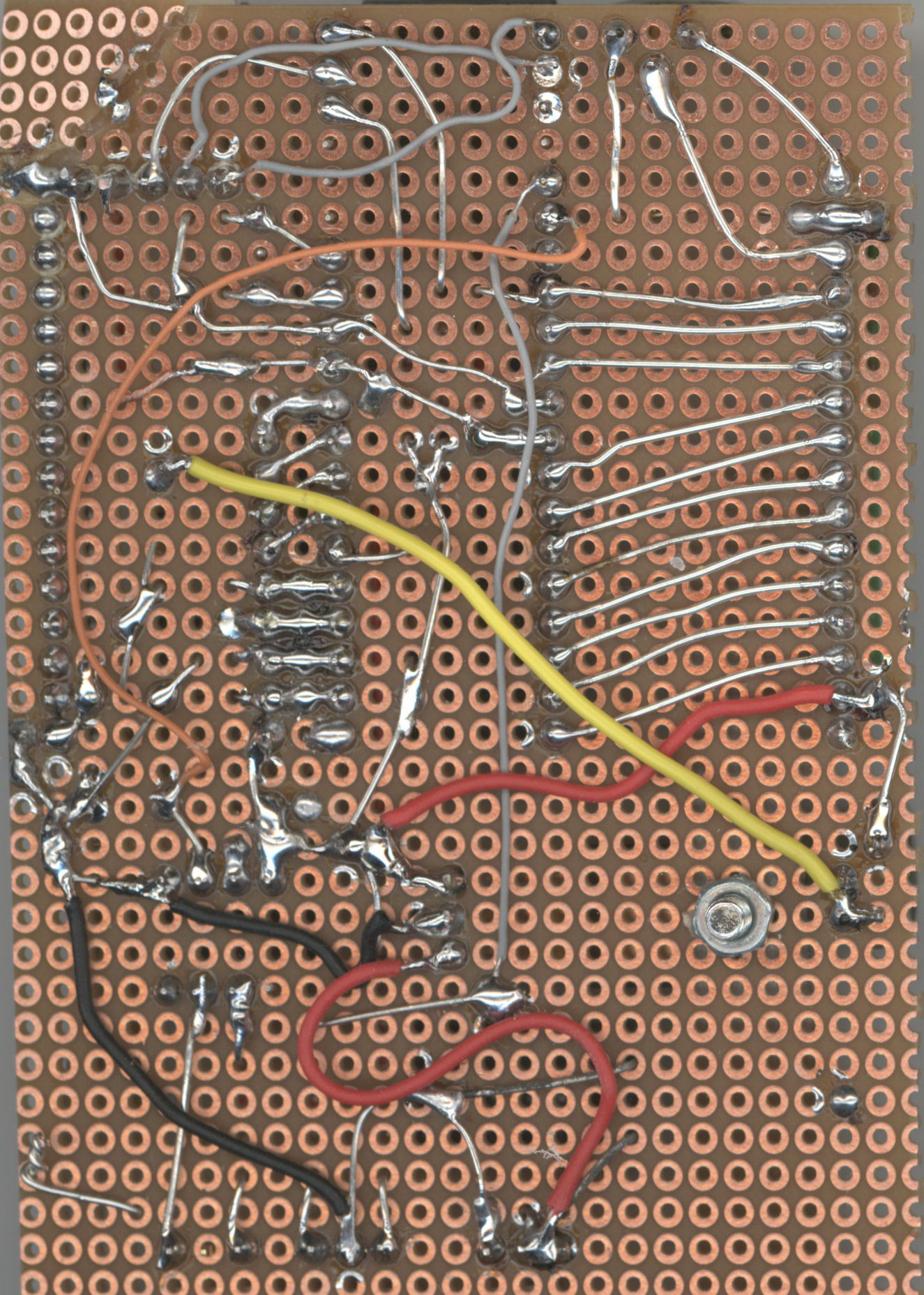
Hmmm... I built a complete Midibox SID that way (at least the control section). By the way, I tested all connections and even possible intersections. The r-net is next to the PIC socket. When you look at the soldering side, pin 1 of the PIC is bottom left. R-Net pins are directly connected to the appropriate pic pins (2,3,4,5,7,8,9,10). In the mean time I tried something else: I put the pic in one of the pcbs of the SIDBox. To make it short: same behaviour even there! RA pins are 0Volt! Next thing I will check is a third PIC - it MUST be a hardware defect!
-
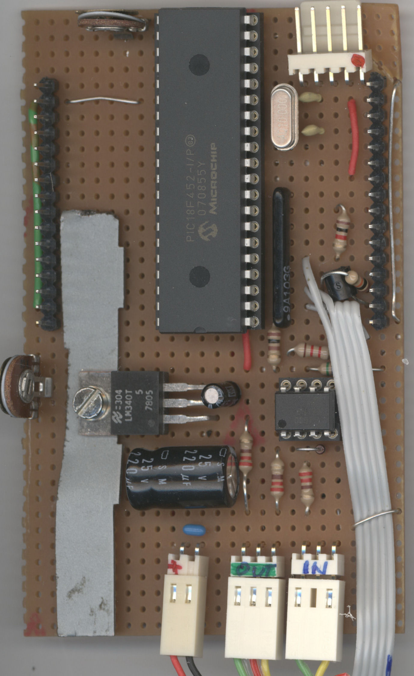
I put the whole d... thing on the flatbed scanner. Some components are hidden underneath the PIC (pull-ups and cap). The display is removed for the foto; it is plugged into the two male 16pin-connectors at the edges. The grey ribbon cable goes to the buttons. Red cables are +, black ones are ground. The yellow one goes to the luminance poti, the orange one connects the opto coupler with the PIC. Grey cables are miscellaneous connections (midi out etc.) Manticore
-
I already did that: on the common pin of the array the 5V are present. 0V at the PIC pins. When I disconnect the resistor array from the pic pins, I measure +5V at the array pins. I did also try to replace the array with simple resistors; no effect. The array seems to be ok. I also replaced the 18f452 (might have been a damaged RA-port), but also no change in the behaviour. It seems that the pins are low by the software?! (I loaded the Midibox application from the ucapps site without any modifications). Very strange.... Manticore
-
Hi everyone, I just put together a core module on breadboard (18f452 based) to use it for the Midimon application. Everything seemed to work fine: I've burned the bootloader to the PIC, then installed MIOS 1.9f and of course the Midimon V 2.0b. MIDI data on the Midi In are diplayed on the LCD. BUT: there is no function with the 4 buttons/switches. They are connected to J5, as shown in the diagram. However, there is no function if I press any of them. What is strange: the pins show nearly 0,0V even if no button is pressed; of course they are pulled up with a 8x10k Resistor array to +5V. Any ideas? Manticore
-
Midibix SID (3 cores / 3 SIDs / Control surface)
Manticore replied to jdelgoulet's topic in MIDIbox SID
Of course not the PSU is noisy or not, but the audio signal might be, due to wiring; that's what I meant. My first MBSID prototype had a PSU with one-way rectification by a single diode (which is absolutely ok for digital stuff); this caused serious 50-hertz-hum on the audio signal. ...BTW, zero noise happens when you short-cut the audio out... ;). Has anyone already thought of including a noise gate inside the MBSID box and maybe have a simple schematic for it? Best regards, Manticore