Manticore
-
Posts
21 -
Joined
-
Last visited
Content Type
Profiles
Forums
Blogs
Gallery
Everything posted by Manticore
-
yes, I know what you mean; however, only the left of the two decimal points has a LED inside, that's what I meant. The right "point" is only used in the 3733 display.
-
Hi ssp, good luck for your housing; this mostly takes more time than the electronic side of a project. :( Unfortunately the displays do not have two decimal points. It is a HP 3730 type; there is also a version with the dp on the right and they seem to use the same housing for both types. I studied the datasheet AND tried all pins - no dp on the right :( Either I will have to live with this or must get some HP 3733 with dp on the right hand side. We will see... Manticore
-
Oops...my own fault! The displays are with decimal point on the left, not on the right. Would it be possible to modify the software? Manticore
-
Hi, now it works! After assembling another mtc board the fault was exactly present as before. But then after checking the midimon I found the source: it was the socket for the mtc display (sub-d 9 pin male). There was a connection where there should be none... However, one thing remains: as you see on the photo, decimal points are not at the correct position. What is this?! Manticore
-
har har... :D I did notice that, too. Therefore I reduced resolution for the following pics. Sorry for the waste of bandwith :P However, you can at least check EVERY pixel of that LCD ;) To get serious: I think I will put the whole display together once again, but with a bit more accuracy. Maybe this could help... Manticore
-
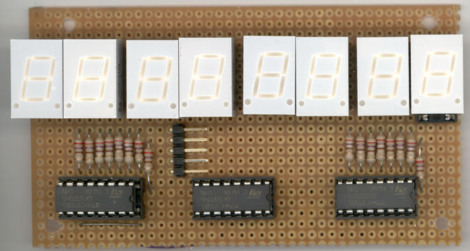
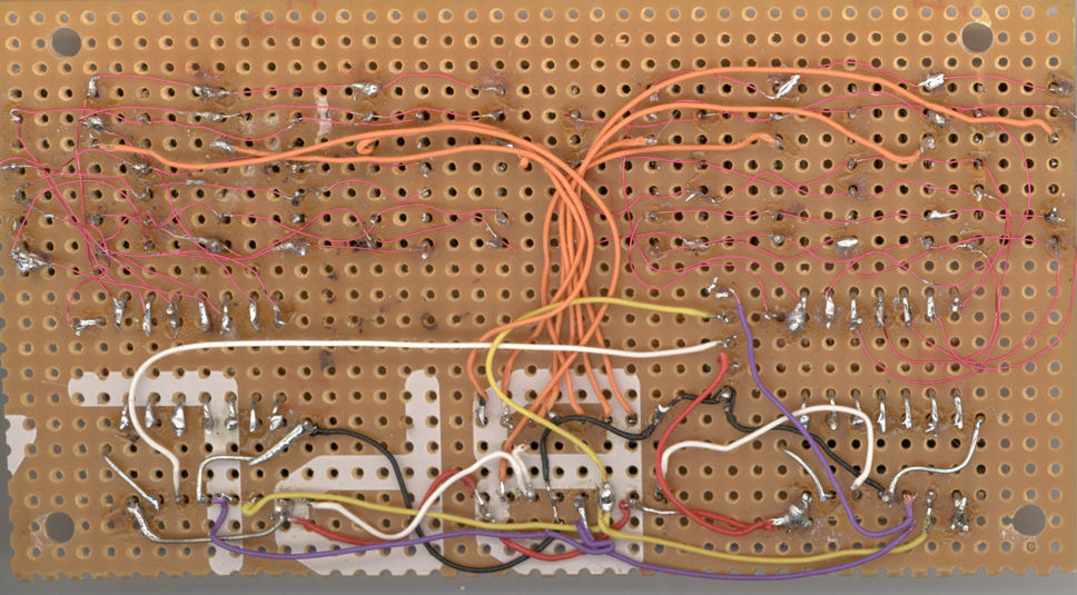
ok...here they are. Maybe the wiring does not look that nice, but as I already said I did check it with the meter. Segment wiring is done with Vero-wire; orange wires are anodes, black is ground, red is +5V, white is SO, yellow is SendClock and violet is ReceiveClock. Connection to the Midimon goes via ribbon cable; this was also checked with meter. Manticore
-
oh...I forgot to mention: when there is no time code displayed on the LCD, on the MTC display all segments are lit with the exception of segment f (the upper left one), including the decimal points. Manticore
-
I finally finished the MTC display for the Midimon. However, something's going wrong with it. If you look at the photo you see that the display shows really weird things. Of course I did some tests to find the fault, but no results were found: 1. I triplechecked all connections and possible intercourses with my meter. 2. I exchanged the HC595. 3. I took the HC595s off the sockets, applied +5V to the anode pins and grounded the segment pins to check if all connections are o.k. All the segments were lit as they should. What is also strange is that the displays do not have the same brightness (as seen on the photo; display No. 7 is the brightest one). Even if I exchange them (they are mounted in sockets) the difference in brightness remains. Could this be another software bug in the Midimon app? Manticore IMG_0003.JPG IMG_0003.JPG
-
Unfortunately it took some days before I found the time to check the updated firmware, but now I can say: it works now! Thanx for the supply to stryd_one and of course to Thorsten! Walter a.k.a. Manticore
-
Hi Thorsten, cool...the boss himself is taking care of my problem :D. Thanx a lot; I'll try it tomorrow morning and will post my results. Manticore
-
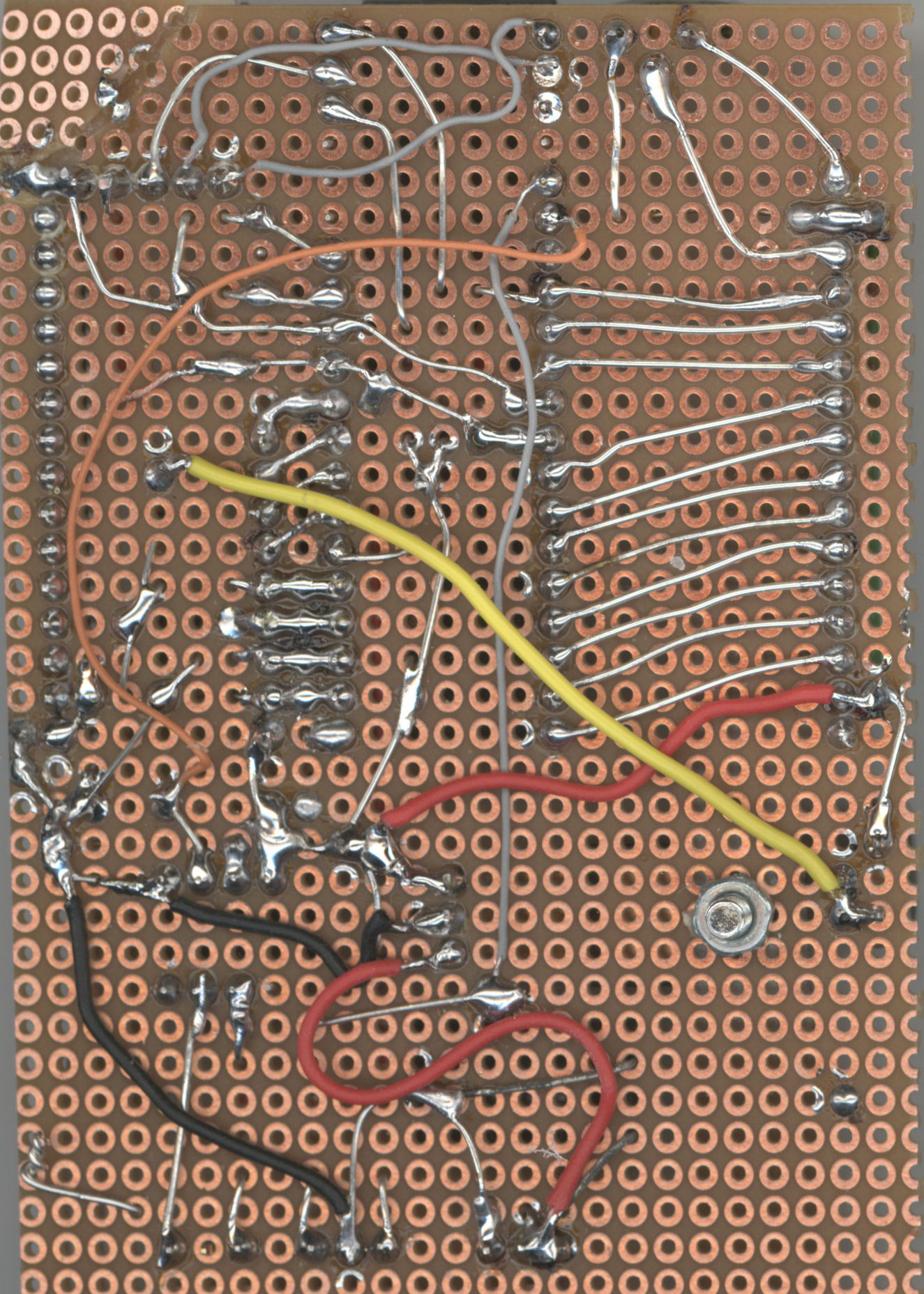
Hmmm... I built a complete Midibox SID that way (at least the control section). By the way, I tested all connections and even possible intersections. The r-net is next to the PIC socket. When you look at the soldering side, pin 1 of the PIC is bottom left. R-Net pins are directly connected to the appropriate pic pins (2,3,4,5,7,8,9,10). In the mean time I tried something else: I put the pic in one of the pcbs of the SIDBox. To make it short: same behaviour even there! RA pins are 0Volt! Next thing I will check is a third PIC - it MUST be a hardware defect!
-
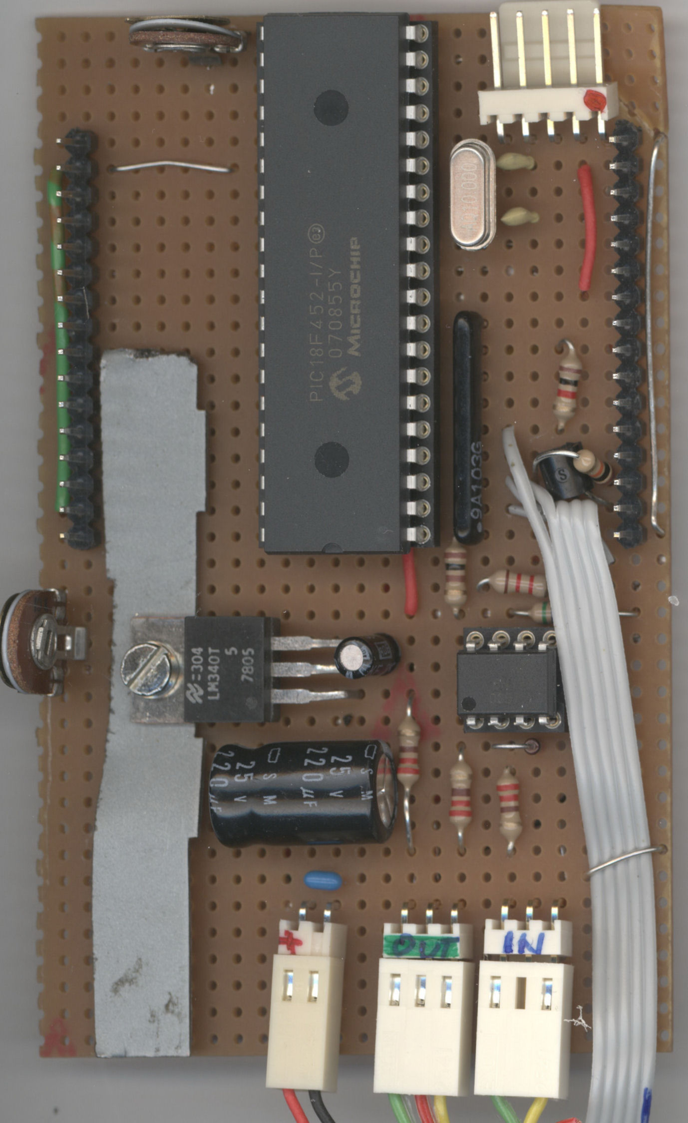
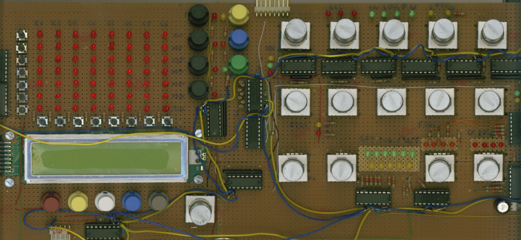
I put the whole d... thing on the flatbed scanner. Some components are hidden underneath the PIC (pull-ups and cap). The display is removed for the foto; it is plugged into the two male 16pin-connectors at the edges. The grey ribbon cable goes to the buttons. Red cables are +, black ones are ground. The yellow one goes to the luminance poti, the orange one connects the opto coupler with the PIC. Grey cables are miscellaneous connections (midi out etc.) Manticore
-
I already did that: on the common pin of the array the 5V are present. 0V at the PIC pins. When I disconnect the resistor array from the pic pins, I measure +5V at the array pins. I did also try to replace the array with simple resistors; no effect. The array seems to be ok. I also replaced the 18f452 (might have been a damaged RA-port), but also no change in the behaviour. It seems that the pins are low by the software?! (I loaded the Midibox application from the ucapps site without any modifications). Very strange.... Manticore
-
Hi everyone, I just put together a core module on breadboard (18f452 based) to use it for the Midimon application. Everything seemed to work fine: I've burned the bootloader to the PIC, then installed MIOS 1.9f and of course the Midimon V 2.0b. MIDI data on the Midi In are diplayed on the LCD. BUT: there is no function with the 4 buttons/switches. They are connected to J5, as shown in the diagram. However, there is no function if I press any of them. What is strange: the pins show nearly 0,0V even if no button is pressed; of course they are pulled up with a 8x10k Resistor array to +5V. Any ideas? Manticore
-
Midibix SID (3 cores / 3 SIDs / Control surface)
Manticore replied to jdelgoulet's topic in MIDIbox SID
Of course not the PSU is noisy or not, but the audio signal might be, due to wiring; that's what I meant. My first MBSID prototype had a PSU with one-way rectification by a single diode (which is absolutely ok for digital stuff); this caused serious 50-hertz-hum on the audio signal. ...BTW, zero noise happens when you short-cut the audio out... ;). Has anyone already thought of including a noise gate inside the MBSID box and maybe have a simple schematic for it? Best regards, Manticore -
Midibix SID (3 cores / 3 SIDs / Control surface)
Manticore replied to jdelgoulet's topic in MIDIbox SID
Since I do not have a C64 PSU, I built a custom PSU. It consists of a transformer with separate coils (this is important to avoid ground loops); mine was from Pollin and has an 8V/1,7A coil, a 12-0-12V/0,8A and 4V coil (which is not used yet). Of course you could take two separate transformers; this is a matter of available space. I made a 5V stabilized output, which serves the cores except the master core; this is supplied by unstabilized 10V and a voltage regulator on the master (this is for the display illumination; ). I also stuffed a -12V regulator in the PSU to have a balanced (symmetrical) supply for op-amps (maybe I will build an audio mixer later). The regulators are attached to a heat sink; this will not get too hot. All voltage grounds are connected in the PSU, so you must take care to not connect the a second time. On the boards the input capacitors (1000uF) are stuffed; rectifier and regulators are replaced by appropiate bridges (except on the master, see above). There is absolutely no hum and no hiss on the audio outputs. Best regards, Manticore -
Probably it would not have been that "easy" without this forum! Of course, there WERE some difficulties in getting all the stuff together; especially because I did not use PCBs for the DINs and DOUTs (to get the wiring of the buttons, leds and encoders more compact). But after all, this was no big problem due to all the information provided here. But anyhow, it will soon be finished - and some day it will be upgraded to V2, of course! Next project is already waiting - to get an at least 25 years old CASIO keyboard midified (to use it as a mobile master keyboard). I know it is offtopic here, but are there already solutions (read a matrix keyboard; so far I've just found how to connect a C64 keyboard to MB)? Best regards, Manticore
-
Now it works! I simply forgot to connect the PWM pin of J10 to pin 17 of the PIC on all the slaves! How stupid can one be... Thanks for your hints, though! Best regards, Manticore
-
It is MIOS 1.9e and SID 1.7303b (since I do not own 18F4685 yet). MIOS Studio is 7.4 Beta. I will try the hardware tests tomorrow (needs some soldering, since I did not stuff the unnecessarily pins and sockets on the boards). For now, thanks for your tips.
-
No, the optocouplers are not stuffed on the slaves (testing of the pics was done on the master), and yes, the connection is via tx/rx, not over MIDI IN/OUT. The wiring follows the optimized... thing, at least, as far as the Non-power connections are concerned (I've made a custom power supply using a transformer with 8V/12-0-12V/15V by POLLIN; it delivers +5V stab. for the slave cores/SID, 10V unstab. for the Master core and 12V stab. for the SID; a -12V stab. is for further expansions. All voltages have a common ground connection in the power supply). A bit confused...
-
Hello world ;-) as this is my first posting here - although I'm reading the forum for quite a while - I will briefly introduce myself. I am from Germany, involved in electronics (as a hobbyist!) since about fourty years (yes, I'm that old, man!), and also in acoustic and electronic music since that time. My first MB project was a MIDI Merger, then a MIDIbox 64, and now my current project is a SIDx4 V1 with Control Unit Step C. The SID is almost ready (except the front panel), but now I have a strange behaviour: it seems, that the MIDI link has no effect. What I have done so far: - all the cores are stuffed with MIOS and the appropriate SID application; the IDs are 0, 1, 2, 3 - the slave cores are checked and working - the wiring of the modules SEEMS to be ok (MIDI out from Master to MIDI ins on Slaves) - when the LINK button is pressed, the LINK LED lights, BUT: when MIOS studio is running, it shows a Program Change 0 on Channel 1, when LINK is pressed! Is that ok? - no sound comes from the slaves, but only from the Master - in the CFG menu, the DEVICE value cannot be changed (it reads "--") Have I missed something? I read all the WIKI and all the tutorials, but nothing found so far. Maybe it is a hardware issue? Sorry for the long post! I've attached a pic of my panel, so if you are interested... Manticore