Shaeded
-
Posts
13 -
Joined
-
Last visited
Shaeded's Achievements
MIDIbox Newbie (1/4)
0
Reputation
-
HEY Did it. Problem solved!! :hyper: Goddam ribbon cable :mad:. code just got simpler! RESET_HW EVENT_LED_MATRIX id=1 type=NoteOn key=36 DOUT_MATRIX n=1 rows=4 sr_dout_sel1=0 sr_dout_r1=2 sr_dout_r2=3 [/xml] Each LED in the Matrix is triggered by a separate note, thats what i was looking for! Cheers
-
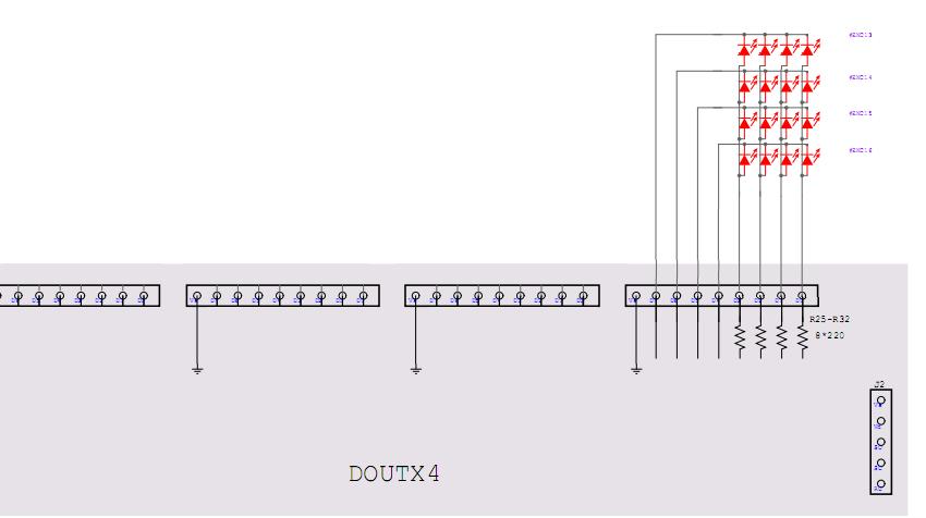
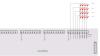
Ok Ive managed to get notes from the buttons on the DIN (solved). The LED's are also scanning! but the marked LED's are causing problems. They are being scanned, but some are already lit when i load the .NGC file (should be off, like the other LED's). I need some assistance on this issue. :sad: Here is my test code: # Reset to default RESET_HW EVENT_LED_MATRIX id=1 hw_id=1 colour=1 dimmed=1 type=NoteOn key=36 chn=1 DOUT_MATRIX n=1 rows=4 inverted=0 sr_dout_sel1=1 sr_dout_r1=2 sr_dout_g1=3 DOUT_MATRIX n=2 rows=4 inverted=0 sr_dout_sel1=2 sr_dout_r1=5 sr_dout_g1=6[/xml] My circuit, see attachment THX :rolleyes:
-
Hi Thanks for the reply. ive added a SD-Card the thing is working now. Im just gonna try to figure out the coding, the next few days. If i get stuck, ill post Cheers
-
Ok I soldered a SD-card to the LPC17. I am now able to access the config files. I think the DEFAULT.NGC + DEFAULT.MIO are the ones i need to be modify. Is this correct?
-
Hello Ive programmed the PIC based core in the past, to me programming was straight foward (Text edit etc....). This new core LPC17 is causing me headaches. Ive sucsessfully uploaded programms (MIDIO128 V3 or MIDIbox NG) and they worked partially (due to my hardware layout, i didnt expect them to work perfectly). the MIDIO128 V3 software worked better, because i have a AINSER8 with 8 pots, an the pots work. My problem is the Matrix im running its not working properly see image. I think i figured out the problem, its not scanning/running in matrix mode. So in order to get everything running i need to modify the code. I cant figure a couple of things out. So my qustions: 1. With my layout (8pots + matrix image). witch programm would be the better to start with: MIDIO128 V3 or MIDIbox NG 2. Where are the Config files 3. Do i need a SD-card to get access to the config files? 4. Whats the best way to modify the code (MIOS Studio....) THX
-
Hi Thanks for the feedback. I came up with this solution (PCB2), this should work right?
-
Ok I think i overlooked something. The LPC17 is limited to 8 AIN's in the design layout. knowing this it should be capable of running 8x 4051. Am i correct? I want to hook up 20 pots to the LPC17 and already have the PCB with 20 pots and 3x 4051 soldered, so the AINSER64 in not a option :no:. Will this work? THX
-
Hello Community I wanted to know why the documentation of the LPC17 Core & AIN states: "For MIOS32 based applications, e.g. running on a MBHP_CORE_LPC17 module, please use MBHP_AINSER64!". Why? Is it a supply voltage issue? Will a AINX4 work on a LPC17? I want to scan a AINX4, but want to use the LPC17 for future upgrades. THX
-
Hi Everyone I wanted to know if the attached 4x4 LED matrix wiring schematic would work. I know i would have to Rewrite some code and stuff. Or will i have to stick with the traditional LED matrix wiring (http://www.ucapps.de...x4_ledrings.pdf) and use 2x 74HC595. Im trying to reduce part's count on my new project. Thanx for the Help :D
-
Yeeeeaaaaahhhhh Your a good man Gioxannes, things are working fine now. Now with your code, it seems that my SR9 on J? wont be sending out any midi messages/notes (its ok, im not using it). Im just trying to figure out, what the changes to the code meant (i think i understood :)) Once again GOOD MAN! Thanx
-
OK in short: Buttons are connected to J4 OK in long: J3 4xButtons, J5 1xEncoder 2xButtons, J6 4xButtons, J7 1xEncoder 2xButtons, J8 1xEncoder, J9 2xButtons, J10 4xButtons (all working) I swapped the SR (74HC165) 1 and 3. Everything on the 3rd SR still worked. Everything on the 1st SR J3 4xbuttons, still worked. J4 4xButtons no function. That Ellimnates the possabilitie of a fried Chip. ??? I'll take a look at the DINX4 board, but i doubt thats the problem. Then again you never know. Im not at home right now, so i cant send you my .asm now.
-
Hi Thanks for the advice, i already knew that. I used it a 1000 times. But now im looking forward, to stepping up my game. Take a look at my status, im a Newbie. Im not planning on staying a newbie. I have a little to none programming skills :P. But! Im probably the best Electronics Technician out there :o(OMG)(LOL) ;). NO! Im just very GOOD. ;). So my status is an issue here. Why cant my Status be: Midibox Electronics Guru with no programming skills :P (that would be a long tile) No! OK, i know you have to earn your stripes. :D I want to edit the *.asm/*.inc manualy, so i dont have to use the MB64E editor (No offence the Tool is great). I've already edited the setup_midibox16e.asm to suit my needs. I just cant figure out what part of the *.asm/*.inc i need to edit to get J4 on the DINX4 up an running. A little code/pointing out where to look, whould be of help.
-
Hi Im using the MB64E application, my setup consits of 1xAINX3, 1xDINX4, 1xCORE V3 (No LCD!). Pots, Enc's, Buttons. AINX3 no problem. DINX4 J3, J5-J10(Buttons, Enc's) no problem. DINX4 J4 not reacting to pressed buttons. Now i know that J4 in the standard MB64E firmware is maped to the F1,F2,F3,F4. I need a little help on Editing the setup_midibox16e.asm. I want the Buttons on J4 to output notes Thanx