juhnumoffa
-
Posts
3 -
Joined
-
Last visited
juhnumoffa's Achievements
MIDIbox Newbie (1/4)
0
Reputation
-
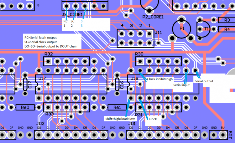
Ok, figured out the issue, seem to have a working MB-6582 now! The trace from following J9_core1 pads going to the HC595 and HC165 were cut: - SC (pin 2 from left) - SI (pin 3 from left) Fixed it by scraping the laquer off and bridged it with solder to the pad. --- Took a while to find as it required some reading into how the DIN and DOUT modules work, process was about the following: - Inserted PIC1 into slot of core1 and changed the ID, flashed the MB6582 program and the PIC behaved the same. This eliminated possibility of faulty PIC -Diodes lit up fully with the LED tester, so I assumed the connections to the 595HC were good. Started testing this with the SRIO_interconnect program. I was puzzled because voltages at J8_CORE1 and J9_CORE1 looked to be ok. -Looking through the PCB layout drawing and datasheets of HC165/HC595, put back in the MB6582 software and started measuring voltages at the HC595 and HC165 pins. At the pins of HC165 I noticed that the SC line was practically constant around 5V with some 100mV noise from the other serial lines (RC...). Attached also my crude picture indicating which signals should be where. ------- Other issues I have had were also on the base PCB - Two transistors had a via where there was not contact on both sides to the trace. Fixed this by soldering the transistor leg from both sides to the pad.
-
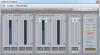
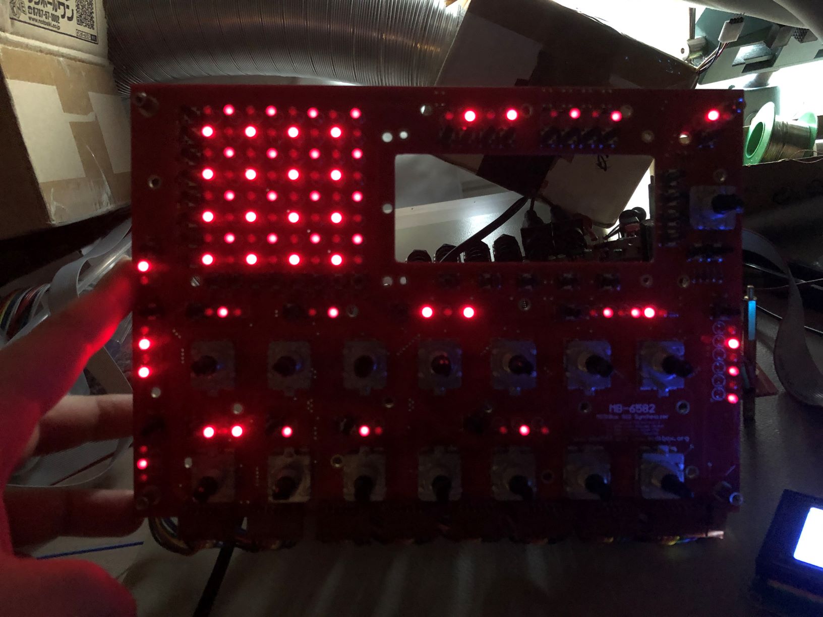
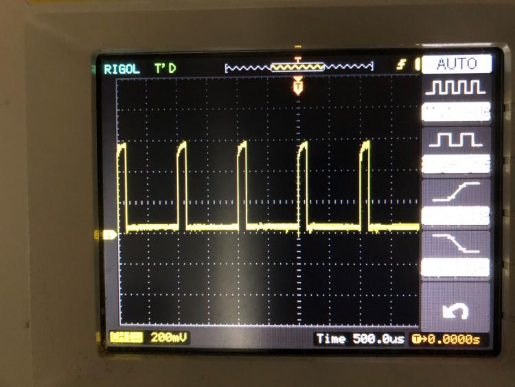
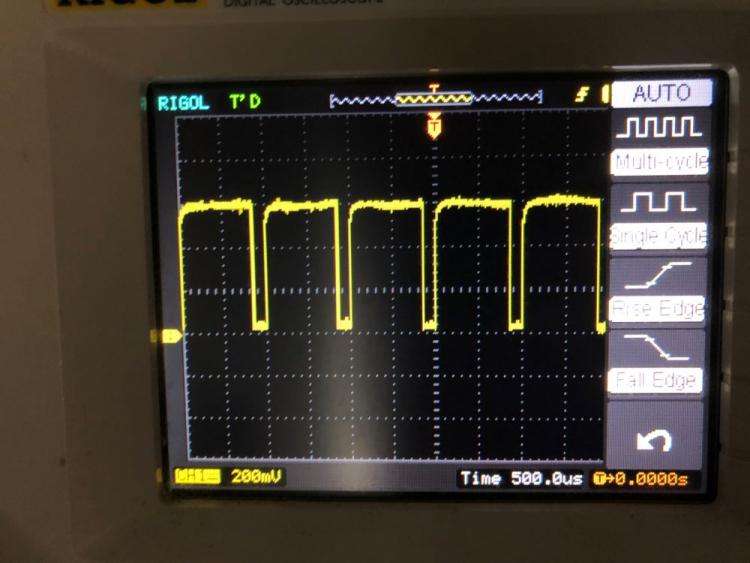
Hi, My almost complete MB-6582 (feedback pots missing) is having a strange issue where all LEDs light up in checkerboard pattern, no buttons or encoders respond. Control surface is ok, I tested it according to the instructions here: http://www.midibox.org/dokuwiki/doku.php?id=control_surface_troubleshooting The HC165 (which I understand manage the buttons and encoders) have ~4.84V at the 5V pin: http://midibox.org/forums/topic/21318-quick-n-dirty-voltage-test-chart-for-mb-6582-base-pcb/#comment-186193 The PIC was updated with MIOS studio from 1.9f to 1.9h, after which I installed setup_mb6582.hex from midibox_sid_v2_044. I have attached some photos also of oscilloscope capture of the signal that turns on every other LED. It seems the wider pulse is turning the LEDs on, but the off LEDs also see a short pulse. The LCD shows the text: E002 | PInt Ld Chn. 1 1---|Lead Patch Any ideas what could be wrong? I am beginning to think it could be an issue with the PIC.

-
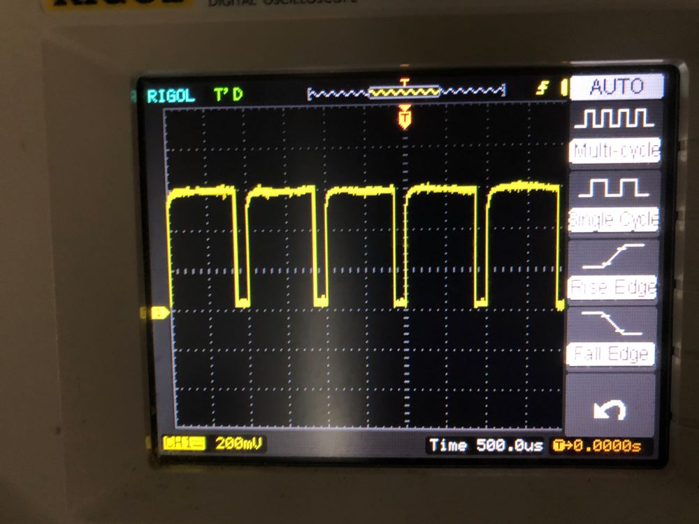
Hi, I was wondering if my sammichFM is quiet. When I am using four instruments, I get in around 70% of maximum peak volume to my soundcard. The volumes are set in the user menu to 127, I am using the default patch instruments.