FoneBone
-
Posts
45 -
Joined
-
Last visited
Never
Content Type
Profiles
Forums
Blogs
Gallery
Everything posted by FoneBone
-
jup.... that works.... when I push the preset buttons of my POD it shows for 1A = Patch2, 1B = Patch 3.... changing the amp type or effect doesn't shows up anything.
-
I've tried, but nothing happens :( Next time I will connect the amp to MIDIOx and test the MIDI INPUT while pressing TAP and A,B,C, or D? Maybe this will be more helpful. I guess the normal preset change didn't send any MIDI data. We will see.
-
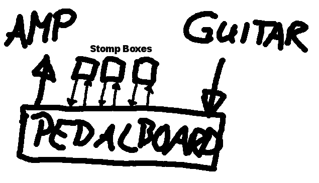
Yep... "PC updating BS 0/1" AMD Athlon 64 X2 5200+, ASRock MB, 2GB RAM, LogiLink USB MIDI Interface, Win XP Pro I have tried it, but Pedal Box Editor crashes always, after pushing Send button. TIMESTAMP IN PORT STATUS DATA1 DATA2 CHAN NOTE EVENT 00011CDD 9 -- B0 0C 05 1 --- Control Change 00011CDD 9 -- B0 0D 28 1 --- Control Change 00011CDF 9 -- B0 0E 32 1 --- Control Change 00011CE0 9 -- B0 0F 74 1 --- Control Change 00011CE1 9 -- B0 10 48 1 --- Control Change 00011CE2 9 -- B0 15 00 1 --- CC: 21 (E-MU) 00011CE3 9 -- B0 11 68 1 --- Control Change 00011CE4 9 -- B0 18 50 1 --- CC: 24 (E-MU) 00011CE5 9 -- B0 17 66 1 --- CC: 23 (E-MU) 00011CE6 9 -- B0 49 7F 1 --- CC: Attack Time 00011CE7 9 -- B0 19 00 1 --- Control Change 00011CE8 9 -- B0 1A 7F 1 --- Control Change 00011CE9 9 -- B0 1B 7F 1 --- Control Change 00011CEA 9 -- B0 25 7F 1 --- Control Change 00011CEB 9 -- B0 26 20 1 --- CC: Data Entry LSB 00011CEC 9 -- B0 27 2E 1 --- Control Change 00011CEE 9 -- B0 28 40 1 --- Control Change 00011CEE 9 -- B0 29 5C 1 --- Control Change 00011CF0 9 -- B0 2E 00 1 --- Control Change 00011CF1 9 -- B0 2F 00 1 --- Control Change 00011CF2 9 -- B0 2D 7F 1 --- Control Change 00011CF3 9 -- B0 2C 00 1 --- Control Change 00011CF4 9 -- B0 47 01 1 --- CC: Harmonic Content That's what MIDIOx shows in the MIDI IN window, after changing one amp to another (in POD2.0). I haven't my HD147 at home, so I have to try this later. But I was wrong. When I change the bank (ex. 1A to 1B) it only shows: 00059DCA 9 -- C0 02 -- 1 --- PC: Elec Grand Piano As I understand your schematic of switching stomp boxes on and off by the relays, you have to go into the electronics of the stomp boxes, or am I wrong?True Bypass would mean, your stomp boxes are always ON. You would just use a switch to bypass them, like a MIDI Switcher / Looper would do. Take a look at the first picture. There are 3 switches in the middle. When they are OFF, the guitar signal would go thru, without passing any (or maybe much less electronics). The idea is, to controll these switches via MIDI in your pedal board. So you need some send and return jacks, and one in and output jack for the guitar (pic2).
-
Successfully updated to version 2 beta 2.... but for an unknown reason I'm still not able to upload bankstick files via the editor (when use feedback from core is selected). When I deselect it, the blocks were send, but in the end the core don't reset. When I reconnect pedal board after this update the new bankstick file was'nt updated... My only solution is the use of sysexbox for the upload... don't know why. To the other problem: I've found in my manual and... but this is MIDI SysEX.... I really don't know, if this will be helpful, but I know that the original FBV (Floorboard of Line6) recieves this settings. Btw. Yesterday I've connected my POD2.0 via MIDI to my PC. By pushing the bank buttons, the MIDI IN window of MIDIOx recieved some (more than one) messages. I guess my HD147 will do the same ;D And one last thing: Cool updated connection schematics on the wiki. The only thing I don't understand is, how to connect stompboxes. Wouldn't it be easier (without hard wiring) to implement some kind of true bypass circuit? At this point I only have to say thank you.... ;)
-
no problem... just downgraded to v2b1b for the moment ;D EDIT: Today I was in my rehearsal room to test the pedal board. Works great, but is it possible, that pedal board will recieve the status of the effects (modulation and delay) used in every preset (bank)? Example: When I use a preset, which contains a digital delay and a phaser (both are build-in effects of the amp) and I wanted to switch them off, I have to step two times (first on, then off). Would be great, if pedal board could recognize this status by switching between the presets.
-
Hi, I've updated to PedalBoard v2b2. And I've tried to update my banksticks, but I got a "Version ID Mismatch" for bankstick 1. ..."Have 101 Need 21"... Result is: "Error 241" Regards FoneBone
-
Would it be possible to edit bank-names directly on pedal-board, without pre-naming them before installing? Maybe in future versions of pedalbox/-board?
-
SUCCESS.... I have to change all options to "Toggle".... then LEDs are working and on/off of the fixed buttons is working, too. Thanks a lot. More to come, when housing is finished ;D EDIT: 2 pics with LEDs..... btw: display bug of up and down button is gone!!! IMG_0926 (Large).JPG IMG_0927 (Large).JPG
-
Hi, I've attached it, just delete the .zip-suffix. I meant indicator LEDs for the Up- and Down-Buttons, just for the pressed-status they light up. Back to the other LED-problem:Do I have to but unused SR's to Ground, like I did for DIN-modul? MyPedalBoard.pbx.zip
-
I've now tested your setting for the SR's... LEDs don't work. ??? Then I've tested the dout_buttons as you told... LEDs work. ;D All buttons send MIDI, banked and fixed ones. Buttons are mapped as follows: Button DIN DOUT Fixed1 J4 D0 J3 D7 Fixed2 J4 D1 J3 D6 Fixed3 J4 D2 J3 D5 Fixed4 J4 D3 J3 D4 Fixed5 J3 D4 J3 D3 Fixed6 J3 D5 J3 D2 Bank1 J3 D6 J3 D1 Bank2 J3 D7 J3 D0 Bank3 J6 D0 J4 D7 Bank4 J6 D1 J4 D6 UP J6 D2 DOWN J6 D3 Btw: Is it possible to set LEDs for BANK UP and BANK DOWN? Which pbx file do you want? master bs or device bs?
-
Here are the first pics of my Pedal Board. The "case" is just a prototype (box of my mainboard) and will be replaced with an aluminuim-case when all is done. Next thing to do is installing the LEDs. Some bugs: - bank changing displays wrong infos (bug as known in the wiki) - my 5 buttons (COMP, MOD, DELAY, REVERB, FX LOOP) are fixed ones and should switch between "on" and "off", but they always stay "off". Little info: All buttons are momentary switches. EDIT: The indicator LEDs don't work and I have no idea why... ??? Here is my pbx_config.h /* * MIOS Pedal Box / Pedal Board - pbx_config.h * v2beta1b - February 2008 * ========================================================================== * * Copyright (C) 2008 Mick Crozier mcrozier@iinet.net.au * Licensed for personal non-commercial use only. * All other rights reserved. * * ========================================================================== */ /////////////////////////////////////////////////////////////////////////// // Configuration Parameters // /////////////////////////////////////////////////////////////////////////// /* General Settings */ #define PEDALBOARD 1 // 1 = Pedal Board mode 0 = Pedal Box mode #define MIDI_MERGER 0 // 0 = off 1 = on #define NUMBER_OF_SRIO 2 // 1-16 number of shift registers connected (count DIN or DOUT, whichever has more) /* Pedal Settings */ #define AIN_DEADBAND 7 // 7 for 7-bit midi is best #define AIN_NUMBER_INPUTS 1 // 1 - 8 - number of pots connected /* Pedal Board Buttons */ #define DIN_DEBOUNCE_VALUE 20 // debounce value // FIXED BUTTONS MUST CONNECT FIRST #define DIN_FIXED_BUTTONS 6 // 0-16 buttons that always stay the same, regardless of bank // BANKED BUTTONS MUST BE CONNECTED AFTER FIXED BUTTONS #define DIN_BANKED_BUTTONS 4 // 0-16 buttons that change with bank. 1 banked button will cause display errors when bank is over 99 //THESE SPECIAL FUNCTION BUTTONS MUST BE CONNECTED AFTER THE BANKED BUTTONS!!!!!!! #define DIN_BANK_UP 10 // 4 - 33, pin number of button used to bank up #define DIN_BANK_DOWN 11 // 4 - 33, pin number of button used to bank down // THESE SPECIAL BUTTONS CAN BE ANY BUTTON CONNECTED, THEY ARE DUAL USE. #define EVENT_SETUP_DIN_PIN 4 // 0 - 33, pin number of button used to enter event setup #define GLOBAL_SETUP_DIN_PIN 5 // 0 - 33, pin number of button used to enter AIN setup /* Relay setup */ #define RELAY_SHIFT_REGISTER 0 // 0 - 7 Relay's Shift Register #define RELAY_LED_SHIFT_REGISTER 0 // 0 - 7 Relay's LD indicator Shift Register /* LED setup */ #define USE_LED_INDICATORS 1 // Enable LED indicators connected 1 = Enabled 0 = Disabled /* LED Digit Setup */ #define DIGITS_CONNECTED 0 // 0-2 How many LED digits are connected #define DOUT_DIGITS_SR 0 // What SR do the digits start from. // 2nd digit will be on the next SR //////////////////////////////////// // IF NO LED DIGITS ARE CONNECTED // // A 2x20 LCD DISPLAY CAN BE USED // // WITH THE BANK DISPLAYED ON THE // // LAST 4 CHARACTERS // //////////////////////////////////// FBV-Custom_01 (Large).JPG FBV-Custom_02 (Large).JPG
-
Thanks.... I will try it during today and report in the later evening ;D
-
You're right... I'm a really newbie in this case, but I'll try to learn. ;)
-
Here I go again.... Now I've uploaded Pedal Box/Board v2beta1b successfully via MIOSStudio without any error-messages (in MIOSStudio), but my LCD show always "Error 231". After this I tried to upload the Master Bankstick via Pedalbox-Editor. LCD showed "Bankstick UPDT", Upload Progess-Window showed "Upload started to Bankstick 0, Sending block 0 - 4a0". Then it stucked. I disconnected the core from DC and connected it again. Now Upload Progess showed "Upload OK, Sending Block: 4a0 - 940" and stucked again. I repeated this action until the window showed "Sending block: 8f60 - 9400, Upload OK, Upload Finished". Same for Device Bankstick (0 - 9400), but in the end LCD showed "Pedal Board, Error 231". After repeating this procedure for the Master Bankstick, the editor uploaded it by itself, but "Pedal Board, Error 231" stayed in LCD. And again, same for Device Bankstick ??? ??? ??? EDIT: [glow=red,2,300]SUCCESS![/glow] Now I've exported the syx-files and uploaded them via "sysexbox".
-
Okay, after soldering the boards and installing the software, I get this error: Is there any reference, which error number means what? Thx. FoneBone EDIT: I was able to delete this error by installing some other software to the banksticks. I got this error after installing your pbx_2beta1b software via MIOSStudio. After installing these other softwares (via MIOSStudio) I've tried to install your software via Pedal-Box-Editor (0.3beta) but it didn't worked ??? Any idea, what I did wrong? IMG_0922 (Large).JPG
-
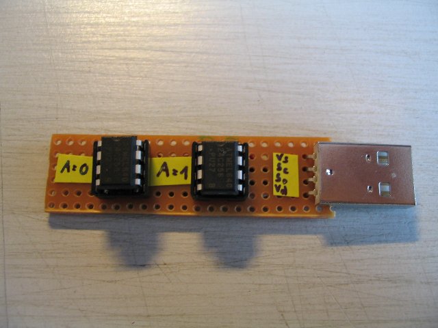
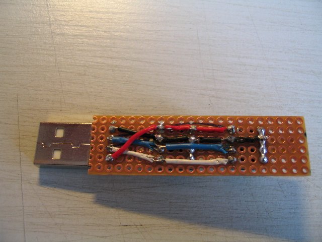
Thanks. I'm still waiting for the main-parts to start with this project. I hope they'll arrive today. Meanwhile I've build my first bankstick for my pedalboard.
-
I'm from germany and my last english-lesson is 16 years ago ;-) I've got another little question: The HD147 from Line6 includes a tuner-function. Is it possible to use it with the pedal-board?
-
Ahh,... okay. Sorry, but my english is not the best. :-) Thanks.
-
"The SongSet Menu allows for the FX1's regular presets to be organized in a custom bank to create a song and multiple songs can then be arranged into a collection of custom banks (each bank represents a song) to create a setlist." (part of the manual of the FX1 controller of Axess Electronics)
-
Hi Durisian, I've got a Line6 HD147 and I'm controlling it via the MIDI-Footcontroller MF-1 by Nobels. But I like to switch some effects / modulations without changing the preset, so I ordered the parts to build a pedal board. I've got one little question: You've written, that you need a CV Pedal or pot for the minimum setup of the pedalbox /-board. Where do I connect it? I'm a really newbie in midibox and I hope this question isn't too stupid. Btw: Is it possible to store a whole song setup with different sounds and effects, like the FX1-Midi Footcontroller from Axess Electronics? Thanks a lot. FoneBone