

Dimitree
-
Posts
63 -
Joined
-
Last visited
Content Type
Profiles
Forums
Blogs
Gallery
Posts posted by Dimitree
-
-
hi guys
perhaps, can anyone recommend me Utsource for YMF262M and YAC512C? could they be fakes? or other sources where I could buy them?
-
hi everyone
I'd like to have some suggestion for how to make a strum plate like the one used on the Suzuki Omnichord:

essentially it is a set of 12 touch sensors placed along a strip.
I thought about the SoftPot resistive strip, but I could only detect position on the strip and I couldn't trigger more than 1 signal at once.
I read about capacitive sensing but seems like there are many disadvantages.
what could be a solution?
and what do you think the Omnichord strip is made of?
-
hello everyone :)
I'm trying to understand how the Suzuki Omnichord works
this is a schematic:
Since I think it's a pretty simple device, I was wondering if I can build its tone generator around Midibox. The "Midibox side" (I mean chord generation, control program, etc) is not a problem for me since I'm a programmer, but I really can't undestand how this thing can do sounds.
Looking at the schematic those are my guesses:
the main CPU monitors the switches to decide which chord to output. Then there's a 8253 timer chip that should be able to output square waves tones. The output is sent to some dividers (upper-right on the schematic) that I don't undestand at all what are doing. There's then a circuit (on the center-right of the schematic) that makes the drum sounds (I can skip this part, I don't need it at all).
Last, on the bottom part of the schematic, there are 13 touch sensor that trigger the notes, then the amplifier and the power supply.
Looks like the sound generation is digital, the 13 triggers are only there to activate the right note coming from the digital chip.
Replacing the main CPU with a midibox should be fairly simple, but what about the tone generation?
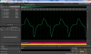
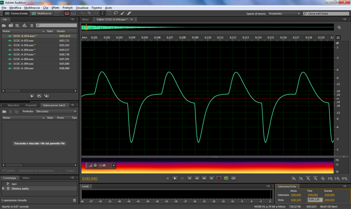
Now since I have Omnichord samples, I can't undestand how this schematic can make such waveform (at the lowest note), and then become a triangle-like waveform at the highest notes.
-
hello everyone,
I use my iPod touch + iRig Midi with midi keyboards, and it's perfect, but I can't use it with USB-Midi keyboard that don't have an actual Midi out, but just USB.
I'd like to know if there's a DIY way to convert the USB-Midi to standard Midi out.
Could the GM 5x5x5 chip could be ok for this?
-
I have 1x YMF262 + 2x YAC512.
if you are interested, tell me where are you from so I can calculate the shipping costs
-
Hi everyone,
I have for sale the OPL3 chipset (YMF262/YAC512 x2) used for MIDIbox FM / sammichFM.
I've never used those chips, I bought them from Wilba here, but I never started the project, so the price will be the same as offered by Wilba: 12.75 AUD + shipping (from Italy).
Dimitri
-
ok after some work I managed to write this thing :) it works good
only question I have now, I can't manage to put output files in differents DIRs, and take input files in differents DIRs, now it only works when files are in the same dir as makefile, and the generated files (objs, bins, lib) are created inside the same folder.
any help for this?
-
whereas the script will always build everything, which really should not be a problem for a small project.
thanks
actually that would be against the requirements, so I guess I should take the makefile route..
-
thanks TK!
yes they are only few files, just like shown..so I'd like to take the easiest way..but, the main thing is that I need this makefile for my universitary project, and the requirements are those that I wrote before..
so my question is, what you mean with commands into a shell script? would that still be a makefile or something different?
-
hi guys, this is not midibox related, but I hope it's ok to post here since it's about makefile in Linux
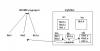
I'd like to write a makefile for a project (written in C) like shown on the picture.
Myfolder contains all the source files of the projects, and the makefile too. I'd need the makefile to:
- compile the sources
- create the static library
- link the library to the sources
- install (without the needs of root permission) the bin (and the library) in the $HOME/.myproject naked folder
- put the object files in the obj dir
- put the lib file in the lib dir
- put a copy of the bin to the bid dir
I don't even know where to start, I can only write simple makefile to compile 1 file :(
can anyone help me?
many thanks
-
It takes Note Events as well (actually that's the main thing it does).
great, I was sceptic since I haven't seen any video of MBFM used with keyboards
-
now this is another stupid question, maybe the most stupid on the forum, but I had this doubt: can I play the MBFM with my keyboard, so sendind Note-on Note-off events, or it's just CC/sequencer controllable?
-
thanks, that's a great explaination :)
-
thanks for the reply Thorsten
I don't hava undestood very well the "operator" definition.. I checked what a single operator provide (on the FM project page) but I don't understand how many operator could I need.
maybe I could help if I explain how I use FM8: I usually use 1 preset at once with no additional FX (at least not inside FM8), and no arpeggiator. I usually prefer pad sounds, soundscapes, and electric piano too.
-
many thanks again, I guess I'll add on my pcb the space to stuff transistor too, so in case the pic won't be able to drive the relays I won't need to threw away the pcb :D
next time I will search for <10mA relays
-
hi everyone
I'm not new to midibox, but just today I came across the MIDIbox FM and MIDIbox SID. I have a midi keyboard that I usually use with VST plugins, but I'd like to have a synth module to play when I don't want to use the pc. Now my question (sorry for the ignorance about synth): is the FM module a sound module able to do the same things like the Yamaha DX7 and its plugin N.I. FM8 (that I like to use)? I'm sure midibox software can cover the whole lot of settings-parameters, but what about the sound capability? Are the presets on FM8-DX7 just combinations of the sounds inside the chip?
many thanks
Dimitri :)
-
yes it's (+/-10%) 10mA, so I guess at limit?
-
thanks Nils, since I don't have much knowledge about electronics, is there a way to understand if there's enough current to drive my relay, with datasheets in the hand?
-
hi everyone
I've seen that the example on the website about how to connect a reed relay to the DOUT module doesn't use any transistor and connect the pin directly to the transistor (adding just the protection diode). I've always read that it is recommended to use a circuit like this attached to the post
is it true for reed relays too, or it will work too if connected directly, with no problems?
many thanks to all
Dimitri
-
Hi guys
I have with me a PIC18F452 and an USB programmer that can program this chip. So, could I upload MIOS in the chip without buying a pre-programmed chip. How can I burn the bootloader?
I've read this: http://www.ucapps.de/mios_bootstrap_newbies.html
but my poor english didn't help :sad:
-
Yes, it's possible to connect 4066 to a DOUT and to use them as bidirectional switches.
Connect Vss to ground, Vdd to 5V (*), CONT A/B/C/D to digital outputs of a DOUT module, and the SW pins to the circuit that should be controlled.
(*) Vdd can be higher if you plan to control a circuit that works at higher voltages - it should be at least the target voltage.
Only disadvantage: in distance to relays (or optocouplers) they are not galvanically separated from the digital circuit (MBHP_CORE, MBHP_DOUT), but if this doesn't matter you will be happy with this approach.
If bidirectional voltages are switched, you have to shift them to a mid level.
Audio signals will get some additional noise.
If galvanic separation or Audio signal quality is a *must* for your application, I recommend reed relays - they are small, reliable and silent (but they are also expensive...)
Best Regards, Thorsten.
many thanks!
so I could just connect the 4066 to the DOUT, great!
about the separation, I don't have the schematic of the board I have to control with me, so I don't know if there could be some problem. At least there's no audio signal involved. I believe the momentary switches that I'm going to force, are simple connected to +Vdd just like we would connect a momentary switch to DIN module (but I don't know if the voltage is the same, at least not higher than 5V for sure)
-
-
Hi everyone
I'm using a core to drive with MIDI 4 relays. Those relays are making a simple short between Tip and Sleeve of a jack connector, or sometimes I use it to "force" the push of a momentary switch on other circuits, like this:

Now I'd like to remove the relays (expensive and too big) and replace them with an electronic switch like the CD4066 (this one got 4 switch in one chip). Is it possible? how can I connect it to the digital outs?
many thanks
-
ci sono delle cose che non ho capito..
la prima..come mai si esamina solo il caso in cui ci sia 80 e 90 come valori del primo byte? quindi si da per scontato che il messaggio arrivi sul primo canale.. Se arrivasse su altri canali? oppure questo è solo un esempio e non un applicazione finita?
e al posto di "pin" nei parametri delle chiamate ci andrebbe il valore del pin? come sono numerati? ho cercato nella pagina "mios pin list" ma non c'è.. e nella pagina delle funzioni disponibile dice solo che riceve il pin number..

[FS] OPL3 chips set
in Fleamarket
Posted
Hello everyone
I have a OPL3 chip set for sale (2x YAC512 and 1x YMF262).
10€ + shipping costs (I'm from Italy).
Dimitri