
jbdiver
-
Posts
105 -
Joined
-
Last visited
-
Days Won
4
Content Type
Profiles
Forums
Blogs
Gallery
Posts posted by jbdiver
-
-
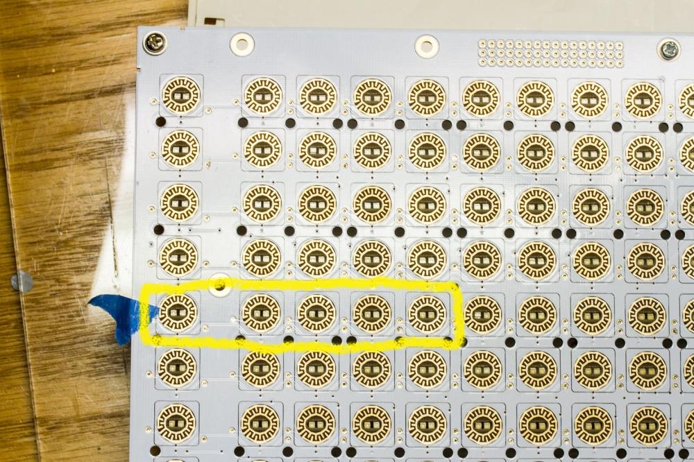
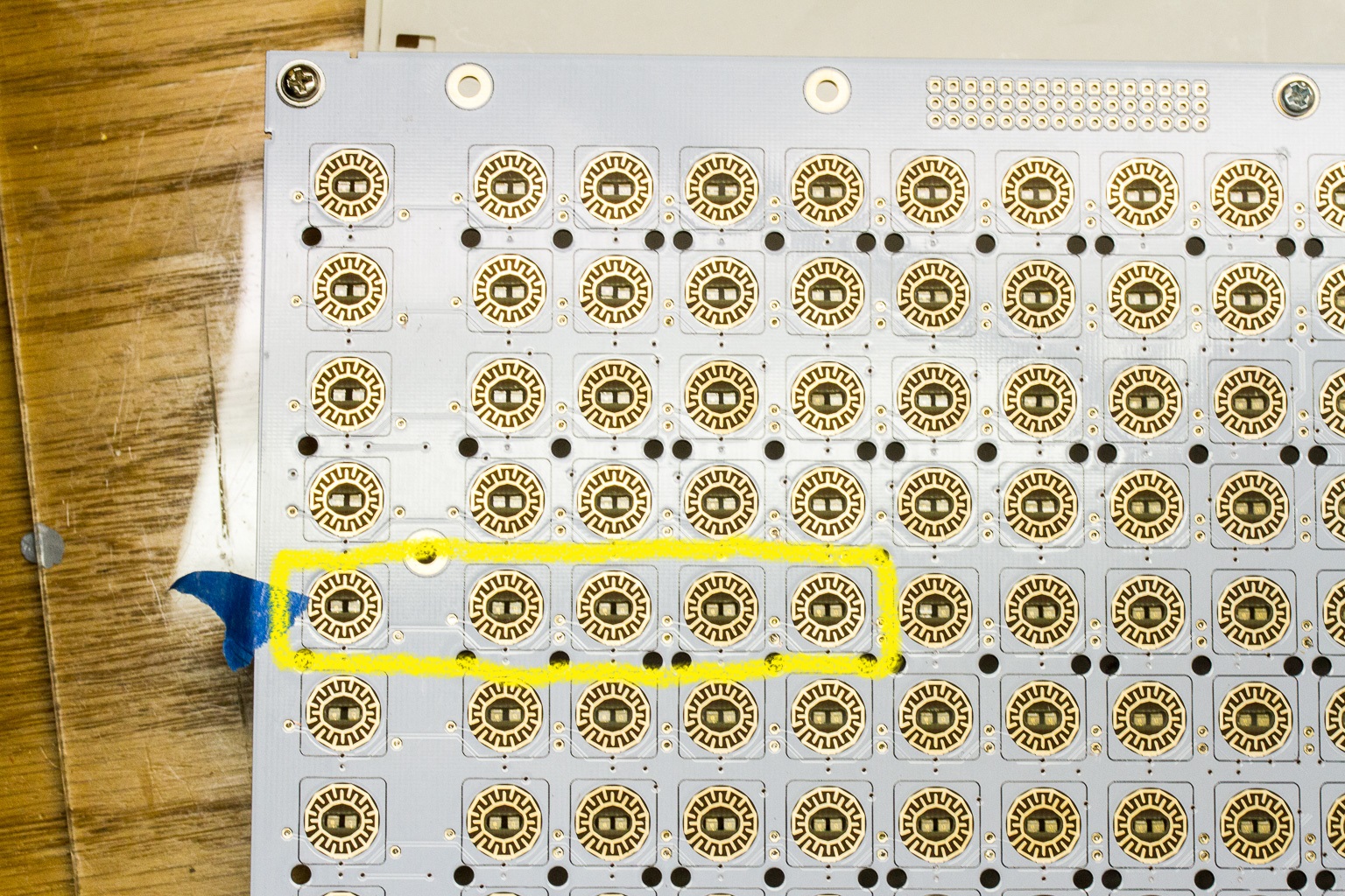
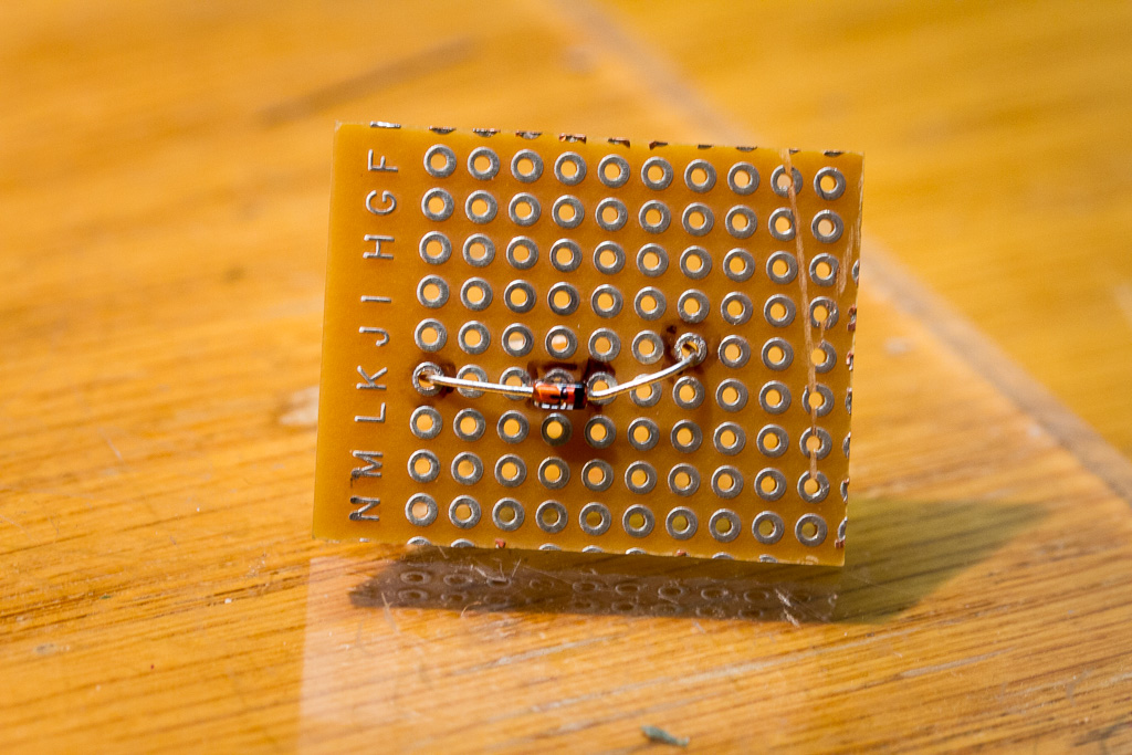
From the topside, is there a slight scratch on the trace just to the inside of the right side of your yellow box? If this trace is somehow cut, please connect cathodes on the 5th and 6th column on the same row.
You must have eagle eyes. You were right, there was a small scratch on the trace. I soldered in a little jumper on the bottom and now that section works. Thanks!
-
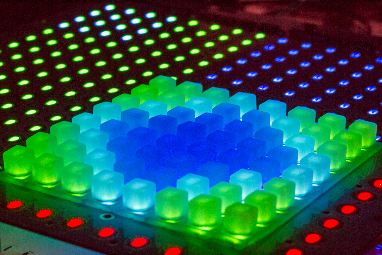
It's working! I powered up the blm from a bench supply. These are the best kind of holiday lights. :)

One small issue: a segment of 5 buttons isn't working. I've touched the LED's and diodes in this group looking for a bad joint. I've also touched around IC5 and R5. I'm not sure where to look next. Here's a screenshot showing the non-working buttons/leds:
-
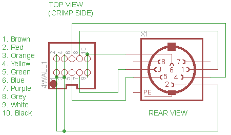
Do you have the Quad IIC installed? If not, you need to provide another MIDI connection (the input of which should be optoisolated). You can supply power via the DIN or else by using the extra case holes for a separate power connection/regulator.
I'm using the LPC17 core which has midi connections on the board. It sounds like I need to dedicate a midi i/o pair to the BLM. I have an old IIC_MIDI board (http://www.ucapps.de/mbhp/mbhp_iic_midi.pdf) that I'm not using. Can I use this board to connect to the LPC17 core and BLM? It looks like J2 on the IIC_MIDI board connects somewhere to the core. I'm not sure how the midi board is wired to the DIN. The build guide shows 6 connections between the minicore and DIN on the BLM. I'm guessing I'll also need 6 connections between the seq4 and DIN.
Some of the pins on the left header are connected (1&2&3&4, 9&10). Should I just tie these pins together by soldering underneath the header?
-
I'm finally done soldering the parts (except the sliders). Whew! I've installed the blm_scalar software on the PIC using an old core board. What unused AIN pins do I need to jumper on J5B? I can't really tell from the pictures.
The instructions show the cable pin connections between the din8 connector and the minicore board on the blm. What about on the other side, between another din8 connector and the seq4 core? I'm still using a LPC17. What should that look like?
-
I'm almost done populating the board after working a few hours each week on this project. As others have noted, this is a pretty tedious build. I worked out a method that sped up the diode installation process for me. Take a small piece of veroboard and make a little template for the diodes. You can quickly place a diode on the small board and then flip it over to trim the leads. After removing the trimmed diode from the board, trim an extra millimeter from each lead so that once the diode is placed on the pcb the leads won't protrude from the front side. I made small piles of trimmed diodes and soldered one row of diodes at a time. The diodes were easy to place on the pcb because they were already properly formed, and I never had to flip the large pcb during this process.

-
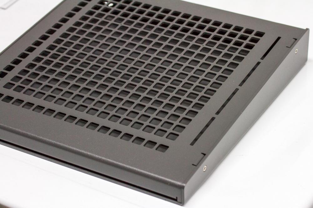
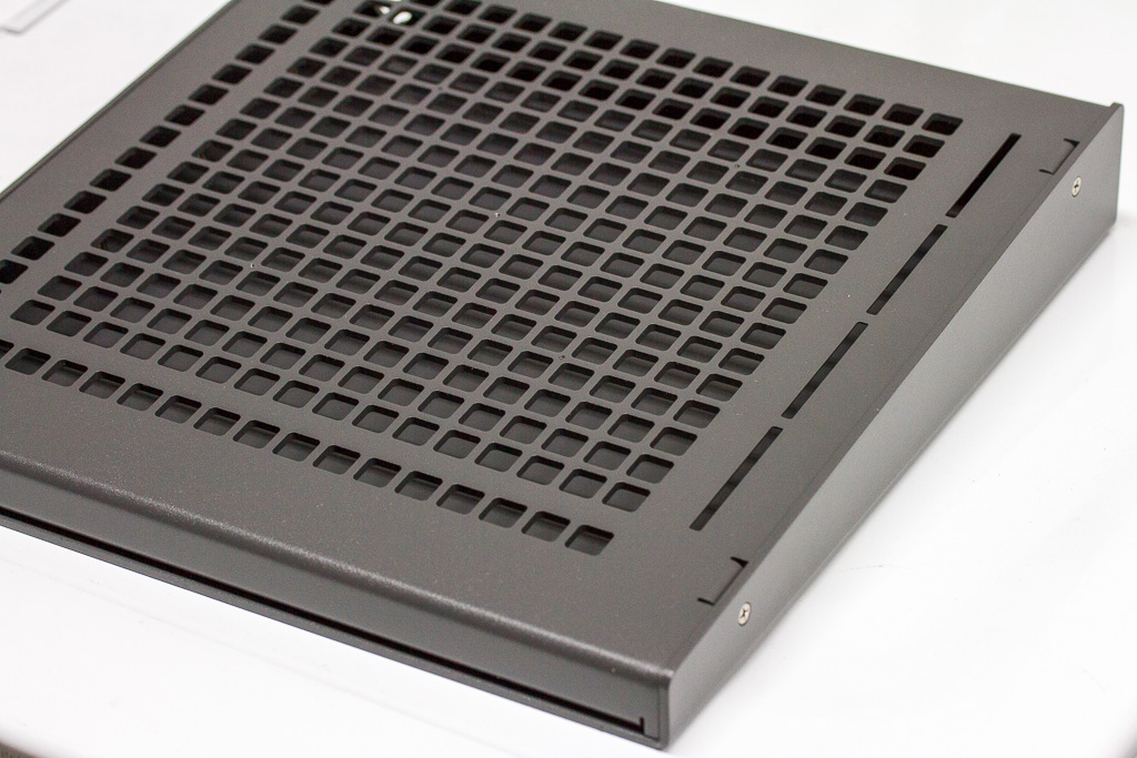
The case arrived in the US this morning. Absolutely brilliant. I was a little worried about the slope of the case and overall height, but this case looks perfect.
-
 1
1
-
-
Boards arrived in the USA today. Smartly designed packaging! Now I just need to place the mouser order...
-
Did this idea ever go anywhere? I'm thinking about replacing my lpc17 core and having to replace the backpanel on my case is a big hurdle. Are most people just using perfboard to mount I/O connections?
-
Name            PCB BLM   PCB miniCore   Case   Shift button   M2 hardware   4xLED

latigid on      1         1              1      1              1             1
Rowan           1         1              1      1              1             1
Phatline        2         2              1      2?             1             1
TK              1         1              1      1              1             1
Altitude        1         1              1      1              1             1
rwo             1         1              1      1              1             1
jojjelito       1         1              1      1              1             1
tashikoma       1         1              -      1              -             1
workspace       1         1              1      1              1             1
flyweight       1         1              1      1              1             1
Grizz           1         1              1      1              1             1
blingy          1         1              -      1              -             1
ganchan         1         1              1      1              ?             1
Macotronic      1         1              -      -              -             -
sbm             1         1              1      ?              ?             1
Jack            1         1              1      ?              ?             1
tabularasa      1         1              1      ?              ?             1
sonicwarrior    1         1              1      ?              ?             1
jbdiver         1         1              1      1              1             1

Total          20         20             16     15(+4?)        11(+5?)       18
-
It seems like there are plenty of 20x2 oled displays available. The trick is to find one with an interface and physical configuration supported by the sammichSID board. I have a sammichSID, but I haven't thought it necessary to replace the LED. I might be interested if you can find one that works. I would focus on displays that match the physical properties of the existing LED so that you can mount it in the case properly. Try a couple a let us know which ones work!
-
Definitely interested. Nice work so far!
-
The MI grids implementation sounds amazing. I've considered picking up that module many times. It would be nice to be able to tweak the three main parameters (x, y, density) using three separate encoders on the same screen. Perhaps that's easier to do if the functionality is implemented as an FX rather than as a track type. I wonder if the midi data generated by the FX could be stored to the track for later copying or manipulation.
-
You might test it using a power adapter vs. usb.
-
I'm using an LPC17 core.
-
They look awesome!
Where did you buy those? At Raystar direct?
I ordered the displays from tme.eu (Poland). I couldn't find a retailer in the US. Price after shipping was around $120 USD. I held off on this upgrade because I wasn't sure the expense was worth it. Now I could never go back to lcd's.
-
So mounting holes match up?
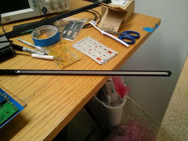
Yes, the mounting holes and display window match. The only issue is that the vertical width of the pcb is longer (maybe like a cm) than a typical lcd display. I was able to solve this issue by having a machine shop modify my case.
-
Wow those look fantastic. Do they seem any brighter to you? They look way brighter than my current LCD's.
The characters are definitely much brighter than the backlit lcd's. Plus, the background is black so the characters really stand out. I can sit 3ft (1m) to the side and still clearly read the displays.
-
I recently replaced the 40x2 lcd's in my Midibox SEQ4 with OLEDs from Raystar. These OLEDs are drop-in replacements for standard lcds and work perfectly with the midibox platform. I think they look incredible. The power savings is nice as well.
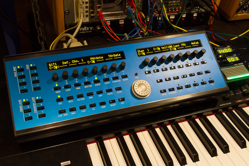
One important note is that if you are using the Heidenreich case, you will need to have a section of the top curved bar milled out by a machine shop to accommodate the OLEDs. The vertical width of the displays are noticeably longer than standard lcds and the display pcb will interfere with the bar if a section isn't cut out.
-
The 7-segment displays can be purchased from: http://www.kingbrightusa.com/. They will ship internationally. While ordering directly from the manufacturer is more expensive, you can choose from a larger assortment of colors and intensities. I used part# SC39-11CGKWA for my TPD.
-
Update: TK identified the MUTE/UNMUTE ALL LED issue and gave me pre-release software to test. I confirmed that the updated software fixes this LED issue.
-
If I assign LED_MUTE_ALL_TRACKS to one of the LEDs on Wilba's panel, the LED does not light properly when the assigned button is pushed. I tested several other functions with the TPD LEDs and all of them worked. It's pretty clear to me that this is a software issue. Specifically, the two MUTE/UNMUTE ALL functions are not controlling LEDs properly.
One interesting note is that when the LED_UNMUTE_ALL_TRACKS is assigned to an LED, the LED is lit when the sequencer is turned on. This makes sense because none of the tracks in my current working sequence are muted. However, if I mute one or all tracks the UNMUTE_ALL_TRACKS LED stays lit.
Here are the states I would expect to see for the LEDs:
No tracks muted: UNMUTE_ALL_TRACKS (on), MUTE_ALL_TRACKS (off)
One or more tracks muted: UNMUTE_ALL_TRACKS(off), MUTE_ALL_TRACKS (off)
All tracks muted: UNMUTE_ALL_TRACKS(off), MUTE_ALL_TRACKS (on)
I've attached my hardware configuration using Wilba's panel and the TPD with the following assignments:
SW1/LED1: MUTE_ALL_TRACKS
SW2/LED2: UNMUTE_ALL_TRACKS
SW3/LED3: TAP_TEMPO
SW4/LED4: (empty)
Encoder button: FAST
-
Yes, I can confirm LED4 lights red when Pin 0 is assigned to LED_TAP_TEMPO. We are both seeing the same results. Thanks for your help sorting this out.
I can get the LED's to behave property when assigned to LED_TAP_TEMPO, but not LED_MUTE_ALL_TRACKS or LED_UNMUTE_ALL_TRACKS. For example, I assigned button1 (SR7 Pin 4) to BUTTON_MUTE_ALL_TRACKS and LED1 (SR11 Pin 7) to LED_MUTE_ALL_TRACKS. When I push button1 the sequencer responds by muting all tracks and displaying a notification on the lcd. However, LED1 does not light as expected to show that this feature is turned on. I'm guessing this is either a software configuration issue (something else is required in the config file to enable this behavior) or it represents a software fault.
-
My tests definitely do not match the specs. I re-ran my test configurations tonight
I assigned BUTTON_TAP_TEMPO to button3 (SR7 Pin 6). Next, I assigned LED_TAP_TEMPO to a variety of SR/Pin values. Here's what I saw when activating button3:
LED 1 (red): SR 11 Pin 3
LED 2 (red): SR 11 Pin 2
LED 3 (red): SR 11 Pin 1
LED 4 (red): SR 11 Pin 4
LED 3 (green): SR 11 Pin 5
LED 2 (green): SR 11 Pin 6
LED 1 (green): SR 11 Pin 7
Note: I have a hard time telling the difference between red/green LED's, so it's possible I recorded one or more of these test results incorrectly. I didn't see any LED's light when set LED_TAP_TEMPO to SR11 Pin 15.
I traced all of the connections from the U9 pins to all of the LED's. I also traced all of the remaining connections between U9 and other connecting points. All the connections for U9 tested okay.
-
Okay, thanks for the help guys. I'm very close to finishing this configuration. The LED assignments for the TPD (using Wilba's frontpanel):
LED1 = SR11 Pin 3
LED2 = SR11 Pin 2
LED3 = SR11 Pin 1
LED4 = SR11 Pin 4
The problem I'm encountering now is getting the behavior of the LED's to match the associated button function. For example, button1 is assigned to BUTTON_MUTE_ALL_TRACKS. Next, I assigned LED_MUTE_ALL_TRACKS to LED1. When I activate button1, the LED1 doesn't light. I must be missing something in the configuration. ??
I assigned button3 to BUTTON_TAP_TEMPO and LED3 to LED_TAP_TEMPO. That button/LED config seems to work just fine. The LED3 lights each time I tap button3.
BLM 16x16+X build guide
in MIDIbox BLM
Posted
Ah, I didn't know about this board. I've got an old IIC_MIDI board and two of the newer MIDI io modules (http://midiboxshop.bigcartel.com/product/midi-i-o-module-board). There's too many of these midi boards available to keep them all straight. ;) I just ordered this quad midi board from Tim.