kaleaf
-
Posts
47 -
Joined
-
Last visited
Content Type
Profiles
Forums
Blogs
Gallery
Everything posted by kaleaf
-
No luck on other pc's with different os's and midi hardware. Will get a regulated 12v and test.
-
yo, i replaced the 2200uf i also bought a bridge rectifier... i started a new thread because I did not think the problems were related
-
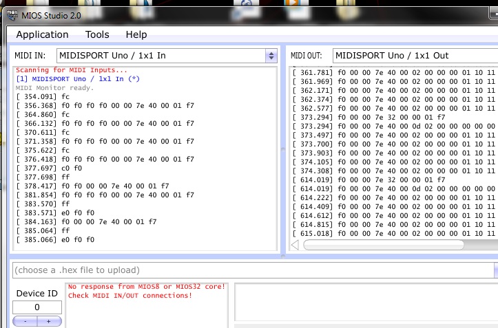
My device is getting weird extra data in mios. The device loads mios and says ready. extra f0 f0 f0 before ID Research in mios guide and this forum post said maybe bad filter cap so I replaced the 2200uf cap, maybe thats not the one, anyway still error. - this post Going to try a xp pc next and I bought another bridge rectifier if that might help. Using a 9v 1a power supply, tried other 9v and a 12v. Any Ideas
-
Got it to power on and show ready. Could not query device. Saw I was getting f0 f0 f0 before the id message and research said that might mean a bad cap. Is that the big blue cap?
-
I think I had a short between big blue cap and the small yellow one next to it. Here is my voltage results 5 volt connections (J2) --- 5.01v 9v connections --- 8.92v (J20 and sid pin top right) 12v line --- 13.39v (from backlight header) is that 12volt line at 13.3v going to be a problem? ---edit i read the f'n manual (btw I blew my 12v dc supply somehow maybe it wasnt regulated)
-
So I touched up my soldering on the rectifier and the 2 caps under it. When I tested I was no longer getting any reading at all. I switched back to the 9v ac. I think it might be working now!! J2 now shows power without JBP shunts and with jp in the right mode, yay With the 12v dc I get no readings though, maybe I blew the supply, I noticed at one point the rectifier got really hot and I herd a slight click maybe from the cap, maybe from the power supply. It still seems a little weird going to test this supply. any reason dc power would stop working on the board? Wilba I really apprediate the help, I understand how hard it can be to troubleshoot remotely, im a network admin, will report back later after I check out this supply.
-
when testing the voltage off top right sid pin no shunts - no power JBP shunts on, no JP shunt - 0.29v JBP shunts on, JP in 6581 mode - 12.55v JBP shunts on, JP in 6582 mode - 8.92v JBP shunts off, JP off - 0.14v JBP shunts off, JP in 6581 mode- 0.62-1v JBP shunts off, JP in 6582 mode - 0v no cross connects on JP or JPB going to clean up soldering on rectifier
-
I ment when in 6581 mode on JP mode with JBP's on I get power. When I am testing the only way I get power is with the right JBP on when I take it off the board is dead. -testing no shunts - no voltage right side JBP shunt installed - can read voltage with any other combo of shunts or with other shunts removed any other combo of shunt without right JBP - no voltage -power supply tip positive symbol 12v (symbol for dc) 1a i do not know how to tell if its regulated I thought dc means regulated but I might be wrong
-
hello, I am doing the final voltage check before I install IC's. I am reading 0v from the ground to all the power spots (blue/purple dots on instructions). I checked for crossed connections with the beep mode and everything seems as it should be there so I think I must have fried something. Not sure where to go from here. Maybe you guys can help me narrow it down. I can get some readings from ground to rectifier. I am using a 9v ac 1a , also tried other 9v ac's and a 12v (not sure if it regulated). I can post my readings from rectifier but not sure what supply to use. ---update--- with jbp header on the right set I can read 5v from J2 hope this narrows it down I have been thinking it might be the big blue cap because before I put it in one of the legs felt kinda loose does that sound like it could be it more info --with jumpers in 6581 mode 12v dc power 5v reads 5.01 9v reads 8.92 12v reads 12.73 9v ac in 6581 mode reads 1.2-2v on 5v,9v,12v spots -- with jumpers in 6582 i get nothing
-
Thats cool I will finish it up then. At my local shop they did not have any that were in nF range, and it was the same on mouser, so I just figured out to change it to 0.1 uF and I think I found the one. mouser 80-C317C104K5R5TA I will add it on next time I get something from mouser. Thanks for the info TK.
-
arg I messed up and put one of the caps in the wrong spot and I had to cut it off. I could not find the cap at my local store and not having any luck finding it on mouser. I need part number for the 100nF monolithic cap if possible. mouser prefered
-
Again I am bad at decisions, I ordered 2 lcd's and the extra I will use on the midibox controller I have yet to finish.
-
That would be cool. Sometimes I just get stuck on the choices.
-
I am ordering my lcd. I got red led's and I think a crystalfontz blue text on black might look nice. Anyone have any experience with blue lcd text I am worried about reading it in the dark and I might go with a brighter color text. If I buy 2 lcd's and decided after testing them what legnth male lheader pins do I need for the lcd side of the connection?
-
Hey SOLO its kaleaf from the djtt forum, I think you got the wrong core and you need the regular one. also http://www.mouser.com/catalog/catalogusd/639/1589.pdf thats mouser catalog for pushbuttons tons of stuff in there look for momentary switches with solder points (lug) or surface mount if you want to put them on a pcb breadboard. I will be at a festival untill 10/19 but I would be glad to help you look for parts when I get back in a few days, I need to get more parts also.


-
Hi Wilba, Is the PCB + Parts on your bulk order page still available? Also is there a bulk order going for the front panel? I checked the bulk order page and I am not sure if it is still open.
-
Thanks for the book info also.
-
They don't have dual gang in the bourns brand its not a option. http://www.bourns.com/ProductLine.aspx?name=sliding_panel_controls (in the ptl series the options/ganging is blank) I have found one possibility with another brand but its not on mouser so my chances of getting just a few are very low. You guys know how it is when you make something and you get picky. Im going to try and test the taper with the light hooked up and if it makes it more like a audio taper it might be ok.
-
Madox and TheProf .... I thank you for your help. Madox, my background in electronics is just from projects I have done and a few things at work. I have made lots of rs232 cables at my work and I have good soldering skills. My interests has been recent after finding diy audio projects like midibox and diy synth kits. I like synths alot I have taken a course at my local community college on synths and I have always wanted to get my hands on a analogue (I use software at home). For me right now I am more intrested in learning what to do to make a dimmable led (from a single gang pot) in general than I am worried about having this exact one do it. Doing it right is important to me and by that I mean not affecting the linear taper of the pot. If I have to hold off on this untill I learn more I will still do my project. I have learned a few things researching this question and from the tip about opamps if I use them or not it all helps. thanks again I will get back after I have time to do some multimeter tests
-
"Power and ground pins can only source/sink 30mA max current per pin. Total current draw must not exceed 500mA If you need more current than 30mA then you can use one of the fixed power pins on connector J7. See the U-Config program board image for details of which pins these are. In fact it is good practice to use these pins whenever possible for a 5 volt source as they are powered directly from the USB supply." thats from the specs. so I think it can dish out the full amount of the usb spec 500ma. My skills are very basic. I know resistors, pots, and basic circuits, but im still reading about stuff like opamps. I have good soldering skills.
-
thanks guys this is the device I have http://www.u-hid.com/ its a usb-hid board that has 50 pins. The slide pot with accept 5v from the board and connect to a analog input 0-5v pin on the board. The board can control leds aswell but not for the analog axis(the slide pot). I will have the sliders soon so I will come back when I have them to test. I think I am looking for a way to split the output on the pot so it can go to the uhid and adjust the led also. Dual-gang was not available for the led sliders.
-
Hi im looking for some help with some led potentiometers that I have ordered. http://www.mouser.com/Search/Refine.aspx?Keyword=PTL60-15O1-103B2 I am trying to figure out how I am going to make the led dim at low. I am thinking about powering the led off the resisted signal side of the pot but it would make my pot nonlinear. Im running 5v through the pot to a usb hid encoder This is for a usb-hid project and I have found this forum and it has been very helpful because I am using similar controls (Im building a traktor dj controller). If I have good luck with this one I hope to build a midibox and some sequencers. If you guys don't do non-midibox questions let me know, I have not found a good forum my project is a mix of random stuff (mostly arcade parts so far).
-
Thank you sir.... Have a good new years