WickedBlade
-
Posts
54 -
Joined
-
Last visited
Content Type
Profiles
Forums
Blogs
Gallery
Everything posted by WickedBlade
-
1kHz noise, how to get rid of it?
WickedBlade replied to WickedBlade's topic in Testing/Troubleshooting
It makes sense, and it's more or less what I had understood. I'm just surprised that the input current is varying so much (since the 1kHz noise comes from another circuit entirely, with only the ground in common). As I said, I do have a 7809, and I'm using an external 12V DC supply, so I'll manage to get at least 9V. I'd like to do better though, so I'll try the diodes trick to get 9.7 or 10.4V if possible. If worse comes to worse, I'll just use the 12V supply directly, since I took the pains to buy a linear power supply, no switching involved. Thanks again. -
1kHz noise, how to get rid of it?
WickedBlade replied to WickedBlade's topic in Testing/Troubleshooting
Hmm, I haven't had a real look at the MBFM, to be frank :rolleyes: Part of why is because I'm not really "creating" the audio, just sort of distributing it, so it's not the same use. As for power supplies, well I'm building a pedalboard so I was trying to avoid clustering the case or the floor with more transformers. As it stands now, I don't have any space left in my case to add another power supply input or a built-in transformer... This would need some serious reworking and I'm hoping to avoid that or the project will be canceled due to too much trouble... Or I'll just dump the buffers and only use the relays, this way the audio and digital will be totally separate, but I liked this feature and will try to keep it viable for as long as possible. Thank you for your help. -
1kHz noise, how to get rid of it?
WickedBlade replied to WickedBlade's topic in Testing/Troubleshooting
I'm trying to find references about the diodes trick for the power supply. Mainly I want to make sure I'm not putting the diodes backwards. I have only been able to find this: Three different ways to change the output voltage of a 78 series regulator Can you confirm that this is the correct way of inserting the diodes, with the anode towards the 'real' ground? Also, is the cap necessary and if so, is the value suggested correct? Of course, if you have more precise websites on the subject, I'm interested... Thanks! -
1kHz noise, how to get rid of it?
WickedBlade replied to WickedBlade's topic in Testing/Troubleshooting
All right, so it looks like I'm going to use a 7809 with one or two diodes to get ~10V, and I'll rework my grounding and we'll see what comes out of that. Thanks guys. -
1kHz noise, how to get rid of it?
WickedBlade replied to WickedBlade's topic in Testing/Troubleshooting
Really? I had no idea that the resistors might be a problem! I got the circuit from a 'reknown' source, someone who seems to be well regarded on the net. Heh, go figure... Anyway, I'm using resistors because I'm trying to get as much voltage (hence headroom) for the opamp as possible. I'm currently getting about 10.15V (with different resistor values), and I'd like to stay in this area (considering that I'm feeding a 12V DC and the voltage drop from vregs, I can't get much more). The only other spare vreg that I have is a 7809 which would reduce the voltage a bit... You mentioned that I could use diodes instead of resistors. Would that fix the issue? I'm interested in any pointers you'd have as to how to do that (I'm not an electronics expert, as you have guessed). Now, I know that I could feed the opamp directly from the diode bridge and I would get about 12V (minus the diode voltage drop), but I was trying to be future proof and deal with higher power supplies... It's still a possibility, though... -
1kHz noise, how to get rid of it?
WickedBlade replied to WickedBlade's topic in Testing/Troubleshooting
Thanks for your input. Unfortunately, for practical reasons I can't really get 2 (external) power supplies, which was the obvious solution (I've thought about it but had to reject it because it is impractical for me). The sloppy construction method is definitely not out of question, unfortunately, but I've checked my work a lot and can't find any fault that would explain the noise. As for the buffer and opamps, I don't need bipolar supply because I'm using a reference voltage to 'lift up' the signal and get it back to 'normal' at the output thanks to a capacitor. The schematics is basically the one found there: AMZ Super Buffer. What's different is that I'm using only one opamp, let's say IC2b, and resistors R1-R3 are taken out too. I've actually built 2 reference voltage, one for each half of the opamp, which is not actually necessarily, I think, but shouldn't hurt. About the schematics, I should point out that I've tried to represent the actual way that the wiring is done, and most importantly, the power really splits at the C1 cap, and its pins are the only place were the 3 power supply subcircuits meet, so I'm thinking that noise from the digital path should actually go through C4 then C3, IC1, and C2 to then go back the other way through C9, IC3, C12, and C11. It looks like very bad luck to me that it manages to do just that... I'll have another look at my ground wires though... -
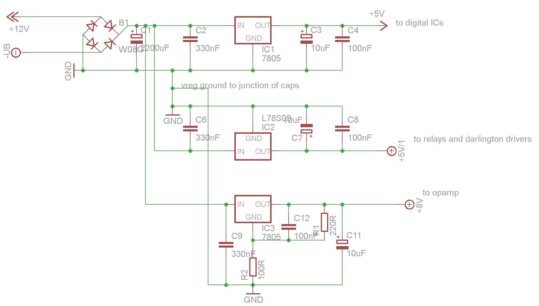
Hello, my project involves both audio and digital path, and I'm getting some noise from the digital path into the audio path. I'd like some advice as to how to minimize it. Now, for further details. I'm using one CORE, 2 DOUTs, 1 DIN, and a custom relay board that is triggered with some of the DOUT outputs (I'm using darlington arrays and everything). The MIDIBOX modules all come from Mike's shop and are unmodified except for the power supply, which was taken off the CORE module (I had the same problems when it was still on the CORE module though). On the audio path I'm using a dual opamp to make 2 impedance buffers, and the relays I mentioned before are used to route outboard effects in and out of the signal path (I'm basically building a MIDI effects switcher). I've done all I could think of to avoid ground issues (ground loops and all), I'll come to it later. My problem is that there is some noise coming from the digital space that goes into the audio path. The noise is basically 1kHz, and I've determined that it is directly related to the frequency to which I've told the PIC to update the DIN/DOUT (and it's there even if I don't actually call updates for the DOUTs). Taking the DOUTs or DIN off the system makes the noise disappear, I think that's proof enough. I've made sure that each module is acting for some part in the noise, and the sum of them makes the overall noise worse, of course. For the record, I did put bypass capacitors on the shift register power supply pins. As far as power supplies go, I'm feeding 12V DC to my system, which gets first through a diode bridge (just to be safe), then to a 2200uF cap, and then splits to feed 3 power regulating circuits. An image is worth a thousand words, so you'll find attached the schematic for the power supplies, I hope they're clear enough (ignore the voltages I give though, they're not correct). So basically I made sure that the audio grounds are wired almost directly to the ground of capacitor C11, the darlington arrays are wired to the ground of C8, and so on and so forth. I was hoping to have different ground spaces this way (I'm voluntarily not using the word 'plane' here), but it doesn't seem to suffice. I get some low noise when the buffers are inactive, and a lot more noise when they are active. BTW I have 2 buffers, but the noise level doesn't change much between when only one buffer is active and when both are. I'd like to know what I can do to resolve this issue. Add new capacitors with different values? Rework my grounding? I believe I could make 2 separate grounds (one for the digital path + relays and one for the audio/buffers) but I'm not sure how I could achieve that exactly. Any help appreciated, I'm nearing completion but my project is worthless if I can't resolve this.
-
Thanks. I'll get my eyes fixed ASAP :geek: :blush:
-
I don't know if I'll try that yet but you might be interested to know that Recom makes a switching regulator that is pin compatible with the good ol' 7805. It is the R-785.0-0.5 and R-785.0-1.0. The first one is rated for 500mA output, second one for 1A. They're a bit expensive, but they might be just the thing. Rapid online offers them, but I'm aware of no other shop having them europe-side. If somebody does, do share!
-
Hello, this may not be the right place and this may have been discussed elsewhere, but if so I missed it and sorry about that. Anyway, as you can see I still have my forum account but it looks like my Wiki account has disappeared: I can't login and if I go the "forgot my password" route the wiki tells me my user name is unknown... What gives? And more importantly, how do I fix that? I didn't see a "register" page on the wiki... Thanks!
-
Thanks. I'll try to move the CORE 7805 somewhere where I'll be able to use a heatsink... Or I'll try to use a common 7805 for the digital path and relays...
-
Thanks for the help guys. philetaylor, I'm afraid that $15 is a bit too much for me, but thanks for confirming that the heat comes from a big drop. lylehaze, thanks for the formula... My project currently uses 3 voltages, and hence 3 vregs. One for opamps in the audio path (~10V), one for the relays (5V), and one for the MIDIBOX modules (5V). The two 5V vregs are currently separate because I wanted to avoid noise whiplash in the relay coils that could reach the audio path (call me paranoïd). So the 5V from the CORE Vreg is only digital. I guess that a switching vreg would work, then... Do you have a part reference I could use? The LM2575 is not a direct replacement (it has 5 legs) and I would prefer that, if there is such a thing... Also, the vreg I use for the relays is a L78S05 so it can handle a bit more current and maybe it could handle the digital path too, but I've already added a heatsink because it's very hot as it is...
-
Hello all, apologies if this was asked before and/or if it's posted in the wrong place. I did a search but didn't find an answer to my question. So here it is. I use a 12V non-switching PSU for my project because I need more voltage than the CORE module needs to feed relays and stuff. So currently, my 12V PSU goes into the CORE 7805 vreg. The problem is that 12V to 5V is apparently quite a drop and the vreg gets really hot. There's no room on my CORE board to fit a heatsink so I'm stuck. I was wondering if there was a replacement available that would maybe use another technique to avoid so much heat loss... (I've seen the LM2575T for instance but it has too many legs...) Would it work? If not, I'd like to hear about other options. The obvious one would be to offboard the vreg and use a heatsink, but I'm thinking of using an intermediary vreg (say, a 7809 that I have handy here) to feed the 7805 (bypassing the rectifier bridge, or rather, placing it before the first vreg, of course), maybe both would produce less heat together than the 7805 alone... Thoughts?
-
Oh, I see. They are actually flags that I should sum up. I haven't had the time to test yet, but seeing as I have the datasheet for my encoders, with a diagram, I could perhaps guess the correct values, right? The datasheet is there: EN12 encoder The diagram is at the bottom of the last page. I would have thought that it was a regular DETENTED2 encoder, though...
-
I... think I understand what you're saying. I suppose this is explained in the topic that TK mentioned, but I don't speak german at all... So if I got it right, I can specify custom modes instead of DETENTED2, DETENTED3 and all, just by choosing one of 4 available modes for increments and decrements. That would make for 16 possibilities. I'm not sure this will help, because if I use a mode other than DETENTED2, the increments are no longer units but bigger figures... But I'll try anyway, it can't hurt... Thanks.
-
Thank you for your help, TK. I updated to MIOS 1.9g (and rebuilt my app with MIOS base 1.1 of course) and tried all the detented modes. Only mode DETENTED2 worked (almost) correctly, the other modes gave completely incorrect increments. I played a bit with the MIOS_ENC_SpeedSet too. It was initially set to fast mode, with a speed of 2. I tried slow mode (with speed 0) and normal mode, and also a couple other speeds in fast mode. The normal mode is the one that gives me the less incorrect behaviour. This is kind of expected, since apparently I'm getting jitter, which the fast mode would interpret at a greater speed, hence bigger increment values. Any idea what I could do to avoid this jitter? I rather liked the initial Fast 2 mode...
-
Hello again, my application is working rather fine as far as inputs and outputs are, but I'm experiencing a slight problem with encoders. I have 2 of them, they work almost always fine but I experience strange increment values from time to time. My test app just displays a value between 0 and 99 on the LCD and the encoders are used to increase/decrease the unit and ten digits respectively. So if I start at 00 and I turn the unit encoder clockwise I get 01 then 02 etc. But it sometimes happens that the value jumps around, for instance it goes from 02 to 07 instead of 03. It's the same with both encoders. I can also get positive increment when turning CCW sometimes. I'm not sure, but it seems to be more frequent when I turn the encoders very slowly. These are detented encoders and by slowly I mean staying out-of-dents for a short time. I've currently declared them as DETENTED2. Is this a problem with the detented type, or is it a speed value, or is it simply that my encoders are not the best quality and I get bounce from time to time? If so, how would I go about fixing this in software? Any idea? Thanks!
-
If anybody cares, I'll answer my own questions, in the hope that it may help someone: My settings on MIOS Studio were wrong. First, it's easier to hide the internal settings, second, a good routing would be thus: In the optocoupler test circuit, if you are too far from 0.1V when the switch is closed, this isn't good. I've experienced myself that 44mV is bad, and I've seen posts hinting that 70mV is bad too... No idea of a correct range The sysex message "F0 00 00 7E 40 00 01 F7" is the upload request, it should appear in the MIDI IN monitor of MIOS Studio when you fire up your MIDIBOX. Only once if you have a MIOS already uploaded, repeatedly if you only have the bootstrap loader. FWIW I bought a new opto, it arrived yesterday, I popped it in and it worked. So yes, as everybody already knows, the optos are fragile things, it's better to order a few spares.
-
Sorry for asking so many things but I'm not sure I've routed my devices correctly in MIOS Studio. If I didn't I may be sending things incorrectly, right? This is my current routing, is it correct? The PC is connected through the MPU-401 interface.
-
I did the loopback test as explained here: http://www.ucapps.de/howtodebug/mbhp_core_extract_io_loopback.gif And nothing happens, the signal my PC sends doesn't get back. So I guess it confirms there's something wrong with MIDI IN. I measured and checked the signal path on my CORE at various points around J13 and the optocoupler and was able to confirm that the signal path is OK and R5, R6, and R11 have the expected values. I confirmed that I had ground and +5V at the expected locations too. So I guess it means that, indeed, my optocoupler died on me. What I don't quite understand is, if I had just stopped at the optocoupler test (mentioned earlier), I would have guessed that it worked correctly, what with reading 44mV when the switch is closed. Apparently, though, this is not a correct value. Can a knowledgeable expert confirm that this is indeed too far from the expected value of 0.1V? This might help others... What is the acceptable range around that 0.1V value? Thanks.
-
Alright, with the correct circuit I measured 44mV between pins 6 and 5. Could this be too small a value?
-
Well yes, that's what I'll try ASAP, but it will take a whole week for one to get to me, so I'd like to check that it's indeed the optocoupler's fault in the meantime, just in case, you know... I'd rather not wait for a new one to find out much later that it wasn't the culprit... I measured stuff again, and I find one thing strange. When the switch is closed on the test circuit, I measure 4.98V between pins 6 and 5, as I said. But, stranger still, I measure 1.8V between pins 8 and 5. How is that possible? Shouldn't I at least be reading 5V there?! I'm using the +5V and ground supplies from connector J9 on the CORE, by the way... How come the vreg doesn't keep giving me 5V... The PIC and LCD seem to be working fine at that point, though. I'm thoroughly dumbfounded! EDIT: Well, I failed at building the circuit tester. Will try again and keep you posted.
-
So I've built (awkwardly) the optocoupler test circuit as seen there: http://www.ucapps.de/howtodebug/mbhp_core_opto_test.gif If I built it correctly, then I think I have a fried optocoupler on my hands. The thing is, I'm not sure of it. Yes, I've double-checked my circuit, but, you know, once you start doubting... So here's the thing: I know for a fact that my MIDI cable and the MIDI port on the PC side is working: it works with other MIDI devices that I have, and it also worked with the very same CORE module weeks ago, I used it to upload MIOS to the CORE! the optocoupler has worked before (I used it to upload MIOS, and a few days later to impress my girlfriend with the LCD debug message from MIOS Studio) I may have fried it by plugging the MIDI plugs in the wrong order (IN with IN and OUT with OUT), though I fail to see how plugging 2 optocouplers together (one on each site of the MIDI connection) would lead to frying one (and apparently, not the other) the optocoupler testing circuit measures 5V when the switch is open... but I have 5V too when it's closed! I'm a bit surprised at the latter value. I was expecting something maybe too big, at least bigger than the specified 0.10V... But 5V! That's what's making me doubt my circuit... I should mention that as I didn't have any 1k or 1.2k resistor, I used a 1.1k that I had. I figured it should work the same. Was I wrong? I'd very much like any opinion on that, please help, I'm getting nuts!
-
Thanks for the help. Well if I fire up my CORE module + LCD it does work correctly. Now that I plugged the MIDI in/outputs correctly, I do see the incoming SysEx message (F0 00 00 7E 40 00 01 F7, does this mean anything besides an upload request?) but I don't seem to be able to send data through the MIDI in port. I tried the LCD Debug feature in MIOS studio, it doesn't work. Likewise, Hex update doesn't work. (BTW I had already uploaded MIOS v1.9f some weeks ago when everything was working). Of course I tested my PC ports by using another MIDI device, it works. So it looks like I have no MIDI in. I checked the wiring/soldering from the plug to the optocoupler, and from optocoupler to PIC, it looks to be OK. I'm wondering if I haven't fried the optocoupler somehow? Either that or I partially fried the PIC, but that is unlikely (I get SysEx 'welcome' and the LCD works fine), and that would be awful. So what next? I guess I'll have to build the little optocoupler test circuit tomorrow...
-
All right, it looks like I mixed up the entries on the PC-side and actually plugged the PC MIDI Out to the MIDIBOX MIDI Out (instead of OUT with IN) -- my PC cable is a bit vague as to which connector is which. I had a look at the MIDI specs for the PC cable (Sound Card Game Port to MIDI connector) and it looks like this would effectively connect the PC +5V signal to the MIDIBOX +5V signal through 2 220 ohm resistors (one on each device). So it looks like it could result in some remote powering of the CORE... Unless I got mixed up regarding pin placement in the DIN plugs... I'll try plugging my device in the correct way later, hoping I haven't fried anything... I'd still appreciate some opinions on that, though.