

MONSTA
-
Posts
87 -
Joined
-
Last visited
Content Type
Profiles
Forums
Blogs
Gallery
Posts posted by MONSTA
-
-
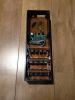
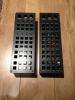
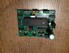
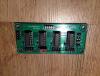
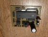
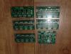
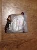
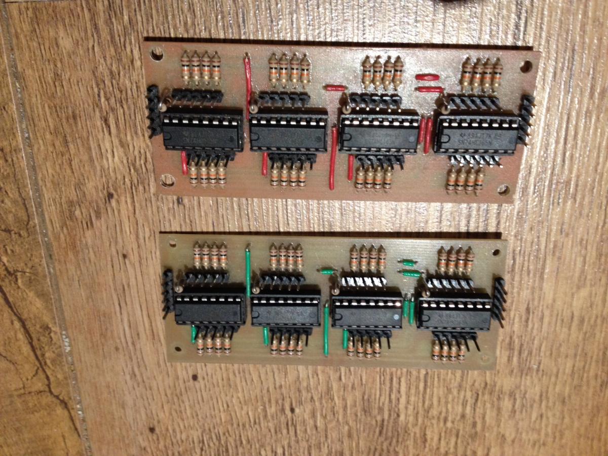
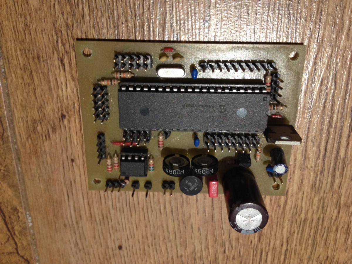
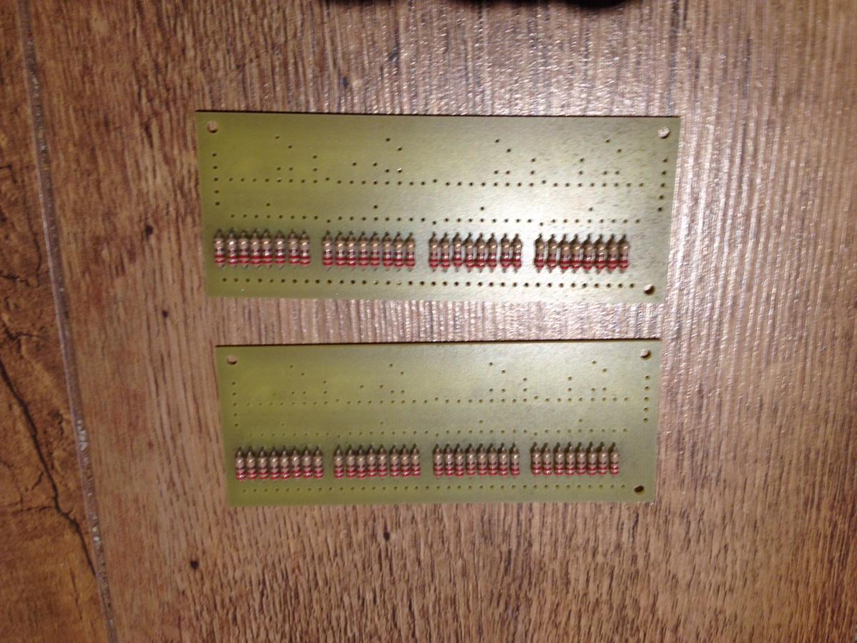
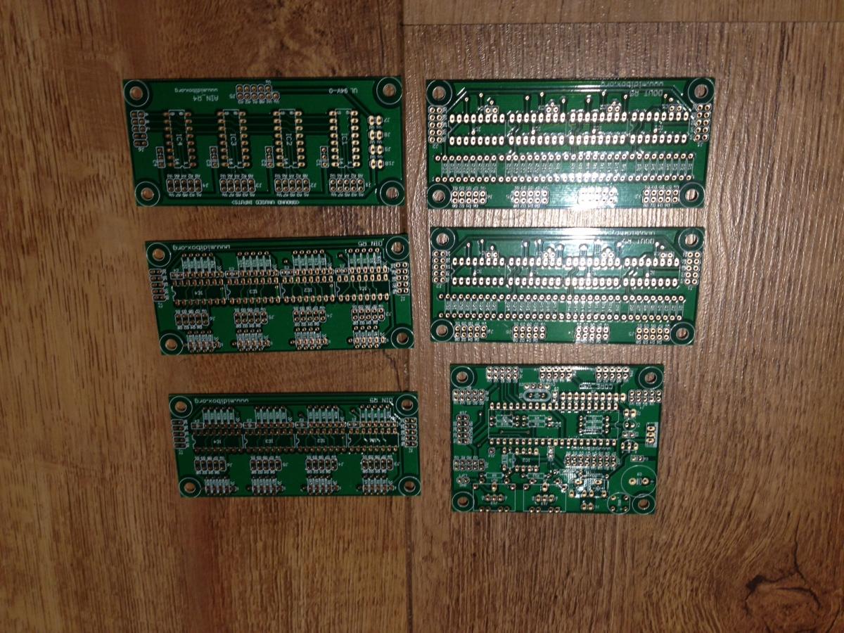
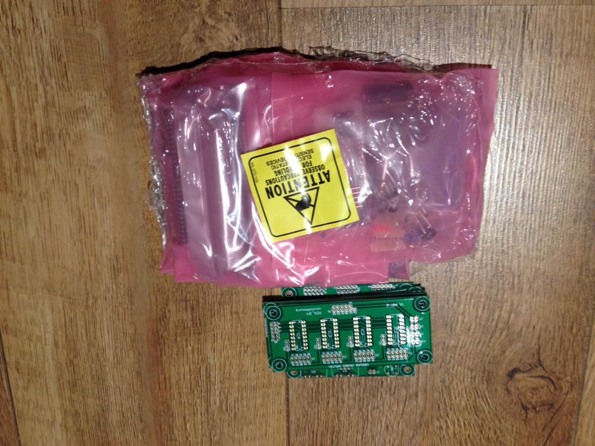
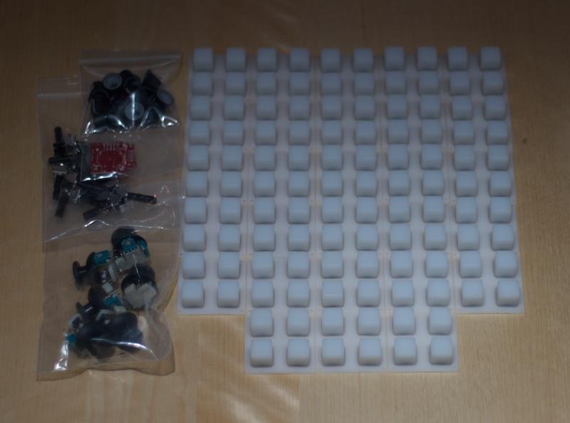
Here's whats available (all bare PCBs come with the parts to build them):
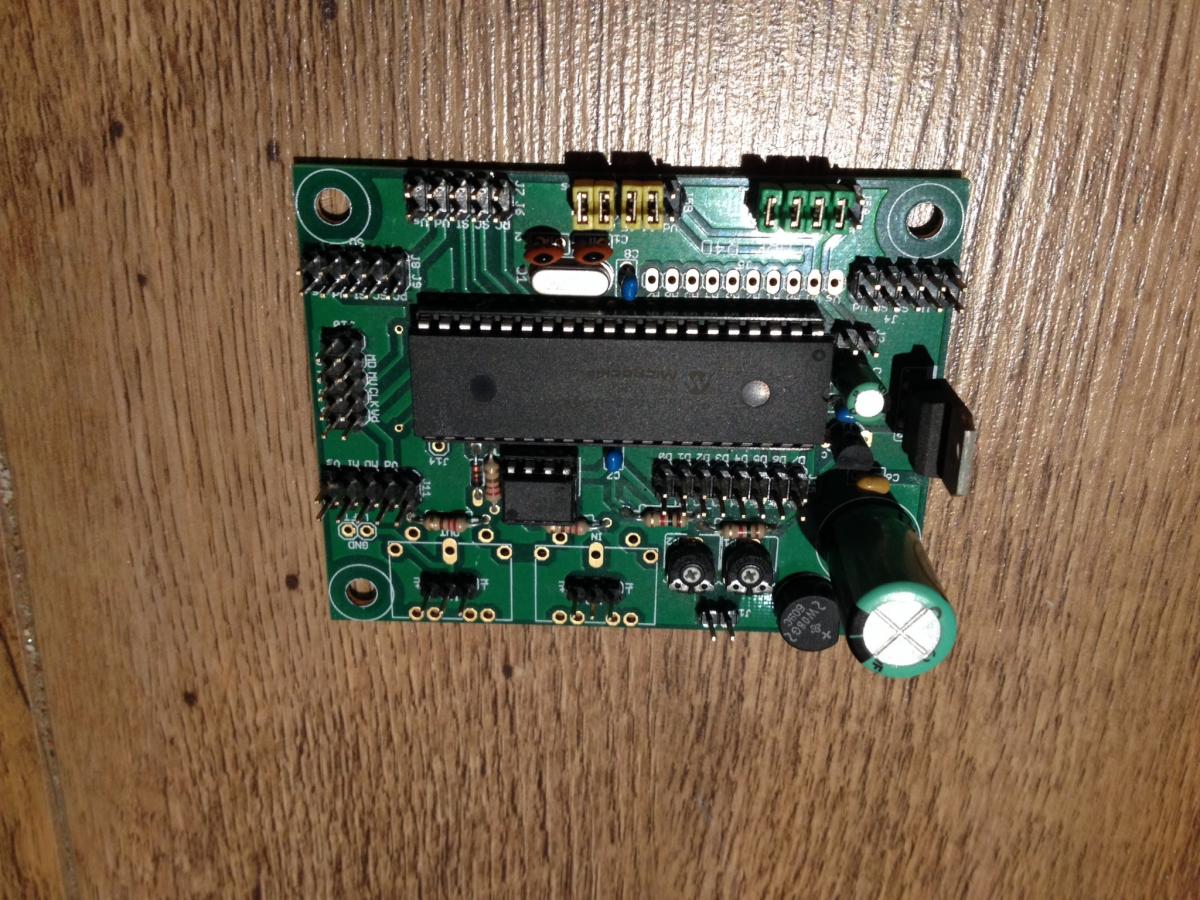
3xcore (2 built, 1 bare)
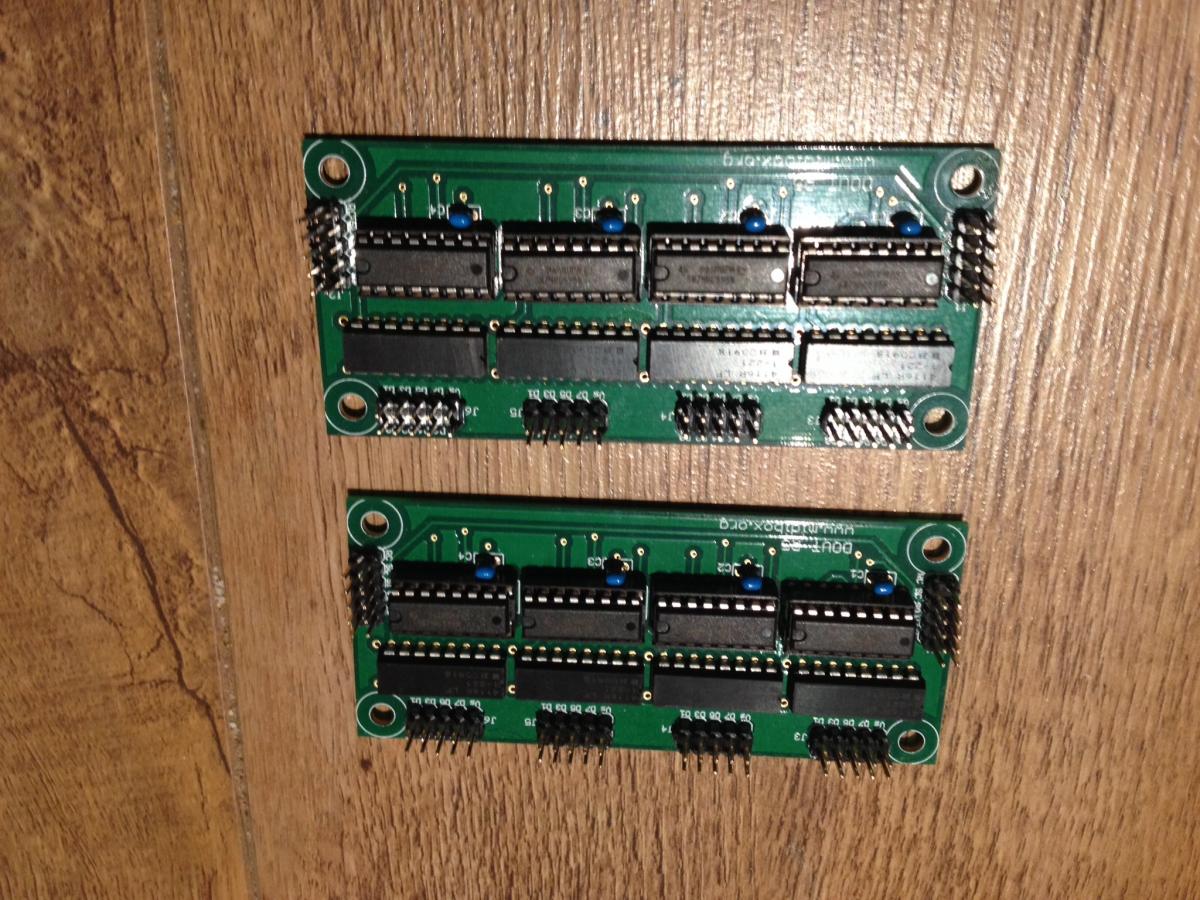
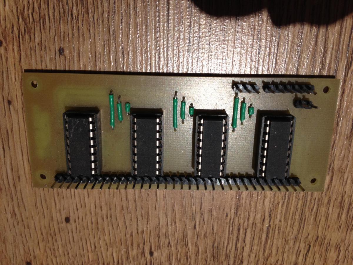
6xDOUT (2 built, 2 bare, 2 resistors added)
4xAIN (2 built, 2 bare)
6xDIN (4 built, 2 bare)
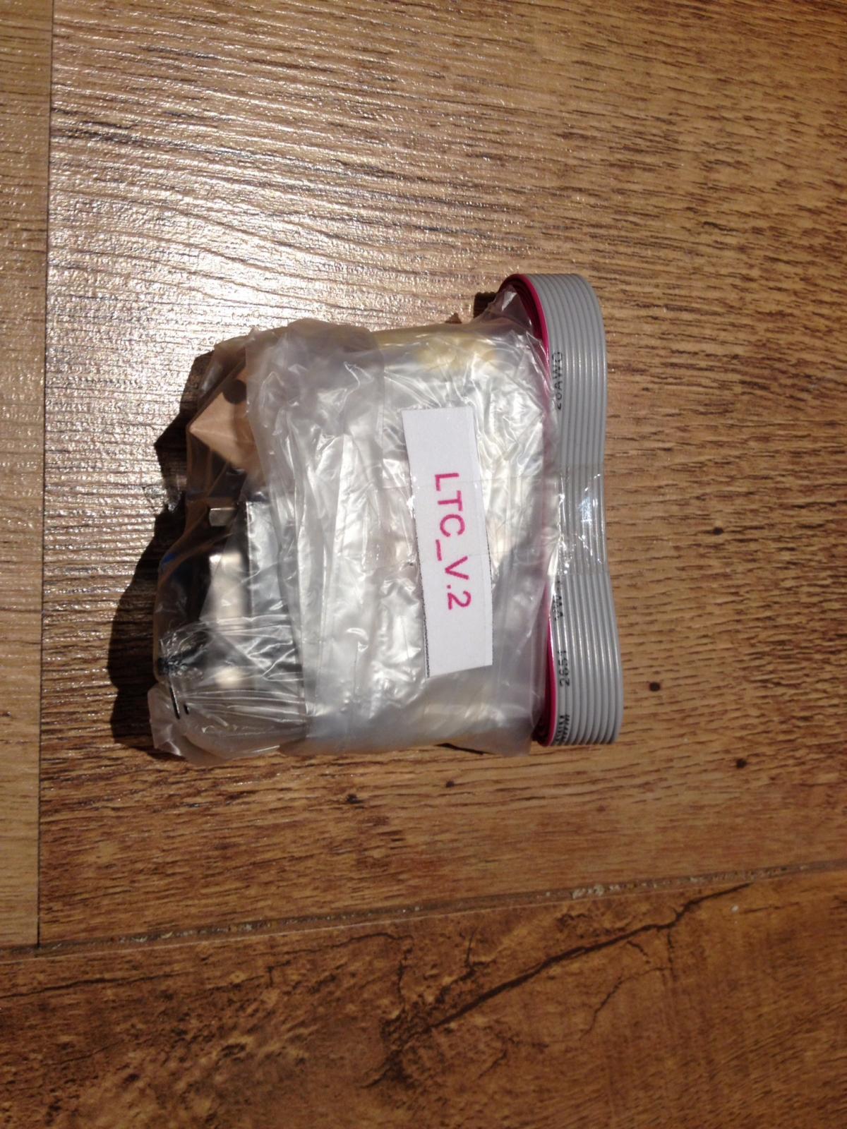
2xLTC (bare)
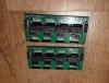
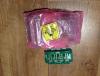
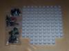
28x Sparkfun button pads (x4 buttons on each)
6x Sparkfun thumb joysticks+boards
14x Knobs
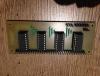
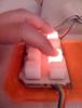
14x Pots A number of orange LEDs Some custom made button boards with LEDs in the center of the buttons. There's three 2x4s and one 3x4(I have the pattern if you want it).
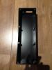
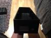
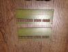
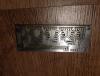
2xCNC'd aluminium cases (I can give you more info on these if interested, but they'll take approx a core, USB driver, IEC port with switch, 2xDOUTs, 2xAINs, 2xDINs etc)
-
Sorry, reviving an old thread. These are all still available, I'd like to sell as one bundle if possible, pm me offers and I'll take the highest one. If no-one is interested in the lot by next weekend I'll start to split it up.
I thought I might get some free time to start up this project again, but man do kids take up your time!!!
Hopefully someone will be able to make something awesome from it!
-
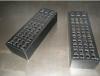
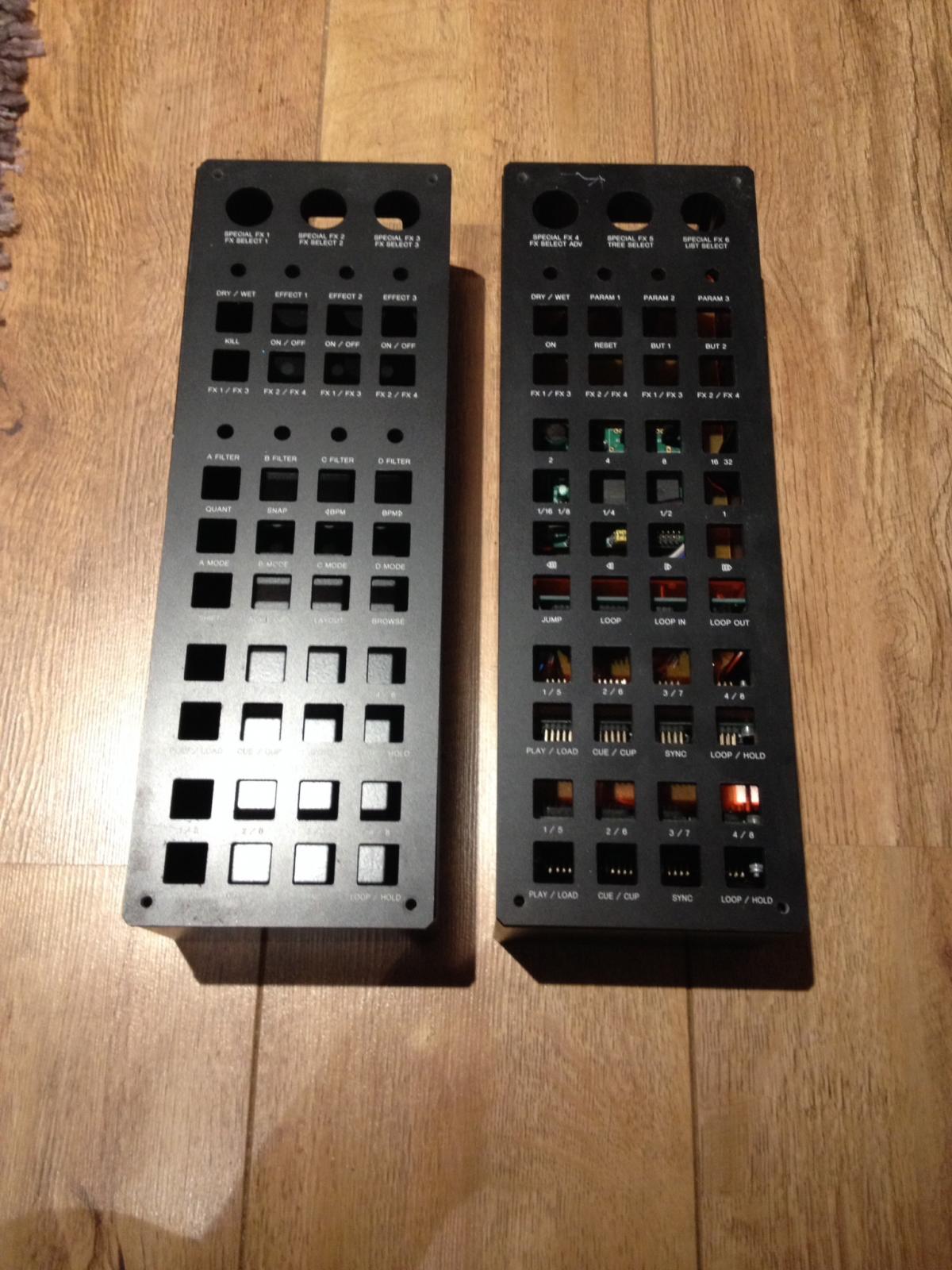
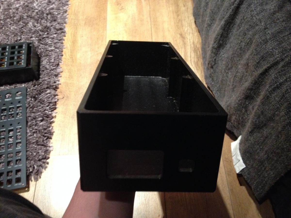
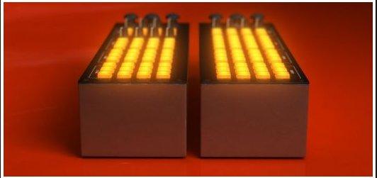
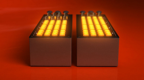
From a project I never finished. 2x enclosures, cnc'd from a block of aluminium that were designed to take the boards you see in the photos, plus a USB driver (GM5) and Power Supply. Holes are the back are for fused IEC port (kettle lead) and USB.
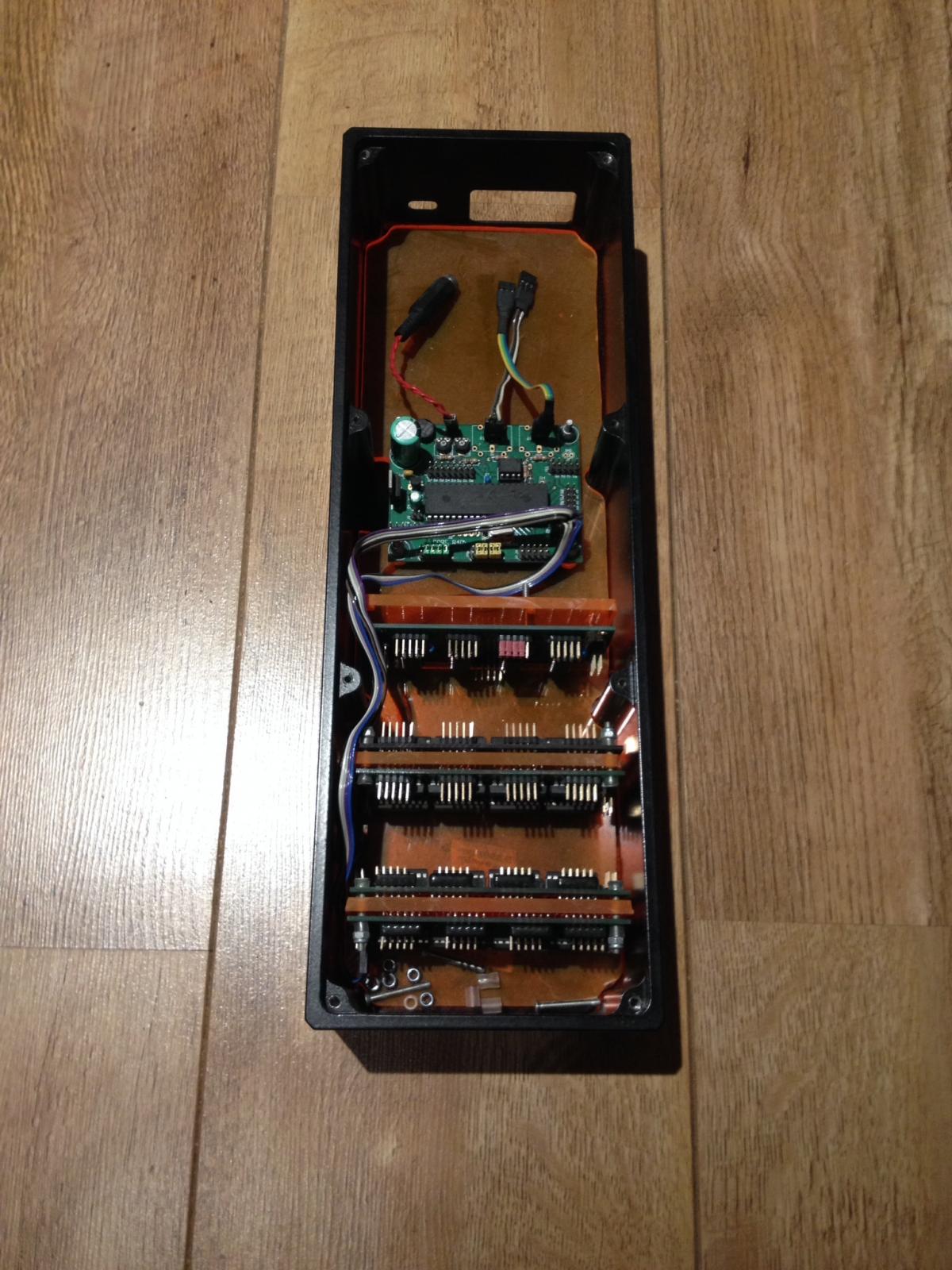
You can have the perspex top if you want, but I'm sure someone will find use for the enclosure with a custom faceplate.
Open to offers.
Thanks
Christian ( Location = Uk )
-
Still up for sale. £45 inc p&p to EU or nearest offer.
-
I never managed to finish my project and now after having a baby won't find the time to do it, so I'm selling the parts. To my knowledge all boards are in working order, however I will take refunds for any board that is not. I have 3 sets in total. One set is still packaged up and untouched.
Sent me a PM with an offer for anything you fancy or any questions.
Thanks
Christian ( Location == Uk)


-
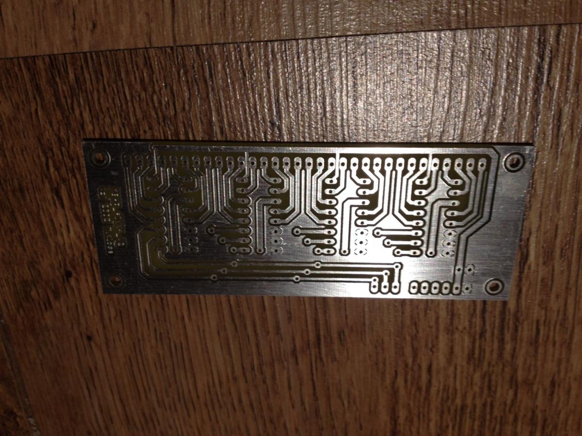
You can see the circuit boards here:
http://www.monstamusic.co.uk/2010/06/how-to-diy-pcbs/
Due to me having a newborn in the house I can't really make any new boards, but can provide you with the file I used.
-
https://www.sparkfun.com/products/7836
You'll probably have to create your own board for 8x3 but the buttons cut up easy enough.
I've got some 3x4 boards from this project.
-
Which ones, the button boards? Cause it's all run of a MidiBox64.
The button/pot boards I'd imagine would work fine as they're just simple circuits.
-
Starting to split, so last chance if anyone is interested.
-
I have a load of buttons, knobs and thumbsticks available.
Open to offers.
-
Make me a sensible offer and it's yours.
-
I'm going to split this into components if no-one is interested in taking the whole project.
-
I have an unfinished (yet all parts there) midibox for sale. The project can be viewed here:
I have two CNC'd boxes with faceplates, all the components and hardware to finish the boxes up.
Let me know if anyone is interested.
Thanks
Christian

-
Cool Blog, MONSTA! I definately enjoy it. Is that Wordpress?
/me likey
Thanks Phunk,
Yeah it's wordpress, based on a theme from Smashing Magazine. I just left all the backend code as it was and re-did the interface.
-
Moved from "MIDIbox HUIs". That was kinda the wrong forum, eh? :tongue:
I guess Miscellaneous was probably a better bet!
-
I was thinking there must be quite a few bloggers here and I usually find it really exciting/informative to see other peoples projects etc...
So if you're interested in setting up a MidiBox blogroll, add your links here.
Monsta
-
Wicked, thanks man!
Ok so my old board should be ok then, which means I can just switch the Vs/Vd around as I please.
I guess I'd want the voltage to increase as I turn the knob Clockwise, but I'm presuming I can just invert this in software anyway.
I'll get it all etch up tomorrow!
Cheers
Monsta
-
Hey everyone,
I'm etching some boards for my project and wondered if I could chain pots like this:

I originally made this board double sided so I didn't have to chain them together, but this would be much better for me if it works.
On a related note, I have these pots from sparkfun, if you face them towards you with the pins at the top, am I correct in saying that Vd is on the left and Vs on the right (to fit the board above)?
Thanks for any help
Monsta
P.s. I have created an instructable on how to make double sided PCBs at home if anyone is interested:
-
Ok thanks TK, as usual!
Adding those two lines to my bash_profile worked perfectly. I haven't tested the result on the Core/GM5 yet, hopefully I'll get the chance tonight/tomorrow, but the "make" works fine now.
Monsta
-
Thanks Thorsten,
I'll check that out tonight.
Monsta
-
Hey everyone. I have a fully working Core with GM5, but I'd like to swap the GM5 to EEPROM mode so I can name the Midi Device and change it's I/Os to 1 (I know I can do this physically, but I'm going to be using two GM5's so want them named properly as well).
I've installed GPUTILS and SDCC which both seem to be installed properly, but when I download the SVN of mbhp_usb_gm5_eeprom and try to run "make" in terminal, I get this error:
Makefile:28: /include/makefile/common.mk: No such file or directory

Makefile:31: /modules/app_lcd/dummy/app_lcd.mk: No such file or directory

Makefile:34: /modules/iic_eeprom8/iic_eeprom8.mk: No such file or directory

make: *** No rule to make target `/modules/iic_eeprom8/iic_eeprom8.mk'.  Stop.
Is the SVN thats up correct, or is my install borked?
Thanks for any help Peeps
Monsta
-
Ok, thanks guys, I hadn't really anticipated this. I guess I looked at the akai thing and read a few half related posts on here and jumped to conclusions.
So I can test with a wallwart I have now, which i have used for testing a different core in the past. But idealy I'd just want to have an iec/kettle plug port on the back that'll connect straight into a psu then into the j1 etc.
Can I build one up based on that c64 optimised schematic I've seen around?
-
With a gm5 and a core + some peripheral (there's going to be more than just the core, right?) you'll easily get over the max. current a USB port can deliver. And that can do anything from simply not work to blow up your maiboard.
Hey guys,
Nils, no I don't know what I'm doing :) I've managed to wing most of my electronics projects, but I'm not a circuits genius by any means!
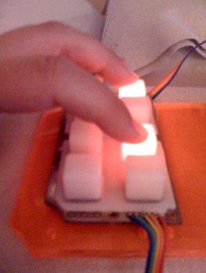
I can't believe you can't power everything off the gm5! I did my research and people were saying that as long as you weren't using LCD's etc it would be fine. Take a look at the attached image to see what I'm building, there is a CORE, 2xDOUT, 2xDIN and 1xAIN in each one + the GM5.
I guess it's not really a massive issue having to use an external power source (there's no room to build one inside), but is this definate that what I'm trying to do with the GM5 is completly misguided and not going to work?
Thanks
Monsta

-
Hey everyone,
I bought an entire Midibox64 kit from smashTV, built it up and tried testing the voltage of the core with a GM5 supplying the power and I'm only getting 1.4v (the GM5 is ouputting about 5v).
With my first kit from Mikes Midi Shop I had exactly the same problem, but could get around this by going straight from the GM5 to J2 on the core. The SmashTV core however doesn't have the J2 pins, anyone have any idea how I can get this all connected up?
Thanks for any help.
Monsta


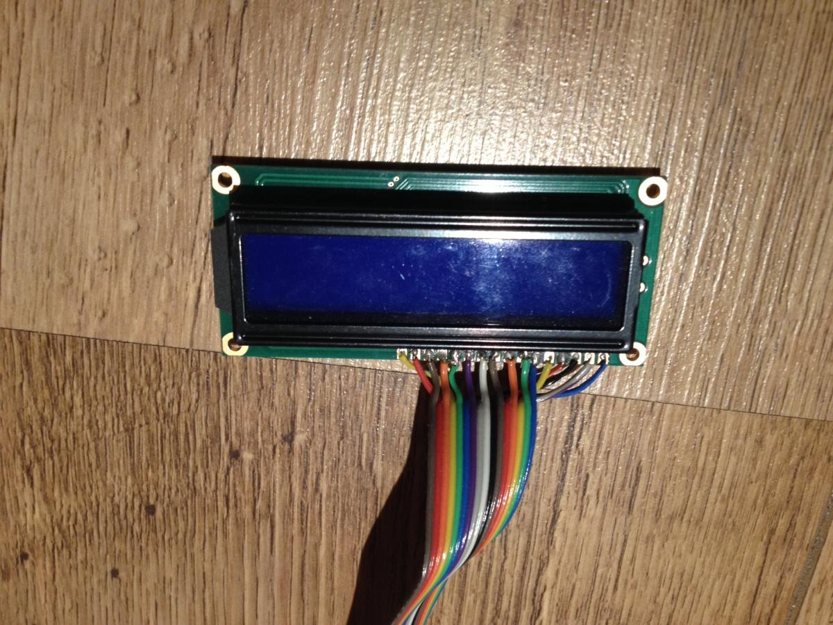

MidiBox Boards - Some complete, others as untouched.
in Fleamarket
Posted
Here's some extra images of everything.