mikee
-
Posts
84 -
Joined
-
Last visited
Content Type
Profiles
Forums
Blogs
Gallery
Everything posted by mikee
-
does old midibox64 retain midi merger enable setting?
mikee replied to mikee's topic in MIDIbox HUIs
Thanks for the info TK, it is appreciated. After construction I found that the merger is already on, so that was cool. The big problem seems to be that system FE commands (active sensing) prevent proper merger operation. I built your filter, modified it to ignore system commands, and all is well in the world. Thank you for all your hard work. regards. -
Greetings Forum members. I wonder if there is a definitive explanation for the above title message? It seems to occour under various situations, but what is it actually intended for? 'Time out' implies some acknowledgement not being recieved after a transmission of midi data, but many midiboxes work quite happily with just a MIDI out connected. No messages pop up. I came across the 'time out' message when trying to use the merge option in a MB64, and the same occoured when I tried using a midi merger (both circuits and firmware belonging to the MBHB stable). It seems to occour when an input contains 'active sense' MIDI messages. But I have not found any reference to this in the archives. It happens that the source code comes with the midi merger (midimerger_v1_5), and after reading through it to see under what circumstances the message 'MIDI Time Out! What's up ???' is invoked, I am surprised to find no such message within the code. There are some references to some locations which begin with "MIDI_TIMEOUT_........" but none shed any light on the missing message. Does anyone understand what the message means? Has anyone got information on how the message is missing in the source, but is obviously in the hex file? Is this perhaps a copyright thing of TK's? Any assistance in this matter would be gratefully recieved. regards
-
MB64 internal midi merger seems not to work.
mikee replied to mikee's topic in Testing/Troubleshooting
Further to my first post: I have just programmed a pic16f88 and built the old midimerger with these results: midi data from the core is being processed by the new merger, but data from my keyboard still fails to appear at the output. The led indicator for that particular input fails to light at all, the indicator for the input from my core blinks quite happily. In other words all is just like when using the core internal merger. I have tried different values of pullups to drive the input (including 1K2 ohms) although it must be said: the value of 510 ohms suits my sound card perfectly. -
Hello all forum friends. I hope someone can give a helping hand with a little problem of mine: First I connect my core MIDI out (pin 25 TX) to my soundcard MIDI in. Next I connect one pot and (giving a swift twiddle) note that the correct midi signal appears via midiox. Then I set the internal core midimerger to 'ON' via the three menu buttons. Next, I connect a good known working opto coupler (same circuit as MB64 core) to pin 26 (RX) of the core chip. Finally, I plug a good keyboard into the opto circuit expecting to see note data via midiox. But do I? Not on your nellie. As soon as I power up my keyboard midiox says: status; 178, data 1; 0, data 2, 0, channel, 3, event, CC: Bank MSB. Then the midibox display says "Midi time out, Whats up?" A question I would dearly love to find the answer to. I know the core chip recieves MIDI from my keyboard (via the same opto coupler set up), and I know the core is sending MIDI signals whenever the pot is turned, I also know the same keyboard/opto circuit happily drives the MIDI input of my sound card. Why won't the core merger let me merge stuff? Does anyone have a system with the internal merger working? It might be of some importance to note that my keyboard sends continuous MIDI 'active sense' messages. Thanks for any possible comments in advance.
-
Hi all. Does anyone know how on earth one is supposed to turn the midi merger on? What buttons are used? Is button 4 both a snapshot and 'enter' button? As per title, if I manage to set the midi merger to on, is it meant to retain the new setting when powered down? thanks in advance for any advice. Regards to all
-
Thanks TK, your interest is truly appreciated. That link is excellent, as it answers all my questions re MIDI. You said " MIDI Timeout: could happen if there is a problem with the optocoupler circuit - it could be, that your MIDI IN isn't working yet?" I think you are correct. I have not yet fitted an Optocoupler circuit, and I imagine the Midibox is looking for a reply to some code. I will get that sorted out very soon. But I need a few buttons for Menu and perhaps a few triggers, so I am just in the middle of stuffing some strip board with a couple of chips. Soon as that's done and tested I shall connect the MIDI I/O correctly, and see what happens. The Midibox output drives the MIDI in of my old Soundblaster card, and all tests are good in that direction. Best regards
-
Thanks again TK. I had clamped all 8 analog inputs to the wiper of a 10K pot (the other ends to +5V and 0V of course) so no pick-up problems there. The trouble was indeed in the configuration. In fact, although the config is held in the HEX file, my programmer still requires it to be manually entered, without this, the programmer sets the config as external RC oscillator, therefore no go Joe. (Thanks also for that link). I suspected that the MIDI merge has to be switched on, but is it achieved via the panel buttons, or by sysex? I do hope it's a simple matter of menu selecting, and not sysex. Anyway, I have the whole thing up and running, and having found some old chips so am now knocking up a board to read 32 pots and 16 buttons. As a matter of interest > this seems not to affect the controller's functions, as it sends MIDI CC messages fine < but I noticed that when the thing is first switched on, the display says 'MIDI TIMEOUT' . I wonder is this something to do with Sysex? Regards
-
Just had another look: I never set the config bits! Forgot that they are not part of the hex file (or so it seems). Anyway, programmed pic ok, stuck it in circuit but display (although lit up) was blank. Hmm. Tacked two wires to a piezo sounder, and placed across MIDI out pin of chip: lots of activity heard: seems ok. My newly soldered contrast pot (both contrast pot and brightness are both soldered to the actual display - not the core module) needed setting. The only decent 10K pot was a little square multiturn - wasteful but it works. Now I have lift off. Next thing: if I connect my MIDI keyboard to core module, do I need to tell the program to merge it with the main stream?. . or is it done auto?
-
Thanks to TK. Yes, I built the thing last night (20 Mhz crystal) and I even threw an LCD display in, then I unzipped the firmware (midibox64_v101b_mbhp.hex) and tried to burn it into a virgin PIC16F877, but alas, the software I am using (Piklab on Linux) - although perfectly good when it comes to its assember- refuses to write hex files. So I wondered if anyone knows of a simple (Linux) method of stuffing the chip with hex? The last time I did all this I used MPlab under Windows, and to be honest, I had no problems - the obvious solution I suppose is to revert to Windows etc.
-
Hi Janis and thanks for the input and effort, I appreciate it. It seems that you have found the page I have been searching for. I used to have all the original info when Midibox was quite new, but things easily go adrift in the sea of info. It seems certain that the schematic for V3 is pin compatable with my old chips, so I had better get my old burner out and try remembering it all again. Thanks again, and to anyone else who looked in. This topic is satisfied.
-
Thanks for the interest digineural. I must have been thinking of the Midibox64 V1, which was based on the PIC16F877, but I now recall V3 was far better to work with. I have some PIC16F877's burned with Midibox64_v101b_mbhp.hex firmware, so I thought I would knock some MIDI stuff together. regards to you
-
hi there you mad mad Midiboxers. This is a rather silly request, but I need the schematic of the old non-mios Midibox64 core module. It used the old PIC16F877. I cannot locate my copy and it is no longer published by uCApps. Does anyone have a copy? Does anyone know of where it might be archived? Thanks in advance for any help in this matter.
-
-------------------------------------------------------------------------------------------- Thank you very much for that info Thorsten. I certainly appreciate it. In passing (if you happen to have a spare moment) I was wondering: does the Midi merger function (non-Mios software such as old midibox 64 etc) default to merger ON or OFF? very best regards to you.
-
Thanks for that. I will attempt to install said Studio. best regards.
-
Hi forum, I cannot find anywhere to put this topic (apart from the obvious) so please excuse. I have lots of chips: PIC16F877. mmmm m, I love these little chippy chappies. I have the hex file for Midibox plus (16 pots). Question: what must the CONFIG header (fuses) be set to in my programmer? It being a hex file I don't know what the CONFIG should be, apart from high speed crystal. I know its an old chip, I know Midibox plus is not MIOS based, I know everyones into big-ram chips, but all I need is to burn the darn thing with the darn hex file. If anyone can advise I would certainly appreciate their input. best regards to all
-
Thanks for the quick reply. Yes I have seen it (mios32_toolchain) and tried without success to build the thing, unfortunately it fails. (comes up with the message: make: arm-none-eabi-gcc: Command not found, although I entered MIOS32_GCC_PREFIX=arm-none-eabi.) I would have loaded an old pc with Windows XP (this works fine with Studio) but the disk got lost some time ago, and I am stuck with everything Linux. It has been some time since I played around with MB and I cannot recall how I got the thing running after burning in the boot loader. Thanks again.
-
Hello MB forum friends. I intend to construct a Midibox64 project using a PIC18F452. I only need 8 pots to start (expand later), MIDI in/out, but absolutely nothing else. I have a programmer. I use Linux, not Windows. Hardware questions aside, I seek the following info: After I burn in "bootloader_v1_2_pic18f452.hex", what is the simplest way to upload the hex file MIOS V1.9g via MIDI? Can this process only be achieved with MIOS Studio, or is there another way? Note: Both the bootloader and MJIOS hex files come from out of mios_v1_9g.zip. Thanks in advance for any help which might be offered. Regards
-
No. If by input transformer you mean mains power transformer, then also no. It comes with +5V dc SMPSU with output current capability sufficient to supply Mindibox. thanks for interest.
-
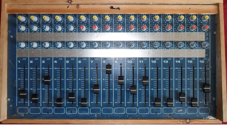
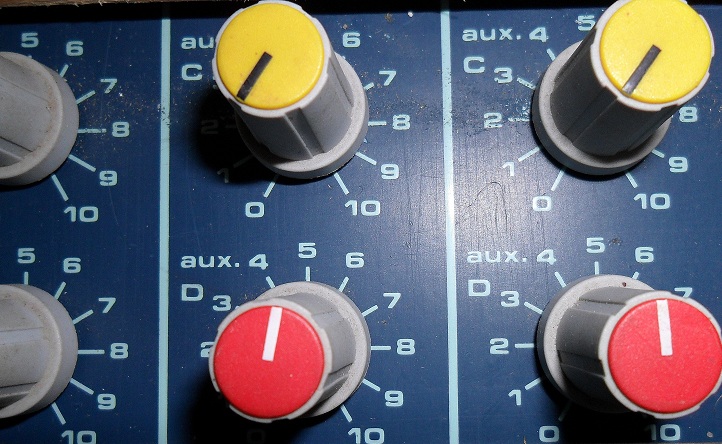
Hello MB fans Here are some things for sale. I am not asking the earth. just a fair price. All the parts for an excellent Midibox 64 channel Controller This unit was first tested using veroboard rather than the commercial printed circuit boards, thus everything was contained on one board. The unit functioned perfectly, and was used to drive various software midi-controllers including FL Studio and Ablaton Live. It was intended to rebuild onto a much smaller circuit board, but the work was interrupted by illness. The result is the following quality parts. All the purchaser need do is provide whatever boards they wish, and put the chips in. A power supply is also included, and support in the re-construction is offered via email if required. * Control panel set into sloping wooden housing. 70 x 32 x (5 slopes down to 3 cm) Pre-wired fitted with 64 pots: * 48 rotary pots * 16 slider pots 10cm (4 inch) length (These are professional mixer desk size) * Professional knobs. * 5v power supply. Connections: Positive to top pot rail and negative (Ov) to bottom pot rail. * Comes with 8 integrated circuits: 8 channel analog mux chips for 64 analog channels. 8 DOUT chips and 8 DIN chips. * PIC18F452 pre-programmed with MIOS V1.9F BOOTLOADER V1.2B. Easily re-programmed. (See below for parallel port programmer) * HY1602A LCD display (internal light) inc front mounting bezel, * Will throw in the programmer which burns both the PIC18F245 and the smaller (12 bit) PIC. (ref MIDIbox Hardware Platform, PIC Burner/Brenner driver etc) Note: although the DOUT circuits, like everything else, worked very well (driving leds on/off to indicate DIN switch conditions) I found that they were really not needed for my application, as the pc screen gave sufficent info. The DIN circuits, having tested perfect, were also not required. Even the LCD display was not really required, thus the project ended up with just 64 MIDI controller pots. How much? the first to make guenuine offer of £50 gets all the stuff. (please note : add £15.50 to cover p & p unless you can collect in person.) email: theminde[at]btinternet.com


-
Yes indoodlydeedly. Often the simpler solutions work better. good burning
-
Sorry bout that friends, app = ain64_din128_dout128_v1_3 hardware = full compliment pots, switches and leds, 5V/3A lin reg, standard two line LCD etc etc ..... chips etc built on single piece of plain perf board. I don't assume any fault folks, as all is fine. Its juat that I expected to see MIDI activity on the display without connecting box to MIDI-games port. MIDI non connect: Apply power to app. LCD shows only the standard (undriven) blocks of graphics. MIDI connect: Apply power to app. LCD displays names name then AIN, DIN DOUT etc. regards all
-
Hi all ref attatched diagrams: The first (original) is original circuit (schematic) of the LCD backlight brightness control. Second (modified) looks better to me, and works very well too ;) regards all lcd bright.JPG lcd bright.JPG
-
hi all I cannot find this effect listed elsewhere, but it might be of some help to someone, especially when first testing: No messages will be displayed on the LCD if the MIDI connections are not made to the pc. It seems that the software waits for a response from your pc during initilization. Perhaps someone else might expand. regards all
-
casio keyboard parts, hammond pedals and a lamp driven from midi? where's the midibox stuff? Are you simply trying to make a lamp flash on and off when a pedal is pressed? that only requires a 12v 2.5w car lamp (Halfords or any car parts shop) a couple of transistors, and a few bits n pieces. The midi output (before the opto isolator) will drive the thing. See attatchment (The transistors are not critical, as long as they are NPN.) regards oops, just realised--- MIDI too fast, lamp too slow. You really need to stretch the MIDI pulses, perhaps a 555 timer or something. If all else fails get youself a pet monkey and train it to flash a torch as you pedal away. regards again. midi_lamp_flasher.JPG midi_lamp_flasher.JPG
-
bypass capacitor, long cable and switchmode PSU
mikee replied to protofuse's topic in Design Concepts
I assume you are presently using a switched mode psu: I am interested as to why do you consider linear psu to be safer? regards