tonyn
-
Posts
203 -
Joined
-
Last visited
Content Type
Profiles
Forums
Blogs
Gallery
Everything posted by tonyn
-
Sheu.. I finished wiring up the Accompanment baord last night as planned. It isn't hard, just tedious and takes time. Before I put the ICs in I electrically tested the Power adaptor, the dins, and core for voltages, etc. I tested these because I hadn't. for the Solo I did no electrical tests since the dins core and power adpator were already tested for the push button board. Then inserted the ICs, installed in organ, connected to computer and it worked. So I setup midibox128, reconfigured for channel 2 for this keyboard. But I had no keypresses! I tested for continuity with the contacts, etc. Then I decided to check out each din to the core. So I made a long IDC cable for testing. Connected from core to second din. Wahla I had keypresses. Connected from core to first din and the same. Put cable between dins back and used test cable from core to first din and everythign worked. My IDC cable from the core to the first din was bad. I also foudn that on this baord I did not have to move the cable between the dins to the right (I wanted to figure that one out). So the Solo baord's cable between the disn is bad, now I knwo. It's a good thing I have spare IDC connectors and enough cable. Now I need to adjust a few of the key hammers some and add some felt pieces to the ones that they came off of. Those felt pieces quiet the hammers when they hit the tabs, and also keep them from slipping off of the tabs. So it's important to have them all on. I think I'll try contact cemment to reattach them.

-
I just thought of a neat idea! Since I am going to make my own stop tabs with colored acrylic; to name the stop tabs without etching or putting a label on them: I could put tiny LCDs behind them that are programable! Then LEDs behind them to light them up. When I was at American Science and Surplus there were a ton of tiny LCDs in a bin! I would run them off of a separate microcontroller board. I do have some microcontroller baords to play with for this. They have a USB interface to program them. So I could write programs to change the names on the fly of the stop tabs and different instruments, etc. Neat eh? I'll prototype this out to see how it would work first. This way on the comptuer with custom programs: Change virtual organ console, it will upload a new program to the microcontroller which changes the names of the stops accordingly! I'll be taking advanced Java programming this next semester, so this is something I can work on in Java too to integrate with Jorgan, etc. Acually instead of uploading new code to a microcontroller, I could have push buttons that the controller detects to change routines in code to change names, etc. There could be a scroll up and a scroll down buttons to scroll more stop tabs than physically installed! But that would also require and update to midibox too, etc. Or do I hear "core 32 calling"? Well I'll play with this after I finish the pedal board and swell. Just ideas... I need to start thinking out the stop tabs, since tonight I will finish the Accompanment, and basically have the keyboards all done(until I add first touch, second is first right now, but this will be much later). Within the next couple of weeks I should have the pedal board and swell done. Then it's onto the stops and pistons(the pistons are easy)!
-
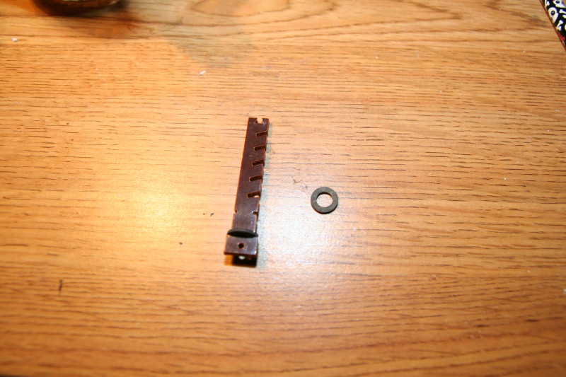
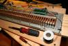
OK. I just replaced the top 4 tabs of the Solo keyboard. So now all keys play except for the lowest C, which needs a tab that I will dremel out for it. I was able to replace those tabs without removing the Solo board from the organ. It was tricky though and I had to remove the nuts and lock washers to lift it up slightly to insert from the bottom. The Accompanment I will do outside of the organ where I am working on it anyway wiring up the dins. A few tricks on these tabs you may want to know: Be careful of the top notch where the leaf spring gos into. If you remove or insert it wrong you can break the top notch. You tilt the leaf spring into the notch on one side and lower or lift it from the other. Also the rubber gromets need to be worked down the tab. Be careful with those too since over the years the rubber can dry out and they may tear. I had no problems, just wanted to pass this along. Here's a close-up picture of a tab and rubber gromet so you can see what I am talking about. The 2 bottom notches are for the gromets. The bottom one stops the tab from going up too far, and is inserted first. Then the tab gos into the the board, and the second from the bottom notch is for the second gromet which you work down the tab being careful on the notched side. On top is a trangular notch for the leaf spring. The other notches are for the contact spring wires. I use the bottom 2.

-
Just got back from my organ guy. He had ALL of the tabs I needed except the 6 layer one for the Solo. But he gave me a few extra longer ones and after we looked at them, I can use a dremel tool to cut a long one down to make a shorter one. While I was there we talked about how my organ was designed, etc. Yes, those contact boards with the preinstalled wires were for the percusion and had high voltage to them. The pedal boards have the same type of contact boards, etc. So that should be easy to do the same design with them. Except that I do not want the Dins and core down under the organ, so I will run wires up from the contact boards to where I will mount the dins and core. But, since the contact baords are the same, according to him, that means I could also do second touch for the pedals too! So I'll need to plan on another din! My midified Baldwin will have features that were not in the origional! He also said that the motor controller design of the leslie for my Baldwin was the good design! There are 2 motor controllers and 2 motors. One for slow speed and the second for fast. These are controlled by 1 stop(a 3rd stop turns the leslie motors on/off) So I now know what I need to control them. He will get me the schematic too so I can put back those motor speed control drivers. I also stopped by that organ store that had that Modernized lowery organ that inspried me to do this. That organ sells for $35,000! It has more stops and fuctions than you can count! It also has 16 speakers! At least that is what he said. I can't imagine how they cramed and why that many speakers in. It has a nice wrap around cherry console, but only 2 keyboards(I don't peticularly like the lowery keys, mine are sharp, their's are square), and a 25 pedal pedal board(short pedals, mine are full sized). That organ was origionally in the Pabst Theater. He said they are thinking of buying it back, unless someone else buys it first. Not me, that is too much! I am only looking at it for ideas. It has all push button type stop tabs with LEDs, that is what I need/want. My organ guy knows and will be looking at what he can get for me. He said I could buy them new too, but they may add up like my push buttons(122 for $130). I expect the stop types to be a lot more new! But they are also etched with the names of the instruments, etc. So I may have to order what I want, new. But I won't have the money for that part until Febuary anyway. Plus my organ guy will be looking for them too for me. He gets trades and parts from older organs in all of the time. He said who knows what he may have by Febuary. Who knows I may also design my own too! I already have 122 push buttons. All I need to do is design nice colored acrylic covers and put LEDs behind them. Damn! That's what I'll do! This way I can customize the stop tabs to replace, exactly, the old stop tabs and even use the old stop board! I found where they put the DVD drive and front panel card reader/USB, so that is where I will put those on my organ too. But it only has a 4x5 inch touch screen. I have a 15 inch! But I need to figure out how to mount mine so it is out of the way, but can move to where you want it. Right now it's on a cheap arm. Later I will get a better arm, etc. I also have to figure out where to put my keyboard and mouse, so they are out of the way, but accessable when needed. My computer power supply and guts will be mounted in the top part of the organ. I have ideas on where to put them too. Here is something that I also figured out: Powering off the computer from the main of the organ power switch? You DO NOT WANT TO JUST TURN OFF YOU COMPUTER, ESPESCIALLY IF IT'S RUNNING WINDOWS. Simple: I will install a UPS battery backup power strip (actually I will gut one I have and use the circuit board and battery, and wire up my own outlets, etc.) in the organ for the computer and electronics. This power strip will be powered on/off by the organ's main power switch. The UPS will have a plug as most do, that the computer can detect loss of power to the UPS with, and properly shut down the computer. Wahla! One power switch controls all! Plus a UPS is good to use even if you do not use the battery backup part, since it conditions line voltage too for sensitive electronics. The UPS strip will also be mounted inside of the organ. This is why it is important to me to design the midi circuits to not take up any additional organ space. I will need all I can use for this stuff too.
-
Good new guys! My organ guy has ALL of the tabs I need except 3 from the Solo! But those I can see about repairing, or he can check into orderin them from Baldwin. He is giving them to me free, since I did some comptuer work for him. I just need to pick them up. This will give me all keys except 3 on the upper end of the Solo. I also got my order for my spare optocoupler ICs in today and will be picking them up too.
-
For those of you whom are following me and want to copy me with your Baldwin 210, etc., that is the same: If you are wondering how I got perfect hole alignments for my plexiglass boards: Don't forget you have spare contact circuit boards to use as templates! 2 are wider and the other 8 are smaller. Take a same size contact board, align the plexiglass piece of the same size with the buss metal of the contact board(my plexiglass pieces go just to the metal of the buss of the contact boards), and tape it on top of one of the pelxiglass pieces, put a marker through the holes to mark where the holes go onto the plexiglass. Take a small drill bit (plexiglass is slippery, so you can do it better with a pilot hole first) I used a small bit with my dremel tool. Drill a pilot hole, and then a drill bit for # 6 through holes (the screws that go through them are 4mm, but the #6 trough hole bit allows for a bit of play, which you want) I don't know what the size of the #6 through hole bit is, but your handy hardware guys does. Then use that piece of plexiglass as a template for the rest. Don't try to drill all of the same plexiglass boards at once, else you may have off holes (it's the thickness of them altogether, that unless you have a drill press, and can get it perfectly streight, the holes will be off). Use the plexiglass templates and tape one plexiglass piece at a time to it. Drill slowly, with little pressure, else you will crack the plexiglass. Now how to align the holes for the dins and core: Mount all of the plexiglass boards onto your contact board. Align the dins and core where you want them, use the marker again(I used bare boards to get them flat on the plexiglass, I had spares to do this with). Mark your holes and also what board gos where(i.e. Solo board 1,2, etc.). This is so you can put them back where they go. I did each board(Solo and Acompanment), separately, so the holes maybe different for each. By having the boards marked, you will know what gos where when you reassemble them. You can drill the small pilot holes while mounted (be careful to not drill through the contact boards under them though). But DO NOT DRILL THE BIGGER HOLES WITH THEM MOUNTED, ELSE YOU MAY DAMAGE THEM. Remove them and drill the bigger holes with the same #6 through hole bit(see it works for both, the screws for the dins and core are #6). Using these tricks I had all of my plexiglass perfect in no time, without a drill press!. I only had one cracked hole because I didn't think to start and pressed too hard while drilling. But everything else turned out perfect, as you saw. If you have any questions on how I did something, feel free to ask. But read my whole thread first, since there is a lot of info in it that I may have already answered.
-
I did notice that a few of the keys on my Solo keyboard were not working where the tabs were good. So I opened the organ and through investigating. 2 just had the contact springs in the wrong slots. No biggy. But 2 on the upper end had to have the key metal bent a bit so they could push the tab all of the way to make good contact. So my wires are JUST right for second touch and make contact at the last part of the keypress. This is the farthest reach of the keys when pressed, so second touch may need a bit of adjusting for. I also found that just a nut in between the contact board mount and the metal of the organ is just right. Even a washer more would be too much, espescially if you want the second touch as I am planning on. This is #8 hardware for the mounting of the contact boards to the organ metal. Now to get back to my organ guy for those broken tab replacements. Plus I need to finish up my Accompanment board too.
-
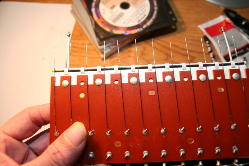
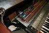
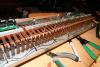
After RVbottomly posted about his Baldwin having silver contacts, and that the percusion didn't have the resistive contact rubber: I decided to check out my boards I found that had a 16 gauges wire installed. I don't know wether it is copper or silver, or what. But it does have a black coating on it. I didn't find these boards until after I had initially found the rubberized boards and came up with the idea of the 18 gauge copper wire. It's nice to know that my thoughts were right on tract with what the Baldwin people thought of too. Except they put the wire in the middle, and I put it on top. But I am working on adding second touch, so I wanted the farthest that the key can go to make contact for second touch. The reasons that I wanted to get second touch first, was that all of the initial adjustments to get the farthest keypress makes for easy first touch to get a closer keypress by just inserting wires to the bottom, or middle, of the boards I want for first touch, wire up a second set of dins to them, and I am there. My wire placement and gauge does work for the farthest keypress as you saw a couple of posts back. Their wire is a little bit thicker than 18 gauge too(I assume 16 gauge, but haven't checked it out). But these boards DO have zero resistance if you clean the wire. Over the years or with high voltages, etc., these contacts on these board have like a carbon residue on them. Or they may have been meant to be resistive and were coated. I don't have the schematic on my organ, yet(I will get one though). But by scrapping the wire a bit I got zero resistance. As you can see this 16 gauge wire is in the middle. Through my tests this would be middle keypress. OK if you want only a one touch keyboard. Plus you would need to clean these boards if yours is like mine for good contacts. I just picked out the best boards with shinny wires and the rubber so I have good contacts, and inserted my 18 gauge instead. There are enough spare boards with the rubber that you can get the sets of 2, like I did, that match, so that you can make one for first touch, and the second for second touch. I still think that I went the right route, since with the 18 gauge you can have one wire on top for second touch and one either in the middle or bottom for first. They could optionally be tinned so the copper doesn't corode over time. The difference will be slight but can fit into the specs, maybe, of first and second touch. I did read somewhere that the specs say first touch and second touch should be 1/8" in difference in keypress. But is that from the top of the press or bottom? Anyone have specs on that? Anyway, here's a picture of a board that has a preinserted wire. As you can see there is carbon on the wires that needs to be cleaned off if you want good contacts.

-
OOPS. Somehow I got a double post. Read my next post...
-
I am just about done with the keyboards guys(until I figure out second touch, much later)! The Accompanment is about the same as the Solo, so it should work fine too. Note: Plexiglass is brittle and can easily crack or fracture under too much preasure. I already knew this, so where I had metal to plexiglass(nuts, lock washrs, etc.), I did not tighten too tight. You have to have a feel for this to get it tight enough but not too tight. I also did not tighten too tight on the circuit boards either since they also can crack, etc. This comes with experience. I have years of it and know about how tight to tighten things. There is also the stress factor: Years of something being a bit too tight will eventually cause problems. This gos for wires, etc. So leave some play. But I am not done yet guys! This thread will grow to huge by the time I am done. I will cover every detail from start to a completely modernized midified computerized organ! I even have some carpentry work to do too. You will see me aproach EVERYTHING as I go. Next on the agenda is the pedal board and swell pedal. I wonder what I will find there? :blink: Don't forget the rest of my thread too. Go back and you may find some interesting thoughts, and trails and errors, that may help you in your thought processes and projects too.
-
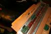
Here's my reconfigured MIDI_OUT part of midibox128.ini file. It has been compiled and uploaded to the core and now the keyboard is completely playable in Miditzer and Jorgan! As you can now see the mapping is in order from the lowest C to the highest C!
-
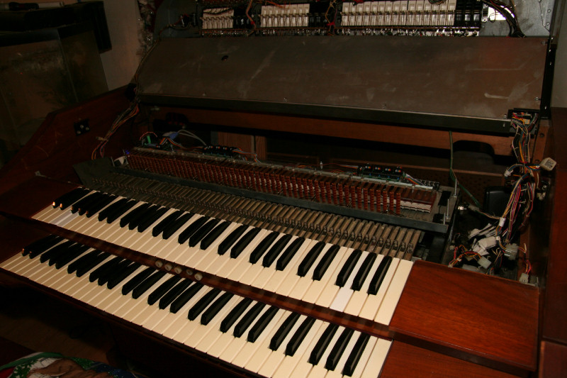
It works beautifully! I didn't have to adjust ANYTHING! The feel is fantastic too, just what I wanted! The keys play notes at just about the bottom of the keypress(tested in midi-ox output monitor) Or so it seems. I'll do better tests later. But hopefully this could be second touch (which the placement of my copper wire would be for the sets of contacts that are active now) But working on first and second touch is for much later... I need specs on first and second touch. Anyone? So soft, no stiffness at all(perfect in fact)! Every key that does not have a broken tab (the broken tabs are removed so that there are no shorts, etc.) plays even in Jorgan! Except they are out of place. I need to remap the keys in midibox. But they are all in good physical order now too(i.e. pin 1 on din 1 is key 1, etc.) for neat organized code! I didn't finish putting the old cover, etc., on the Solo board, just in case I had to remove it to adjust something, etc. But since I made sure everything would fit within the demensions of the old area, I should be able to enclose it easily with the old covers, etc. Now to finish the Accompanment.
-
Yes my organ has percussion. I did find a few contact boards to have 16 gauge wires installed. But they were black, so I thought they were insulated. Some contact boards also had some carbon on the wires, etc. That may have come from high voltage with the old electronics. So I only used contact boards that had nice shinny wire, etc. But those boards with the wire already inserted may have been OK to use. They may have been for the percusion on my organ too. I only pulled out one board to test it to see what I had. So I didn't find those 16 gauge wire boards until I had already had my plans for the copper wire, and got to them(they were buried). By then it was too late anyway, for me. But my wire I have experience with now and maybe able to , by moving it, get 2 areas of a keypress to make contact, etc. The copper wire route seemed to be my only option. If you didn't have any rubber nor wire inserted those contacts may not make contact. Those metal busses are on a 45 degree angle, and with the rubber removed the contact spring wires can't touch the metal. So that was why I had to fill in that space with something conductive. Yours maybe bit different. But this is what I found with mine. Yes, I maybe farther along because I have been at it night and day for the last weeks! But I am going back to school soon and want to get as far as I can before I am heavily in study. I am chugging away at it daily. You can maybe just read my thread to see how I aproach other parts so you can get an idea before you atempt it with your organ too. This thread will grow to cover every bit of this from start to a completely midified organ. I also will be doign some carpentry work to repair the cabinet. so a bit of everything! Next on the agenda is the pedal board and swell pedal. I wonder what I'll find there? I hope you enjoy my long thread. I am trying to provide plenty of pictures so if people have simular organs they can see how it can be done. I am passing along a few tricks I have learned over the years for the unexperienced, so they know how to do it. I am also sharing my thoughts and trials and errors, to help others to avoid them. Feel free to share what you found with your organ too if you want. How far are you, and why are you too late?
-
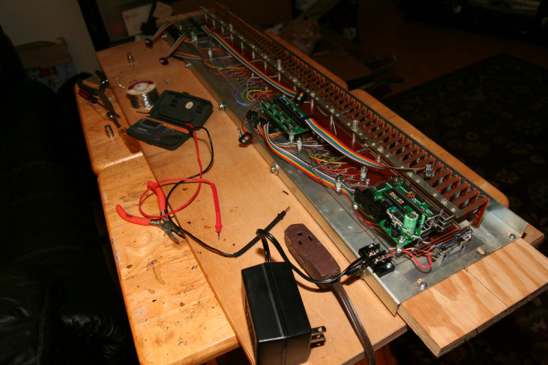
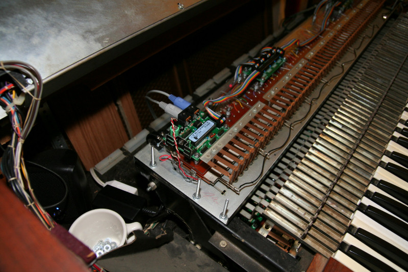
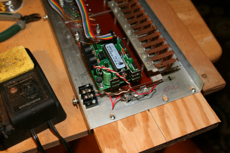
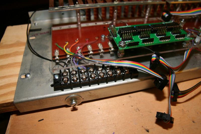
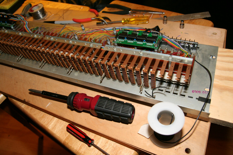
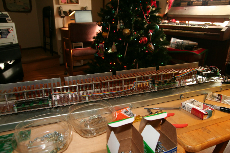
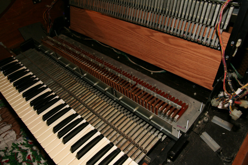
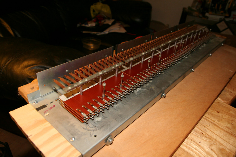
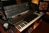
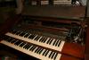
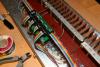
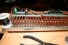
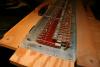
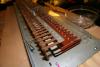
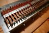
Sheu... I just finished wiring up the Solo board, and have a bunch of pictures for you! As you can see I mounted the power terminal and fuse holder to the metal part for security. Then I cut the lengths of ribbon cable for the longest length to the last point per din and cable. Instead of making all of my cables the same length, I then cut 5/8 inch off of each wire length from pin1 to pin 8. This allowed nice runs. The last 2 wires of the cables are no conection(white), and the ground(black). Knowing me, I didn't want any loose ends, so I soldered the ends of those together. I then soldered them to the ground buss on the contact boards. I continued from right to left. I was able to reuse ALL of the IDC cables I used without any waste from my push button board too! I was able to use those ribbon cables for the short lengths, and also made duplicate lengths for my Accompanment board. I moved from right(core board) to left(last din) only removing the plexiglass to get at the soldering for each set of boards. Then after putting the board back, I adjusted the contact wires in the tabs (a bit tricky, since those wires are like springs and have a tendacy to go to the right of that tab, so you need to carefully bring them around and put them into the slots). They are like spring steal so they stay in place and spring back. I then secured the rear screws on the bottom with lock washers and nuts. Then I used another terminal strip to connect the unused 3 left over inputs, and the last white and black wires from the second din (so I can get off board ground for those unused contacts). I can now securely run those off board to maybe some pistons. If I add second touch and 2 more dins I will have 6 spare inputs to use for pistons. Then I ran a ground wire from the ground on the terminal to the front of the contact circuit board ground busses, and also connected it to the metal to ground it all. This ground wire was all one piece too(I stripped it in the middle). Now I will mount this in my organ and power it up and see what I have. I will need to redo my midibox file, but now it will be nice and neat and orderly. The only problems I anticipate maybe the contacts not making good contact. But that only requires adjusting the copper wire. I know this type of thing works, since a Baldwin tech had replaced the rubber in a few boards with insulated 16 gauge?, wire. That insulation added the same kind of resistance as the rubber strips. I may need to go up to 16 gauge or move where I have it to the center more. I was able to get all of the #6 nuts onto the dins and core. I just used a smaller wrench. Everything is secured with lock washers too. Here's the pictures...

-
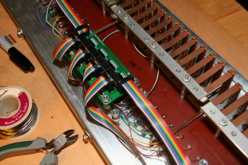
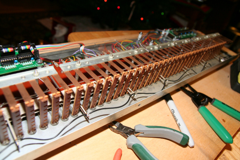
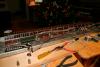
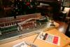
Here's a few pictures showing where I am at right now. As you can see this is the Solo board. I have pulled the working Dins and core off of the push button board now and will be mounting them onto this board now. I will be able to reuse my IDC cables , which works out nice. The dins are arranged for second touch, which will be the second set of dins. But I have the mounts for the first touch, which will be added later. Those dins will be configured in software for first touch for now. But the keypress will be all of the way for this, which is for secodn touch. I wanted to do second touch first for keypress since that is at the end of it. Making a first tocuh would be just crimping a copper wire in the other set of contacts back some. I found out that the #6 nuts have tight clearances on top of the dins and cores (in fact right by one of the midi sockets, there wasn't enough at all). So I may have to switch over to #4 hardware for that. I also found that those rear screws stripped the metal threads. So I'll just drill out the holes with 1/8" bit so they go through the holes. They will be tightened with nuts and lock washers on the bottom anyway. Next I will be running the ribbon cables and measuring from the dins to the contact boards and soldering them.

-
Note: It is important to think out how you are going to be able to easily disassemble or assemble things to do adjustments or repair, etc. The rear 2 screws Baldwin had them threaded on each end, and into the metal. This allowed them to stay put in the metal, but the nut on the bottom secured them more. Since there are spacers between the contact circuit boards, it helps to not have screw heads, so that you can mount the boards onto the spacers and then put nuts on top. I had to go to screws with heads, since the Dins mount over the tops of the screws and I didn't want anything touching the bottom of the circuit boards. But my way is a bit tricky to assemble, etc. Since you need to carefully insert the spacers btween the boards, then screw the screws in, and then add a nut on the bottom. I do want nylon spacers between the Dins and core circuit boards and acrylic. But you can't access the bottom of the acrylic pieces for the screw heads. For a couple of Dins I can premount them on the acrylic. But, sincee a couple of Dins mount to 2 acrylic pieces, I can't. So I had to change the mounts a bit by adding a nut under the spacers so that I can tighten the screws to the acrylic, add the spacers, then just pop the circuit boards on and add a nut on top. This added nut added 1/16" to the overall heights, but I have that to spare, barely. But at least it makes for assembly/disassembly easier. I also added nylon washers on top of the dins and core, just in case the nut may short a run that maybe too close to the holes. This doesn't add any height. I will also put a piece of electrical tape on the rear screw heads to make sure there are no shorts to the bottom of the din and core circuit boards, that mount over them. All of this extra hardware does add up. But, if you are to do something, do it right. Once I am done with my contact boards, I shouldn't have any worries later, if I do it right to start. Also: Before I took out the old stacks of contact circuit boards out I noted the heights to the tops of the leaf springs. Then when I added the acrylic pieces, etc., I figured out how many spacers(I was able to reuse the origional spacers, had enough) needed to bring the heights back to what it origionally was. This maintains the origional integrety of how it was designed. These contact boards were well designed for feel and to last. I wanted to keep that. Too much preasure on the tabs may wear them out, etc. These boards have lasted 40 years and are still good. I want to have another 40!
-
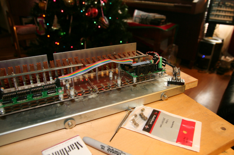
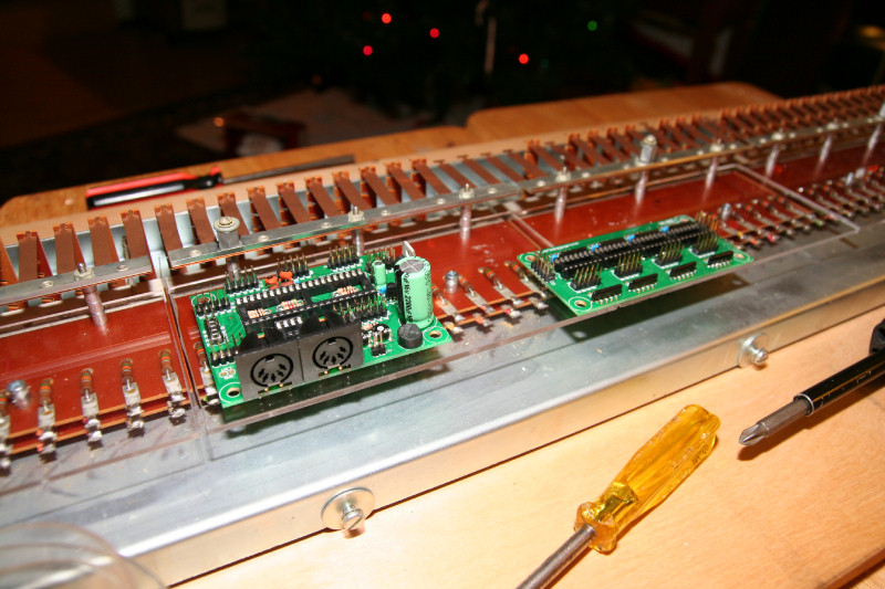
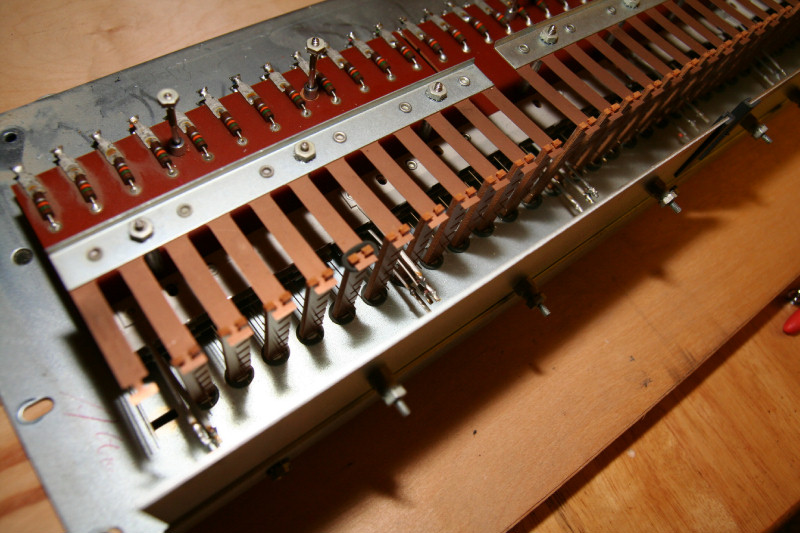
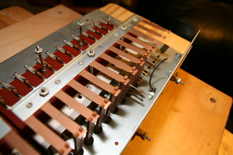
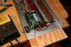
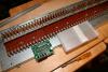
I figured out the placement of the dins and core, drilled the holes in the acrylic, and temporarily mounted them. I had to cut the resistors out to allow for the screw heads that ended up on top of a resistor. I also have mounts for 2 more dins for second touch! Both sets of dins are centered per 32 contacts as I did with the push button board. But this time I allowed for 4 dins. All I need to do is figure out the placement of the fuse holder, and power terminal(both mounted onto the metal part for better stability). As you can see, I flipped the Dins and Core so pin 1 in midibox will pin 1 on Din 1, etc. Now to do the Solo board, and then it's just wiring them up.
-
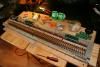
I just finished drilling the holes for all of the acrylic pieces. Only one cracked around 1 hole out of 10 pieces and 50 holes, because I forced the drill bit too hard. This is the plexiglass version, which the hardware store guy corrected me in telling me this is the brittle version. Plus you need to go slow when drilling or cutting acrylic. But that is not bad and that piece is still good. I have them all mounted awaiting measuirements for the core and din placements. I also have all of my hardware with screws, etc. As you see I had to remove one layer of contact circuit boards. After putting the core on top of 3 layers and the plexiglass, and remeasuring the hieght, it was too high. That 2200 cap! But I only need 2 sets of contacts anyway for first and second touch. The rear 2 screws for the contact circuit boards and acrylic pieces I had to change over to 4mm metric pan head. The old ones were non standard(but a bit smaller than 4mm), and were threaded on each end, so that nuts and lock washers went on each end. They also were threaded into the bottom metal of the board. So I had to use a slightly larger drill bit to ream out the holes in the metal a bit(7/64" bit), and then used the 4mm screws to tap the threads. Worked well.I wil also add nuts and lock washers to the bottom as with the other screws. Plus lock washers on top later. Baldwin saw that lock washers everywhere they can be used seamed important, so do I.

-
I just returned from the hardware store with my 3/32 " acrylic pieces. I had 2x 6 7/8 " x 3 3/8 ", and 8x 6 3/8" x 3 3/8" cut. 10 total for only $15, and it took only 10 minutes for them to do a good job. 2 are wider because the last stack of contact boards has 13 contacts. There are 4x 12 contact stacks, and 1 13 contact stack per contact board. 4 x 12 + 13 = 61. I measured them to allow for the core baord which is the widest. Then allowed for about 1 inch in back for the ribbon cables to go. Now to drill the holes and place them in place and measure for screw lengths, etc. I have to get to that point before the hardware store closes today(5 hours from now) so I can get the screws, nuts, etc. I can't tell the exact lengths until I insert the acrylic and measure. Once I have all of the screws and hardware the rest is just soldering and assembling, which I can do later.
-
Crossing my fingers.. I just called my organ guy about the tabs and he thinks he has them. He was on the road so he will call me back later today once he gets home and checks. If he has them it will save me alot of work(hand making them ottu of acrylic with a dremel will take time), and I can feel good with having all of it working. I didn't feel good about epoxying them anyway. This morning I just finished getting the Acccompanment board ready for the acylic pieces. I am nwo awaiting my wife to get home with the car so I can go to the hardware store to get the peices cut.
-
Damn! Looking at the old Accompanment contact board I have 8 broken tabs! So that is 5 from the Solo and 8 from the Accompanment keyboards. I can't swap between the keyboards the tabs, since the stacks of contact boards are different. So for the Solo I was able to move the broken ones to 4 on the top Octive and 1 on the lowest. For the Accompanment I have to do 4 on each end. That leaves the middle Octives all in tact. I have all of the broken pieces of the tabs for the Solo. So those I can try to epoxy and then I would have all of the Solo keys working. For the Accompanment I have all but 2 that can be fixed(2 are beyond repair). I will check with the hardware store tomarrow to get their opinion on what the best type of epoxy to use to repair them. If the tabs can be repaired, I will only have 2 keys on the Accompanment unplayable until I can replace 2 of those. I'll also check with my organ guy to see if he has any, if not I'll have to make them. All of these tabs could have been broken with my dissassembly of the organ, or maybe in a move. I have had this organ for 25 years, and it has been moved a lot, and carelessly a few times. A hard blow to a key may have damaged some tabs. But even with these broken tabs, I am still happier with the old contact boards than with my push button boards. Looking back at the push button design: They did have an OK feel(a bit stiff at the end of a keypress, but not too much), but required VERY precise alignment of the holes for the switch mounts, precise height adjustment(one thickness of a washer can make a big difference), and need to be mounted on a solid piece of metal vs wood(wood even with a slight warp is too much). I will see if I can use the push buttons somewhere else, and the terminals I can put to use somewhere.
-
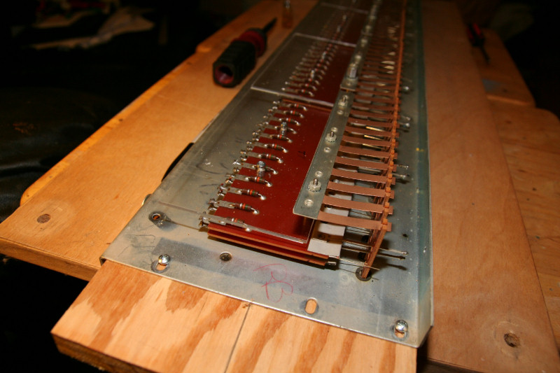
Now that is what I want! The key press is perfect, as intended with these old boards. I was also right in the fact that where I put the copper wire makes a difference on where it makes contact in the key press. Right now where I have the copper wire crimped at would be good for second touch(i.e. you have to press the keys all of the way to get contact). All I need to do on the organ side is adjust for height. I forgot what origionally was inserted between the board, a nut, a nut and a washer, or nothing. See I changed that when I mounted the wood boards in. I should have taken a picture to resort back to. But that is no problem I just need to play with those combinations until it's just right. At least the keys align with the contacts every other way without bending any metal. Now that that is confirmed I will continue with stripping the other board, and mounting and wiring up the dins and cores.

-
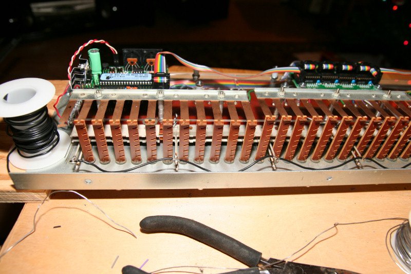
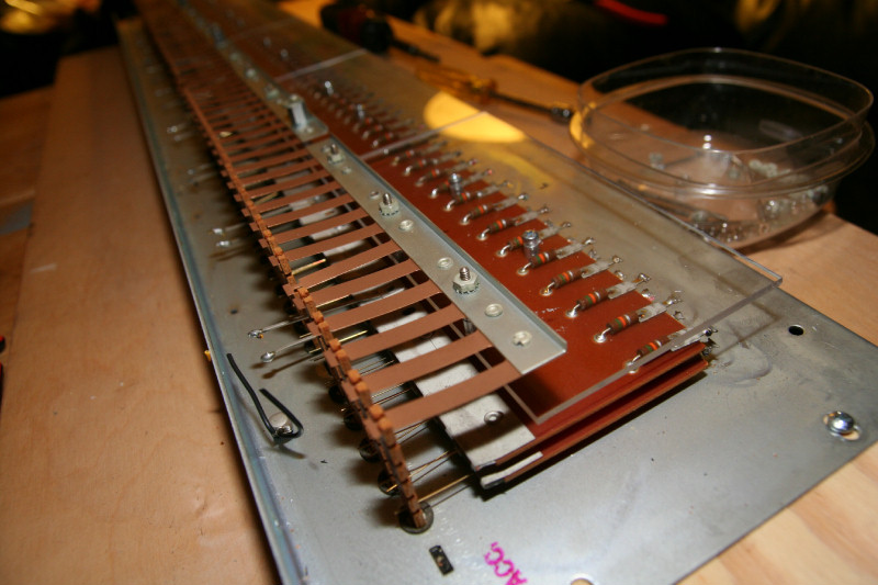
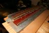
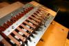
Sheu.. That was tedious work. It took me all night to just remount 2 more contact circuit boards back in. I had to figure out the number of spacers to use to get the right height. I had to carefully insert them so the contact wire springs nor tabs were damaged. Plus I had to put the wires back into the groves in the tabs. The boards with the crimped wires are on top for easy access. Plus if that is to be the second touch I want those boards last in the keypress (don't ask why, it just makes some sort of sense to me that the second touch should be last), which will be on top. Now this board is ready to add the acrylic pieces and mount and wire up the dins and core. I am also thinking out how to flip and rearrange the dins better now that I know how the core sees them, etc. Now this contact board will go into the organ temporarily to check on the contacts actually making good contact, and for feel (I am sure it's great since these boards were designed for the organ), before I continue any further. The organ is also the safest place for it to prevent damage while I work on the other contact board to strip it down. Here's a few pictures for you:
-
I just decided on the size of my acrylic pieces. I will make one per contact circuit board so that it is consistant, and each can be removed to easily work on it. They will be as wide as the contact circuit boards and as thick, but they will be deeper and run to 1 inch of the back of the assembly, to allow for the ribbon cables to route, but stay within the demensions of the assembly. I need to figure out the sizes ahead of time so that the day after Christmas, I will be ready for them, and can go to the hardware store to have them custom cut. This is 3/32 inch acrylic, which is hard to snap just right without cracking it, etc. So I'll leave that up to the hardware store to do. I will need 10 pieces, and they shouldn't be more than $1 ea. So it doesn't pay to try to snap them myself. I know this from experience! Anything under 1/4 inch of acrylic is hard to snap or cut(too flexible). 1/4 inch you cut(it's too hard to snap). But I have sucessfully snapped 1/4 inch with a deep enough grove(dremel guys, they are great tools) Well you can cut 3/32, but why bother when it's cheap enough to have custom done, plus it's too flexible with trying that too without getting cracks. Ace hardware does a good job, and if they crack any, you don't pay for them. I'll drill the holes though. I have worked with acrylic in my aquarium DIY stuff. I like glass for the aquariums and sumps, but acrylic for overflows, etc. I love acrylic where I can use it. It doesn't rust, dry out(well it can but many many years). It's easy to work with to make all kinds of stuff with. Plus it doesn't conduct electricity, which is good for where you don't want that. It will look neat too(just wait until you see my completed assembly). It would work great for the tabs too, since you want non conducting material for those since the contact wires go into their notches. There is a version of acrylic that is called plexiglass, which is more flexible, since some acrylic is brittle. The hardware store version, I think, is plexiglass. I do want that for the tabs(when or if I decide to change them over to acrylic). That is because the tabs have very narrow areas in the notches that if the material is brittle, they can break easy, just like with the old material of the tabs. I don't want that! The pieces that I'll mount the Dins and core to, can be flexible too(well 3/32 will be), since the screws will firm them up, as they do for the contact circuit boards, so the mount should be solid. Lexon is another version too(little harder to cemment I think though), I think is at Home Depot. I can get black or clear in either, just depends on what is easily available, etc.
-
Well I just switched over to Jorgan now for the front end of the virtual organ part. Miditzer was nice to start but now for complete customization of my console, etc., I will be working with Jorgan next. I am using an example disposition of the Wurlitzer 260 for fluidsynth. Although the Wurlitzer 260 is written for 3 manual organs, I like all of the bells and whisles. I will map the Solo and Great together for the Solo keyboard of my organ. For some reason I had to set the channel in Jorgan to 0, for channel 1 of the core. But the midibox works great with Jorgan now too! Eventually I want to load real sound files and send them out to the apropiate sound channels(3, including the leslie). I am using the fluidsynth version right now because I am using the realtec integrated sound on the motherboard of the organ computer. But I do have some nice soundblaster cards to install later. I just have to figure out how to send the right sounds out the right channels, etc. Right now the sound DOES come from inside the organ, but that is with 2 small 10w powered speakers, I just set inside of the organ. Later I will see if I can use the old amp of the organ(installing new caps, etc., and adding preamps, etc.). But I'll need to get the full Baldwin 210 schematic (he can get me the full repair manual with the schematic for $40) and some help from my organ guy. He has been working on organs for over 40 years, and knows the electronics inside and out. I am a bit rusty on the electronics parts, but better on the programming. It's good to know an old organ repair person for parts, and knowledge, etc. I DO have the origional owners manual for this organ! The owners manual explains how the different stops and keyboard sounds are routed. But it doesn't explain the Rhythm too well. It's been so long since I played the organ that I forgot what some of the stops did and sounded like. I do want to sort of mimic the old features, but then add to and improve upon them. Miditzer was a nice start, but I want full customization. I will also be using photoshop to design my own skins, stop tabs, etc., for my console. I would like to start with Jorgan, at least as a front end. I did play with Jorgan before and started making some custom dispositions and skins, etc. I changed the stop tabs heights to not pull out so far, so that I can put them all on the screen, etc. I also took pictures of my organ's console and stop tabs to use too. So I know a bit on how to configure it. I am not digging too deep into the programming right now, just trying it out(but I'll come back to it later). So don't worry, I'll be back to the construction with plenty of pictures for you, showing each step :) I almost forgot:Ho Ho Ho. :o I am Santa Claus right now and just finished putting the gifts under the tree for my son.