tonyn
-
Posts
203 -
Joined
-
Last visited
Content Type
Profiles
Forums
Blogs
Gallery
Everything posted by tonyn
-
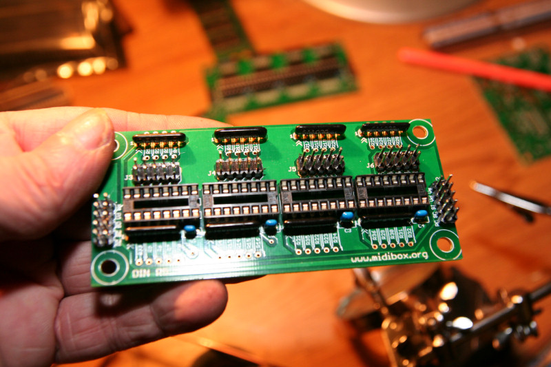
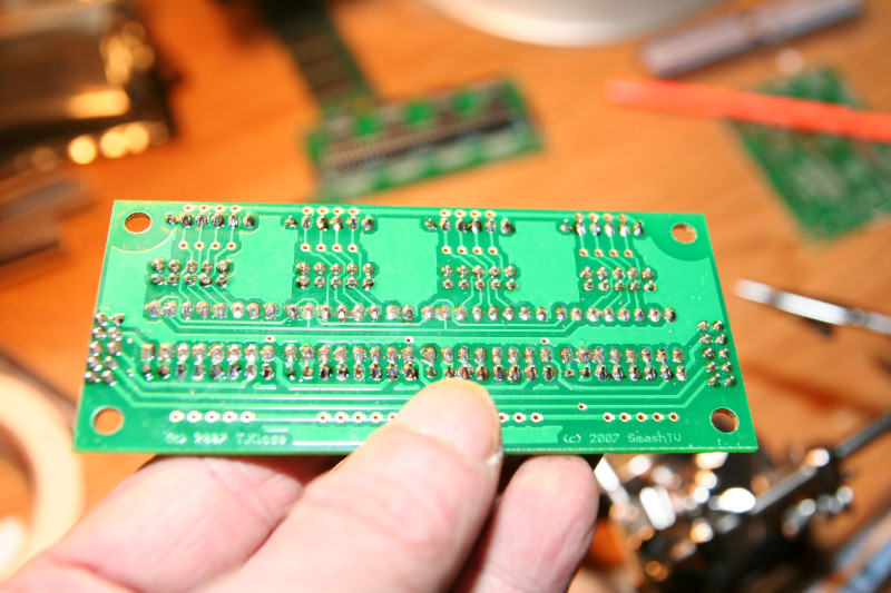
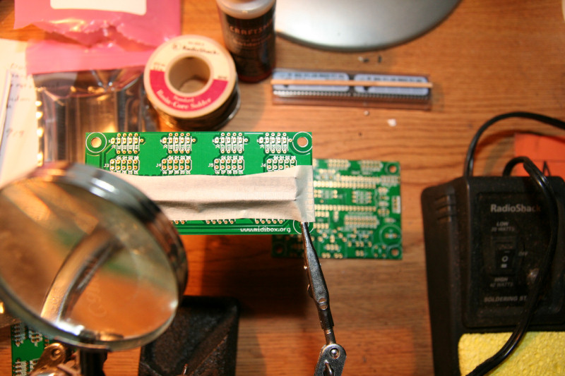
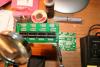
Shew.. I just finished soldering all 4 Dins(I am doing just enough right now for the keyboards). I didn't bend the leads to the caps, just in case you are wondering. I instead taped them in line with the resister networks and cut the leads to be the same before soldering. The assembly was: IC sockets. j4-j6 headers J1-J2 headers. Then the resister networks and caps. Yes, there are ICs. Those get inserted last. I'll clean the circuit boards tomarrow and reinspect them. Now onto soldering the cores.
-
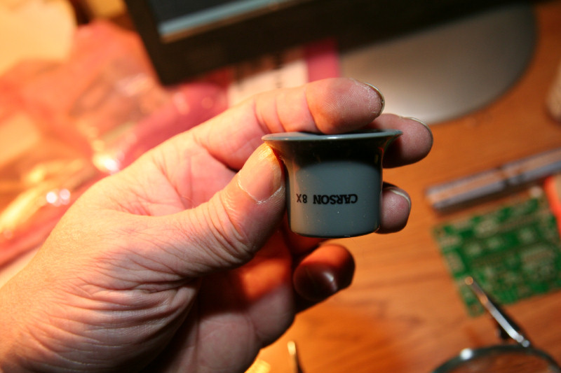
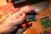
Another nice tool to have for examining circuit boards for shorts from soldering, etc., is this. It is a high powered magnifying glass you insert into your eye. I think it is called a Lope. For circuit board work you may need exacto knifes. jeweler tools, dental tools, etc. But I shouldn't need those for this. I use the Lope instead of the magnifying glass on the helping hand thing as I solder too. Here's a picture:
-
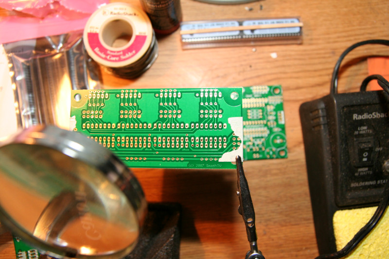
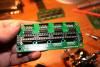
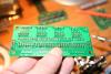
Well the IC sockets are soldered in. This is sort of what you want to see. I still need to clean the solder flux off the board (you need to clean the solder flux off, which comes from the solder, else it can cause a short circuit). I like to use tricloride with a tooth brush. This is what is used to clean circuit boards. I don't have any handy, so that will wait until tomarrow, and hopefully the hardware store carries it. In the USA some chemicals are hard to get. If I can't get that, I'll have to use alcohol After all of the components are soldered into the boards, I will clean them and test for shorts. If there are any shorts from solder overflowing to a trace or pad, I can touch up the solder joint to remove the short, etc.
-
First I will start with the ic sockets. Those are in the middle of the boards and low profile. Usually it's a good idea to start with the lowest profile components so you can tape them to the board easily. You can also choose to work from the middle out too, as I decided to do. I'll give you a soldering tip too: When you solder, bend and cut the leads(only for leads that are long, like on the caps) so the solder can cover the ends. Components like the caps are harder to tape, so by bending the ends, and turning the circuit board over, they will hang so you can solder them. Cutting the ends before soldering also helps from corosion later. When you solder you want just enough solder, but not too much, and DO NOT HOLD THE SOLDERING IRON TOO LONG. You feed the solder from the left with the iron on the right just touching the pad and lead so you are heating the lead and pad, you push the lead slightly as you solder to make sure the solder flows onto the lead and into the hole and to the pad. As soon as the pad is covered, you pull the solderig iron up and solder away quickly, and up so the solder gos up the lead and covers the end. For pads that are connected to ground traces(large traces)you may need to heat it a bit longer. You do not want to melt the lead or tin out(I forgot which), and make the solder joint brittle, and non shinny. You want it nice and shinny, and concave(you don't want a bump of solder, just enough to flow into the hole, suround the end, and cover the pad). You can also burn away the solder pad, and destroy the board if you are not careful, and you have a hot soldering iron(past experience). I usually set my iron to 40w, which can actually burn the pads off of the circuit boards and destroy them. But the soldering gos quickly. You just have to be fast enough to remove the iron before damage occurs. This takes practice. I do not recommend that for beginners. Set your iron to 20-25w for circuit boards. It takes practice to get a good solder joint. I'll show you what it should look like. Use a lightly wet sponge to keep your soldering iron tip clean too. Your soldering iron tip should be shinny too but have no solder on it. You tin the end of your soldering iron with solder It's the rosin core of the solder that helps make things flow better too (so make sure you get rosin core solder), wipe it off on the sponge, before you solder. That makes it shinny and helps melt the solder, etc., better. What I do for a good solder tip is sand the tip down to the copper first, and then apply solder to it to tin it before you use it. Then you keep it clean and shinny between soldering, and remove old solder, by wiping it on the sponge. I also have a bottle of solder flux in case I need it(this is usually used to tin wire ends).

-
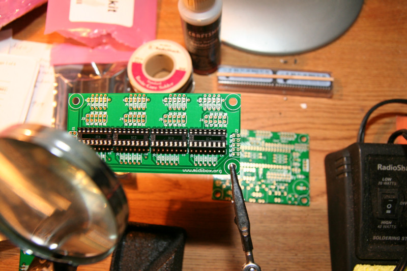
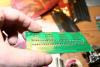
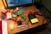
Just a quick picture of my circuit board soldering setup. I haven't populated the din board yet with the components. I am basically just getting ready. Those helping hands come in handy. Part of any type of construction is having the right tools too. I am always working on some type of project, electronic, etc., so this I already had laying around. There are also are some tricks in inserting the components for easy soldering I may share with you too. Like I said: I have been doing this type of thing for over 30 years, so I know a few tricks. I have even etched my own circuit boards. But I don't have access to good etching and silk screen equipment. So I ordered them from avishowtech. I am happy with his boards. High quality good price, and no headache for me to have to order or have them made elsewhere You can send in circuit board layouts and there are companies that will make them for you, but you usually have to order a quantity for it to be worth it. Then you need to order the components, etc. He takes the hassle out of getting the components too(if you order the kits, as I did). All in one shop for this. Plus although I was initially impatient awaiting them, it only took 4 weeks, and is worth it! That guy must be real busy for one man, and that is fast considering.
-
OOPS. This was a double entry...
-
OK. I am in a delema right now: Do I use terminal strips for the switches, or just solder the wire ends to the ends of the ribbon cables that go to the dins? I may just start with the soldering, since it would be easier and better contact actually. I will leave enough wire to cut and resolder etc., later if I need to. Then I can consider wiring to the terminals later(I already have a bunch of terminals as you saw, to do that).
-
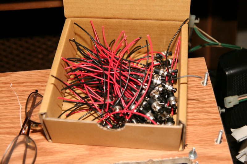
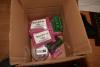
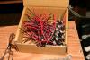
Thanks. I wish you luck with your organ. I haven't even looked at the contacts of my pedal boards. I am hoping that I can just take off of the old contacts. But I may have to redo the contact board for the pedal board too, which I am not looking forward to. So, if you are lucky, you will get a pedal board that has contacts you can just take off of. So, if you are buying, check that part out first, since it may save you a lot of headache. My pedal board also slides out, which is nice, and I want to maintain that, since my organ is in a small living room and having the pedal board removable is nice, since it takes up room, and can cause tripping when not used. So, in your case where you are using a separate pedalboard with a synth, See if you can get a removable one like mine. Then you can build a box that lets the pedalboard slide out of, etc. My organ is from the 60's-70's. But after 1990? they started midizing the organs. Those would have nice contacts to use. So, if you are buying or getting an organ, look for later models to save time and headache. Just my 2 cents. I am stuck with mine and have the headache of redoing things to midize it. They are cheap too. My organ guy had a later model midized Lorey for only $200! I told him I may want some parts from it later for the stops etc. to use for my organ. That's if he still has it. He told me tht if he doesn't, he has tons of stops, etc., from different organs I can get for cheap from him. He really wants to sell the organ as a whole, since it's fully functional. I have a good resourse myself for organ parts! Yes, I have considered Hauptwerk. I DO want the quality. But I am starting with Jorgan and Miditzer to "get the feel". I also have the free clone version of Hauptwerk called MyOrgan (I can provide a link to it for you if you want) to play with too. I don't need to spend money on Hauptwerk, since I am a programmer myself:) But I may have to buy some soundfonts. Then, as a programmer, I plan to develop my own customized programs. I am thinking Java since Jorgan etc. are programmed in Java so I maybe able to use them, add to Jorgan with my code to help upgrade it for that guy, and then write my own programs. I am taking advanced Java programming this next college semester too! Java is also cross platform and I plan to change the operating system over to linux. I want the computer to boot up and ready to go when you turn on the organ. It will boot up with a custom configuration that won't need the touch screen, etc., and use the normal stops, etc.. But it will also allow you to pull up other organs that will use the touch screen, which will be the nice part of the virtual organ part. The pedal boards will be a bit of a pain, since to access the pedal contact boards I have to lift up the organ, etc. But I am aproaching this one step at a time. First the keyboards and outputs of the sounds to the 3 channels(3 100w speakers, including the leslie with control of the leslie motor), then the pedal board/swell, and then the stops. BTW I just got my order from avishowtech(I'll include a pic). I ordered 9 din kits 4 core kits and 20m of 10 ribbon cable along with 58 IDC connectors. So I have enough for it all except maybe some Douts later for the stops I may want the computer to be able to physically set/reset stops, so I'll need Douts for that, but I'll need to change the stops over to push buttons with leds and latch circuits, etc. The leslie motor control will also need to control a relay, etc. I plan on using 4 dins and a core for the stops and pistons. 2 dins and a core per keyboard, and one din and a core for the pedalboard and swell. So 4 midi channels and 4 cores. I ordered the core pics preprogrammed for channels 0-3 Just an FYI: This order was over $300, but well worth it. I made sure I had more than enough, since you never know (I may destroy a board soldering, not likely since I have been soldering circuit boards for over 30 years, but you never know). It's always good to have more parts than you may need, just in case. I can always run the 2 keyboards off of one core if I want to or need to later. But I like the separate channel configurations I plan on right now. After I solder the din and core circuit boards and have the keyboards connected to the dins and cores, I'll be testing out and programming the outputs to the computer programs, etc., and then figure out what will work best So now it's time to get to work! I have a bit of soldering to do now.
-
OK. I am back. Bet you thought I had given up. I just had to finish up my fall college courses that's all(I am an A student too, just for your FYI). I now have about a month to work on the organ. My dins and cores have been shipped today too! So within the next couple of weeks I should at least have the keybpoards working with Miditzer, etc. So I'll be able to somewhat play the organ for Christmass! I love playing during the holidays. I have a lot more work to go after getting the keyboards midized. I have to think out how to amplify the outputs from the sound cards to 3 channels, etc. I hope to maybe be able to use the existing amp. But I may need to build preamps, etc. Then I'll need to work on the pedalboard and swell pedal, and then: How to midize the stops. I may just gut out the old stops and get some monitary push button latched ones from a midized modern organ. My organ guy said he has some. But that will take some thought. I may also have to order soem Douts for the stops too.
-
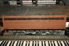
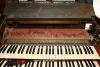
Don't worry I haven't quit. I am actually 50 years old, and have a background in electronics and computers. I took some computer science courses 20-30 years ago, and have been programming building and repairing computers for over 30 years. But I have no computer science degree. So, last summer after my business went bankrupt, I decided to go back to school to finally get my computer science degree. I am a full time student right now(an A student, feels good to show up those 20 years olds) with a full load. I have been working on this along with doing my school work. But I need to finish my courses for this semster now, and dedicate full time to that right now. So I'll be back at this in a about a week, after my courses for this fall are done, and I have some more time to devote to this. For those of you also wondering: Yes I am a musician too. I didn't just inherit the organ, I can play it too! I studied when I was a teenager on various chruch organs and learnt from some good teachers. This is why I want the feel just right. I also want to be able to play it again soon. As you can see it all works as planned so far. All I have to do is wire up the terminals. I'll take pictures for you after I do that part too.
-
OK. So far I seem to be talking to myself. But it does look like you guys are viewing this thread. But if I can share with you that's fine. For me this is a way to share some of what I know and some tips along the way. Plus it's a way for me to document my progress for my reference. You guys may also think I am putting too much work into just the keyboards. But, to me it will be worth it in the end. The pedal board and swell pedal will be next. The part of midification of the keyboards is the easy part. Although it looks like it's hard it isn't, just takes a bit of work. But I feel this way to me is the best. Just wait until I get to the stop tabs and of sending the various sounds out of the 3 channels of the virtual organ programs to the real organ's speakers (2 internal speakers with a leslie speaker, = 3 channels), and having it all work through MIDI from the computer. I do have more sound cards if you looked in the first picture(still in their boxes sitting beside the computer ready to be installed). They are new sound blaster cards. The computer has an onboard sound right now that I am playing with. I have played with the virtual organ programs on other computers I have laying around the house before I purchased this computer, so I am familar with them and have been working on my virtual baldwin console in JOrgan. Of course I also have the wonderful Midwurtzer progam too. I have also input midi keyboards to these progams to test out too. So I am a bit famular with that part. I plan on 3 sound cards with 3 sets of sound fonts for the 3 channels, etc. I also have the origional Baldwin 210 manual that explains how the sounds are routed, plus I have a schematic of the old Bladwin 210 organ to help. Plus I have this organ repair guy that has been repairing organs for over 30 years and knows them inside and out. He has tons of organ parts or can get them for me, including midi controled parts. He knows the electronics, but doesn't know much about computers. So I am bartering with him for my knowledge of programming and computers for parts, and his knowledge of the electronics of the old organs. I may strip out the old stops and put in lighted ones that can be activated through din out and midi too. I have my ideas on that too and will start with the plug and play programs to start, and then write my own. Plus there is the carpentry work of fixing the damages to the wood, whitening of the keys, etc.. This is a multi month project so stay tuned.
-
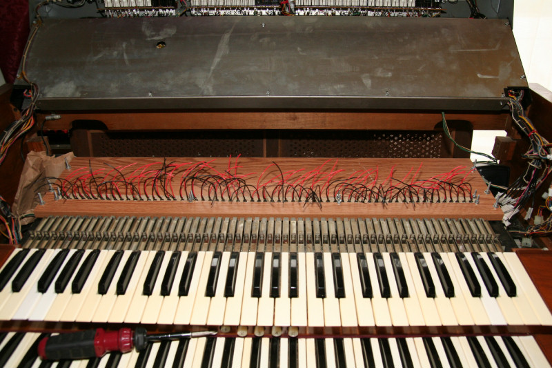
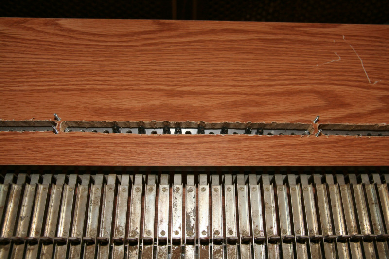
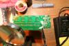
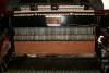
OK. I just installed all of the switches for the top keyboard. This is the first time I was able to feel what the WHOLE keyboard feels like with these switches The feel is great! Nice and solid(better than cheap portable keyboards), and just right(not too firm nor too soft). That rubber coating dampened all noise and also will help keep the switches and screws from coming loose from vibrations, etc. Right now the switches make full contact when the keys are within 1/8 inch of all of the way pushed down. But I can always adjust the height for ore exact contact height a little with washers. Like I origionally planne: I took into account to the ability for minor adjustments if needed. Plus, if a repair tech needs to do any repair it's easy. Each switch can easily be removed and replaced. Switches do go bad, so this should be easy. Now it's installing terminal strips and attaching the wires from the switches to them. Here's a few pictures for you:
-
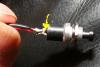
Sheu.. I just finished soldering the rest of the switches. I have 130 good ones but only need 122. So I have 8 extra for spares. Later today I will be aligning the holes to the key hammers, installing the switches, and attaching the wires to terminals. When installing the switches I will have to install from left to right, one at a time, to allow my open end wrench to be able to tighten the nuts. Note: While I was doing my QC testing of these switches, I was able to fix a few that were not completely assembled right. There are little lock tabs on the terminals on the back of the switches that need to be locked. If you have a switch like this(I don't know the real manufacturer, but they were bought at Radio Shack, made in China). With no continuity when button is pushed, it maybe due to a loose terminal on back of switch. Just pull the loose terminal out until it locks. Here's a picture of one of the switches with an arrow pointing to the lock tab of the terminal.
-
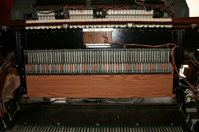
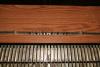
OK. Today I finished redoing one of the metal strips, and opened up the channels a bit more in the wood boards, so that the switches fit all of the way through, and metal strips will fit flat to boards. Before I had to space them a bit away. This will be more solid attachement. I also just rubber coated one side of the metal strips, with a thin layer of plasti coat. I will coat the other sides later. This should dampen any vibrations and also help to keep nuts on. Here's a picture of the coated tops of the metal strips:
-
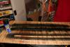
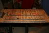
Well it took me about 5-6 hours to do it right. But I have finished soldering the wires onto half of the switches. 62 actually. The rest will be done tonight. I decided on 4 inch lengths of wire, since that should be more than long enough. After the swithces are installed, I will measure distance to terminals and cut and strip those ends. Here's a picture of my progress:
-
It's always important to get a few extras of things, especially when it comes to electrical components. I got 132 switches although I only need 122. Then it's important to test out electrical components before soldering or installing. If you have the equipment, in the case of switches, a continuity tester. I tested all switches both mechanically(spiring and sitckiness, etc.), and electrically. Out of 132 switches 1 was machanically bad(sitcky spring), and 1 was electrically bad(no contacts when switch pushed). These were made in China, and yes if you buy something made in China, make sure you thoroughly test it out. They have no quality control in China. Now onto soldering wires to them.
-
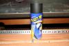
Damn! You may have noticed that one of my new metal strips has a hole that is bad. These yard sticks had holes on one end to hang them in the store. I wasn't paying attention to how I aligned the one strip and now I have 2 holes where one should be. So I'll have to make another strip(61 more holes). Oh well..That can wait until tomarrow. Tonight I'll be soldering the switches and maybe plasti coating the strips. Anyway in case you guys are wondering what I was refering to for a rubber coating. It's called Plasti Dip and is used for coating tools and other things. It comes in a spray can or as a dip. It comes in 4 colors(red, black, yellow, and blue). I got black. Here's a picture of it.
-
All works well so far. Plus I may not need any dampening. The switches on the old metal strips wre not tight because I couldn't use lock washers. The sounds I must have heard may have been from that. Now that I can use lock washers those sounds doesn't seam to be there. But everything can be dissassembled, and I can always coat the metal, etc. There is always the options of nylon washers etc. to help dampen things if needed. Now it's basically soldering wires onto the 122 switches! I'll be using red and black insulated 22 gauge. This I can do tonight.
-
OK just in time. It's night time now and I just finished with the power tools. Here's a picture of what I just finished: Drilling the holes into the metal yard sticks! You can see my makeshift workbench I am using. Now you know why I am slightly off. I used the old metal strip as a template to make it easier. I did both yard sticks at once. Yes I could have made it more precise in this drilling, but it was just easier to use the old metal holes instead of worring about bit slipage(I may have done worse). These holes are close enough and it saved me time. I hate redoing things, but I needed thinner metal strips.
-
Another picture for you guys. I cut out the channels so if the switches are off they will fit fine. I used a jig saw instead of a router. It was easy and fast(just connect the dots so to speak).
-
Here is something I found that may work to whiten yellowed keys: http://retr0bright.wikispaces.com/ So I may try this later to whiten my yellowed keys.
-
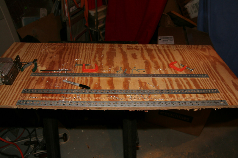
It's late at night. Usually when I work on projects, the day time is mostly spent running all over the place to get the materials. I always make sure I have everthing I need before I start a project. I hate running out of something in the middle of a project. Unfortunetely when using power tools at night I can disturb the neighbours. So all I can do now is plan for tomarrow. But here's a picture of what I plan on doing. Yes, my holes are off slightly. This is because I started out with drilling the metal holes and the drill bits slid a bit. Then I used the metal strips as templates to drill the holes in the wood so at least they aligned with the switches. I hope to fix this now with routing out the holes in the wood for a nice channel and centerpunching the metal yard sticks for exact alignment. You can see the metal yard stick. These were $3 ea, $6 total for 2. The terminal strips are for the hot side of the switches. They come in strips of 12, so I'll need 6 per keyboard((3 x 12 +8(4 cut off)) = 32) x 2 = 64 with 3 left over, at $3 ea for a total of $18 per keyboard. If I tried to make my own terminal strips with screws nuts, etc. I am sure they would cost more and be a lot more work. These terminals will be towards the rear where the dins will mount, in front I will need grounding strips. I haven't figured out what to use for that yet.
-
I just purchased the rest of my switches, and while I was at Radio Shack, I found some ready made terminal strips at Radio Shack that will work and save me time. The guy at radio shack also suggested that I buy a couple of metal yard sticks, which are aluminum and thinner than my metal strips. They will work better and allow lock washers! I just have to drill 122 more holes that's all. Coat the yard sticks with rubber and I am good. Instead of reaming out the holes in the board I am considering just routing out a channel.
-
OK. I think I came up with a couple of solutions. I will ream out the holes in the wood boards slighty so there isn't any tension when trying to insert the switch strip. Optionally I will coat the inside of those holes with a rubber coating to dampen any noise from vibrations of switches to board. The way I am assembling the switches will be: First each switch needs wires - so I will be soldering black and red 18-22 gauge 2-3 inch wires onto the switches before inserting. (These wires will come up through the holes and attach to screw terminals). I will ream out the holes in the metal strip slightly and coat the metal strip with rubber including the inside of the holes. This will dampen any metalic noise eminating from the metal. I will then insert the switches into the metal strip and add loctite to the threads. Then more holes to be drilled(244 to be exact)! I will be making terminal strips. There will be 2 terminal strips per board with 61 screws washers nuts etc. One strip will be mounted in front of the switch holes for the ground row(there will be a bus wire running from terminal to terminal). The back row will have the red wires that attach to the dins. These strips will be made out of 1/4 inch wood molding strips and attach to the boards with screw or glued(haven't decided yet). First I will make and drill out one terminal strip. This strip can then be used as a template for the other three. This is how I make it all as exact as possible. This should make a good switch board that dampens sounds and allows easy removal of each switch(all that would need to be broke would be the loctite, which can easily be broke). I'll post some pictures of my work for you to see. I am just thinking out load here. I may change my mind as I go. Feel free to add your thoughts. Maybe I sould do this as a blog?
-
All is good with my DIN and CORE kit MIDIBox orders from avishowtech. So now to get back to work on my button board. Here is what I found out and am trying to come up with solutions: Since those holes in the 5/8" board are not quite perfect, and just slightly bigger than the outside of the switches, when I attach the metal strip with the 8 screws the switch bodies are too tight and the switches may break. So I need to ream out the holes in the board some more. My other delema is that the metal strip is a bit too thick to allow the O ring lock washers that came with the push buttons to mount and lock the switches to the metal strips. Since these switches will see a lot of hammering and vibrations they could come loose. So I am considering Loctite Blue 242(locks nuts but can be removed later, it's semi permanent). Then as an extra I may use some liquid rubber around where the switches mount to the metal strip to not only dampen the metalic sound but to keep them from further movement in and out. Rubber and loctite blue 242 will allow disassembly later(rubber can be cut, or broke, the loctite blue loosens with applied heat if needed). The last concern is that when the key hammers strike the switches you hear a metalic sound resonating from either the metal strip or vibrations from it to the board. So I need to quiet that. Possibly by using either liquid rubber as gaskets or black silicone between the metal strip and board and possibly around the switch bodies(painted around inside of holes in board to dampen and vibration from switch body to board).