tonyn
-
Posts
203 -
Joined
-
Last visited
Content Type
Profiles
Forums
Blogs
Gallery
Everything posted by tonyn
-
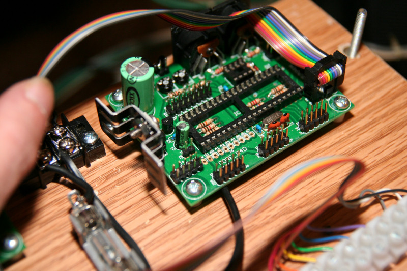
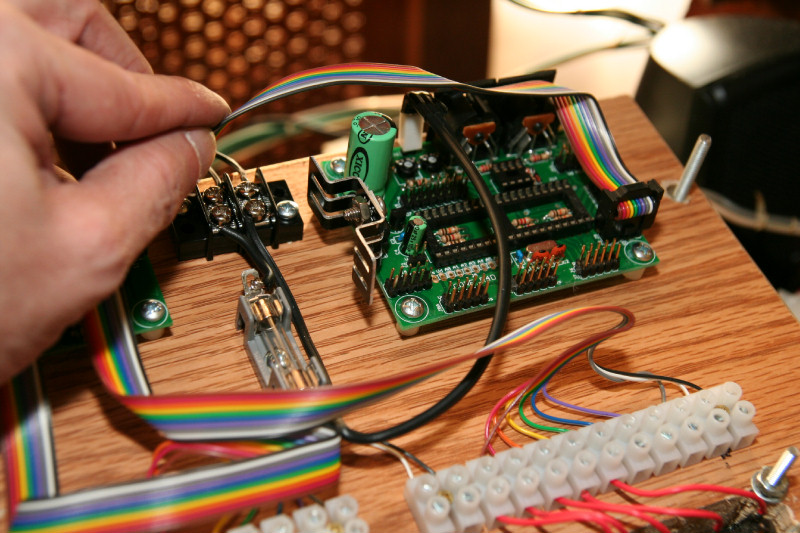
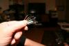
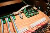
I just wasn't too happy, nor confident, with that wobbly molex, etc. So I just decided to forgo the molex header for the power pins and just solder the wires to those pins instead. Now I not only have a secure connection, but I was also able to route the wires under the board. Now I can power it up with confidence.

-
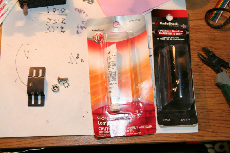
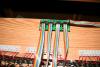
Finally! I am finally to the point to start powering things up, do electrical voltage and short tests, installing the ICs, testing the core from the computer and loading midibox on it! I first went to the hardware store to get the wire for my power. I can buy it by the foot there. I ended up with just 2 conductor stranded 18 guage lamp cord. Good enough! Then it was onto find a power socket for connecting the power adaptor to, or something. I ended up with 2 conductor barrier strips for that, and the heat sink compound at radio shack. I then went to American Science and Surplus for the heatsinks (I remembered when I got some there for my last project, that they had them for cheap, $.15 ea), and while I was there I picked up 3 9v 1 A power adaptors for only $3ea(I already had a couple, but they were so cheap I couldn't resist). Since they are 1 amp, and if both of my keyboard cores draw less than 500ma each, I can use one adaptor to power both cores if I want to. Hardware store for the screws, nuts, and lock washers for the heatsinks. Yes, I may have over done it with the 18 gauge. 22 gauge would have been sufficient, and worked better. Plus the molex with the 18 gauge is too stiff, somewhat wobbly on the header pins(I may just solder it on if I have problems), and I couldn't route it under the circuit board as planned, etc. But for now it should be fine. This is my alpha version of everything! I do plan on improvements down the line. Anyway, here's some more pictures. Now to cross my fingers and power it up.


-
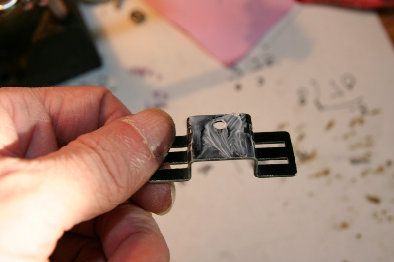
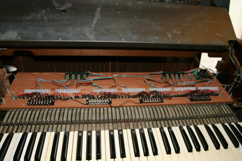
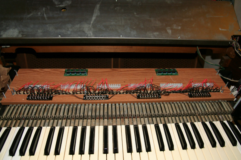
Getting there! One step at a time, taking my time, planning ahead to anticipate any corrections, etc. Although I am confident in my work, I also very my work as I go, so if there is a problem later, I have eliminated some things. So the lengths of the ribbon cables maybe a bit long, but if I need to trim or replace an IDC I have enough length. I gave myself about 3 inches from the farthest reach. Plus, they are all the same length, which to me is important, as every switch will offer the same resistance to the Dins that way. I just finished wiring up all of the switches to the Dins! As you can see I tapped one of the ground terminals to route to the barrier strip for the ground bus. One per din. No need to wire every ground from J3-J6, since they are tied together on the circuit boards. I just picked one that routed over easily. I left 2 spare terminals on my barrier strips just for that. They are sort of centered , so I picked up the ground from J3 on the first din, and J6 on the second. In fact, I would only have to tap one ground from one din, since both dins are tied together with grounds. But , redundacy you know:) Besides, I will be testing each din out electrically at a time, so I'll need each one to have a ground to isolate it for that at least, etc. I hope those dual row IDC work OK from the Dins to each other and to the core. Those cables I should have used 5 pin female headers. Espescially to J9 of the core, since J8/J9 are together. Oh well, we'll see... But the IDC work well for J3-J6 to the switches. My next step is going out the the hardware store, or electrical store, to see if I can get a couple of feet of 18 or 16 gauge 2 conductor for my power pin on the core. 18 or 16 gauge should be about right for the power. Whichever I can get a red/black or a black/white in that fits into the molex connectors (to keep with the standardization of electrical codes, black/white, black is hot white ground, red/black red hot black ground) Update: I looked up the specs for my molex connectors and they can handle 18-24 gauge. So 18 it is, or smaller if I have to. I'll also grab a couple of heatsinks for the 7805s. Since there will be plenty of air flow around my 7805s, heat sinks may not be needed, but it will keep them run cooler anyway, and it's good practice to use heat sinks. BTW For those of you thinking that over 1 amp per core power adaptors maybe needed: 7805's are usually rated at only 1 amp. So if your core draws more than that the 7805 will blow anyway! So 1 amp per core should be all you need max. It doesn't hurt to have more to the core, but your core doesn't need it. In fact if the core draws close to 1 amp, time to think out how to add more cores to spread the current. I only have 2 Dins conencted up per core, so I should be more than safe. But when I do the stop core with 4 dins and 4 douts, if those draw too much, I may have to add another core, or upgrade or bypass the 7805 with a separate 5v power circuit, etc. An alternative to power adaptors would be using computer power supplies. They offer nice rectified, etc., power in the voltages and current you may need. Then you can eleminate the 7805's alltogether, etc. I may do this for my stop tab and piston core circuits. That way I have 5v and 12 volts for relays too if I need to use 12v relays, which I will need for the leslie motor or treminal stop tabs, etc. It's good to plan ahead. Now, when I get to that core I will just eliminate the 7805 crcuit and use header pins, etc. I'll see when I get to that point. My mind says redundacy again: If I need separate power for relays use a separate power supply, etc.. I may use the 7805s anyway if the current draw for that core isn't too high, powering the core with one power supply and the relays with another, etc. But at least I have it thought out a bit in case I need to go this route for that part. Here are some pictures...
-
One step at a time... I just finished stripping the ribbon cables for the J3-J6 headers. I used a scissors to cut about 2 inches between the wires in the ribbon cables first. 2 inches is fine to start, as I attach the ends to the terminals I can pull them back more as needed. You need to be careful when doing this to not cut a wire. But the film between wires is soft, so you can tell that you are cutting just inbetween. Then I striped the ends 3/4 inch and looped back to double the diameter. But I first tested this out with a spare piece of ribbon cable to a spare terminal to make sure it would not pull out with jsut doubling ti back. These terminals handle down to 22 gauge, and ribbon cable is 26 gauge, so I had to increase the diameters. I also made a spare ribbon cable cut to the same length for the second keyboard for a referance, etc. Since both keyboards are the same I am using the first for referance for the second. Best to cut to length before stripping and attaching, since it would be hard to measure the second keyboard's ribbons then. I also made a mistake with one wire from one cable cutting it instead of stripping it. Good things I have spare parts. Then I soldered the ends and cut away any stray wires. This way I now have good solid ends(the screws in the terminals may tear the strands if this isn't done first). Here' a couple of pictures.
-
Just some thoughts... After I have the keyboards working, my next job will be tackling the pedal board and swell pedal. I am hoping to be able to use those old contacts. But I read in the Miditzer forum where another guy had a baldwin and found the contacts to have too much resistance or something. Either way, if I can use the old contacts for the pedalboard, or I have to do a push buttoboard, etc.: I plan to mount the Din(one Din is all that is needed for the pedalboard) and core behind the keyboard switch boards in the top section of the organ. There is a nice space to do that behind the switch boards. All that will go down to the pedal boards are the contact wires. That way all circuit boards are easily accessable. Unless there is too much resistance in the wires leading from the Din to the pedal contacts. Then I will have to mount the Din Closer to the Contacts. I'll try to use the largest gauge wires(12 or 14 gauge), to cut down on resistance in the wires. I may also see if I can color code them simular to the ribbon cables, so everything is consistant with the keyboard wiring too. I'll only need 26 wires running up(excluding the swell). 25 for the hot sides and one for the ground side. The ground sides will be bussed in the pedalboard area. Yes, terminal boards too if I can(but bigger ones to handle bigger gauge)... All cores wil be daisy chained from the top one, which is channel 0 for the stops and pistons, to the last one which is channel 3 for the pedal board and swell. The last one in the chain will have midimerge installed (or the first, I'll see which works best when I get to that point). The chaining will be from midiout to midi in, in order, leaving a spare midi in for the top core. The top core for the stops will also have Douts to allow the stops to be activated too by the software! By having that core the first in the chain, allows it's midi input to go to the computer too! Since the computer will output to that core to activate the stops, it needs an open midi in. At least those are my plans. This is subject to change..
-
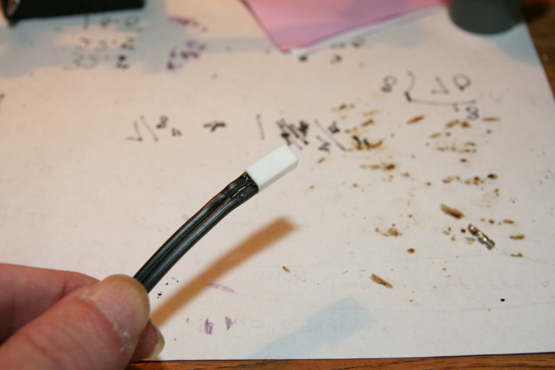
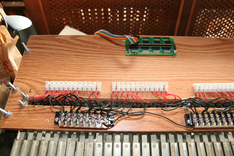
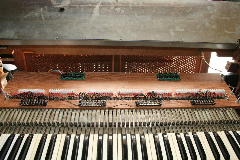
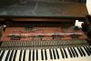
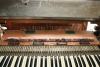
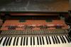
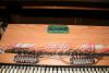
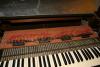
I thought I would take a short break and show you where I am right now. It's important to take your time when you are designing and working on a project. Less chance for mistakes that way. I just finished mounting the Dins, core, and fuse holder to the board. I started from the left and centered the first din in between the first 40 terminal points (don't forget I am connecting up all 10 wires from each header to a terminal point 4x10=40). Then the same for the second din for the last 40. I then spaced a bit and mounted my core. Inbetween the core and the second din is the fuse holder. I will use the power header with a 2 wire female connector. While looking for my LCD modules, I found a few new molex type 2.5 amp 2 pin .100 spacing (will fit nicely onto the power header pins) female power connectors, in my basement, I can use for the power pins. I'll use my 22 gauge wire(this is for the power, I don't want anything smaller than 22 gauge) for them. I am glad I found these, Else I may have had to use some female headers from an old computer, and those would not be 22 gauge, etc. I will run the power wires from the power header under the core board, running the hot side to the fuse holder and out the back to the hot side of the power adaptor. The the ground side under and just out to the power adaptor(I like to always fuse the hot side). Later I will run them to 2 point terminal or some type of power socket that I can mount on the switch baord. For test purposes I will just twist the wires to the ends of the power adaptor cord. That way the power cord will not pull it off of the core board. You will see later what I mean. You can also see my nylon spacers I used to space the circuit boards a bit away from the switch board. I was going to use metal washers and lock washers on top of the boards, but was afraid they would short to a run, since it looks like a few runs are a bit close to the screw holes. I can figiure that out later with maybe nylon washers, or smaller ones. I am trying to use lock washers where I can, since there maybe vibrations with the organ, and I don't want anything working it's way loose. Lock washers also help with assembly too, since the lock washer side will stay put while you tighten the other side. This way you put the lock washer on the side that is hard to get a tool to, and tighten from the other side. I also finished up with the IDC connectors and ribbon cables, except for stripping, etc. I measured from J6 to the farthest reach of the 40th terminal point, and then cut all J3-J6 cables the same length. I gave myself a bit more than I may need. I can always trim later. Every ribbon cable is color coded with Vs(ground) being the black side. Note: now pin 1 is on the lower left side of the header for J3-J6, since the Dins are flipped. I had to wire the IDC apropiately for those. I hope my wiring between the dins and cores are correct. You may wonder "why I am using 2 cores for the 2 keyboards, when I could use only one and load midibox128"? 2 or 3 reasons: 1. Because I may figure out a way to do second touch later. I'll need 2 cores and 4 more dins then. I will already have the cores! 2. I like the idea of separate chanels for each keyboard. 3. 2 processors are better than one(they maybe able to handle more key presses, etc.). 4. redundacy(both keyboards mimic each other for circuitry, etc.). Plus once one keyboard is done, I just copy it all to the second. Let me make another note: Redundacy is important too, bcause it may help in trouble shooting later. By having separate circuits(each keyboard has it's own), each fused: If one fails, the other won't(not likely both fail at same time), and you can isolate it to trouble shoot it better. Plus if something shorts for one circuit, causing the rest of that circuit to burn up, at least it will only effect that circuit, and be cheaper to fix. So, what may seem like I am overdoing things, and it is more expensive up front for me, in the end will be cheaper and easier to fix. "Do it right the first time", and "spent it up front for the best, and it will pay off in the long run". I believe in this. I do try to save money where I can though, like building these circuits, etc. I also take my time to do it right the first time, if I can. I hate reworking it because I hastily did something and have to do it all over. Anyway, here's some pictures for you...
-
Well... I do have a couple of nice 2x16 I believe LCD modules somewhere. I searched high and low for them and couldn't find them. So I don't want hunting for parts to delay me any longer. I'll just have to use the software to verify the cores. If I need to I'll get an LCD module for troubleshooting at some other time. Maybe when I don't need one I'll find mine. Usually happens that way. As a couch potato , it's nice that my switch boards are removable. I am just going to remove the board, and sit on the couch where my vice is, strip wires and wire up, etc.. So the next post you will see will be everything wired up, and ready for testing and loading of the software, etc.
-
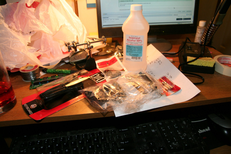
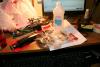
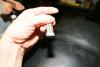
Every few posts I like to post pictures for you guys. I hope you enjoy my photography:) I do have a good camera: Canon Rebel XT DLSR with a 2.8 17-50mm lens. It can get close-up and almost take macro pictures. Of course the version you get here are reduced to 800x533. But if you want me to crop or provide higher quality, let me know. This picture is of what I just got: My 99% Isopropyl Alcohol 473ml $4 Easy to get from Kmart phramacy, I just had the pharmisist order it. It's a non prescription item, so no problem to get. I'll use that with cotton swabs to spot clean the circuit boards. My other mixture with the compressed air is good for major cleaning. But after I solder in the Midi sockets, or if I have to touch up solder joints, etc., I may just want to spot clean that area with cotton swabs. My order for 8 PCB mount midi sockets, 8 male midi connectors, and 8 panel mounts. I also decided to buy a 5 foot Shielded Midi cable from Best Buy for $6. This way I have a good cable that I can cut to make custom lengths, using the connector on one end and just adding another to the other. I should be able to get 2-3 midi cables from this. Last on my list today was fuse holders and fuses for the cores. I got .5A fuses, since that should be the max a core should draw according to the specs. A pack of 4 fuses was $2, and a pack of 2 fuse holders $2, at Radio Shack. I am NOT going to connect up and power up and test the cores without fuses! I have some cheap 9v 1A adpators for the cores. I plan to use one adpator per core for redundacy, etc. A lot of time sometimes is spent getting the hardware, etc. Plus driving around to locate stuff wears you out. Hardware does add up too(I haven't kept inventory, but I have spent at least $100-$200 for miscellanious stuff), and adds to the time of the project. But now I should have everything I need, hopefully, to finish up the keyboards. But I am sure there will be something else I may want and need too. Now to locate my LCD modules...I know I have some nice 40 character, 2 or 3 line?, back lit, ones that were never used, I ordered for some other project somewhere.
-
Thanks for the link. Saves me the time to look it up again. That was what I wanted to look up next. As soon as the Dins are wrired to the terminals I will be powering up the core and testing it. I was hoping that someone would offer my some help. I have been posting along with this thread maybe putting across that I know it all. But now I am starting to get to the point where I may be needing the help of this forum for some things. It's true that I know electronics and can look up the specs of the IC chips and the Din and core circuits etc., and figure it out. But I am also lazy and excited to get this working too, and knowing that a lot of people have it working, I am just want to see how it's done too. Plus I am getting older and my mind doesn't work as well as it did. So sometimes I just need soemone else to show me, etc. My PCB sockets, panel mounts, and male Midi connectors are also here. So nothing stopping me now other than making sure I do it right. BTW I read your post on the Miditzer forum letting people know that the Midi sockets aren't included. Yes, the PCB Midi are the way to go to have more solid connections. You can always make a Male Midi connector plug into the PCB on one end and have apanel mount on the toher if you want to relocate the Midi, etc. Unless you have a small box(synth box?) where a Midi cable wouldn't fit and you want a panel mount. Then I would use headers to panel mount. In my case: I will be having 4 cores: One will be midibox128 with 4 Dins and Douts for the stops (I plan to change those to push button with LEDS and latch circuits, etc, so the computer can control,them) and pistons, channel 0. Eventually that will be the merger core. Chanel 1 is top keyboard, chanel 2 the lower, and chanel 3 the pedal board and swell. They will be daisy chained with Midi cables to the in and out of the PCB mount Midi sockets. I may make some male-female cables too, etc. Or routed to a panel mount, etc. Acording to what specs I read on the cores, you can have the PCB and also use headers to daisy chain etc. So, as long as he designed the cores boards for PCB, why not just install them? I haven't located a nice 5 pin cable locally for the Midi cables. 3 foot Midi cables at best buy are only $2 But they are out. I had thought of buying a Midi cable and just cutting it to make more. I don't need 3 feet from one keyboard core to the other. But I may just use Cat5 or 6 conductor phone cable. Those cables are more flexible too so I can turn them in tight corners, etc., if I need to. But they are 30 gauge? I hate soldering 30 gauge! I would rather work with 22-24 gauge . They aren't shielded, but do I need shielding? Or I can make my own cables. Just take 5 22-24 gauge wires and wrap in aluminum foil and electrical tape? Then I would have shielded cable too. Up to this point I
-
Shew.. I decided to flip the Dins around so that the ribbon cables to the terminals didn't have to be twisted. So the IDC connectors wil be different(still Vs = black, but with the Dins flipped it will be to the right, where I want it). At least the connections to the switches are streight forward. I can always reverse them in the software, so that should not be a problem. I have 2 IDC that I can't use for J3-J6 now, that were already made. But I can use those for Connecting up J1 of the first Din to J2 of the second, and J1 of the second to the core. Left to right. I hope I connect the Dins together and to the Core right. Then I tried to find a picture or a schematic of Din versions 5, and core versions 4 diagram for a midibox64, etc.(Yes I looked at the Wikis), of J1-J2-J2-J9, somewhere where soemone else may have connected up keyboards for the Midibox64, but so far no luck. It's those dual inline J1/J2, and on the core J8/J9 connections I may have a problem with. Some inner and outer pins are tied together, but others aren't. I can move an IDC on a header a bit, to route inner to outer pins etc., but that isn't good. At least the 2 grounds and 2 +5v pins are both on inner and outer pins and as long as those are right(which they will be), nothing should blow. I am hoping that avishowtech didn't make it that complicated and the dins should conncect together just fine with the IDCs, etc. Well first I'll test out the core without the dins, then conenct one din at a time, test, and hope things don't blow, etc. I may have to use the 5 pin female headers eventually to connect the dins and cores to make sure it's right. I also have extra IDC connectors too, if I need to redo the 2 cables. I also need to hunt up an LCD module for testing the cores(I have some somewhere, just need to find them). I am also going to finish one keyboard and get it working right before moving onto the second. The second keyboard should be easy, since it's just duplicating what I do to the first. Then I will merge the 2 cores, etc. Ok now to finish the wiring...
-
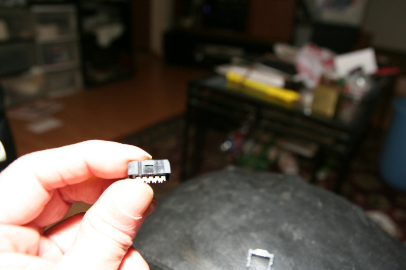
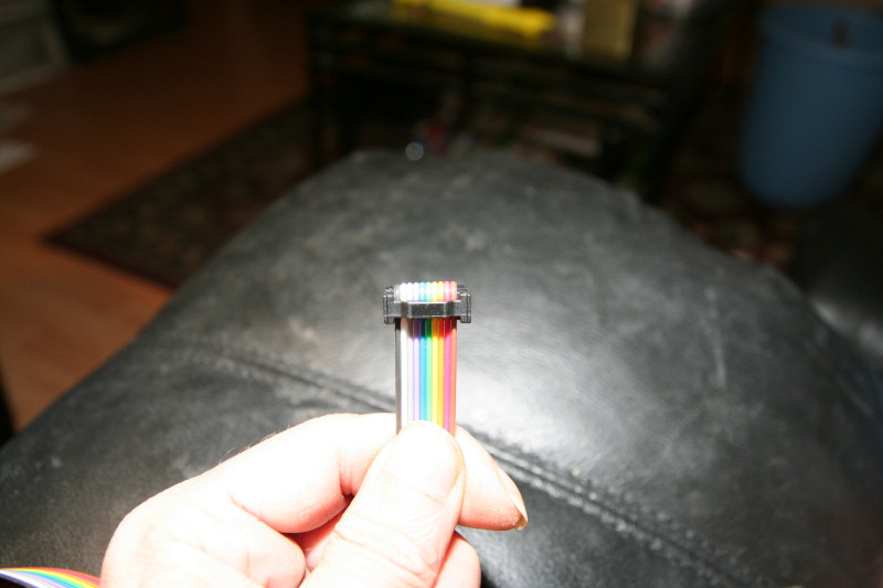
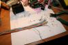
I thought I would show you the assembly of the IDC connectors to the ribbon cables. If you ordered from avishowtech.com you have the option of 10 pin female IDC or 5 pin crimp type. Version 5 Din boards(I have version 5) can use the IDC, so I choose the IDC since they are easier to assemble and cheaper, etc. If you ordered his 10 ribbon cable it is nicely colored too and starts with a brown and ends with a black colored wire. I used the brown for pin 1, and black for pin 10(so it can be color coded for the ground pin) If you use a plain grey ribbon cable, pin 1 is usually colored red. These are standard color type codes, so it's nice to try to have some standardization and consistancy. There are 3 parts to the IDC connectors. The bottom part has an arrow where pin one is to be. To be consistant this should be on top and on the right(but you can reverse it too if you want). The second part you put on first by slightly pushing it in to partly pierce and crimp the ribbon. It has ridges to aling the wires right, so they get pierced correctly. You can use your fingers for this part. Once the wires are slightly pierced, you can then insert into the vice and finish crimping it. If your vice has ridges, use a piece of sheet metal, etc., so you don't damage the connector. Center it in the vice and slowly finish crimping it together. The third piece is a strain relief and keeps the ribbon from pulling out. You insert that last, with your fingers. You can cut the ribbon with a scissors. Make sure it is at a good 90 degrees. As you can see, if you are to use the strain relief, you need to insert the ribbon cable from the other side, and bring back around. So plan accordingly. Yes, my vice is rusty, but so am I:) I had it in storage, but it works fine. If you don't have a vice, I suggest buying that instead of an expensive IDC crimpers. It can also be used for other things too. I am also a couch potato, so I like to work in the comfort of my living room if I can. Here's some pictures..

-
Today I'll be mounting the Dins and Cores to the boards and running the ribbon cables. My Midi socket order hasn't arived yet, so I am taking my time. I ordered priority mail, and they have been shipped. But it's christmass season and the mail may take longer, and this is a weekend too. But I should get them within the next couple of days Although not necessary, I am trying the keep the lengths of the ribbons from J3-J6 even to the terminals. This way all resistances of the wires will be the same (i.e. each switch will offer the same resistance to the Din's when closed). I also picked up some 1/4 inch nylon spacers to space the circuit boards from the boards. The screws to mount the barrier strips, Dins, and Cores to the boards are #6 5/8 inch pan head sheet metal screws. Long enough to go into the 5/8 inch board without going through the other side. Since there are quite a few screws, and I may use this type of screw somewhere else too, it was cost effective to just buy a box of 100. The screws to mount the terminal strips were tiny #4 5/8 inch I think, flat head brass wood screws(I'll provide a picture of them if you want). The nylon spacers are to fit #6 screws and are 1/4 inch long. Both available at Ace hardware(my hardware store of choice for special hardware) The wires to the switches are 22 gauge 50 foot?(not sure, I had them laying around) spools(available at radio shack) One red and one black so you can have them color coded for a hot and ground side. Ribbon cable wires are 24-26 gauge. So you will need a wire strippers that can go down to that. No need for expensive IDC crimpers, nor automatic wire strippers. You can use a small vice for the IDC and a regular wire strippers for the ribbon cables. Just separate the ends, and strip each end. I'll may be provide some pictures of how I do it. Since the terminal strips can handle down to 22 gauge only, I will strip the ends of the ribbon cables to 3/4 inch and bend the ends back and twist to double up the ends.
-
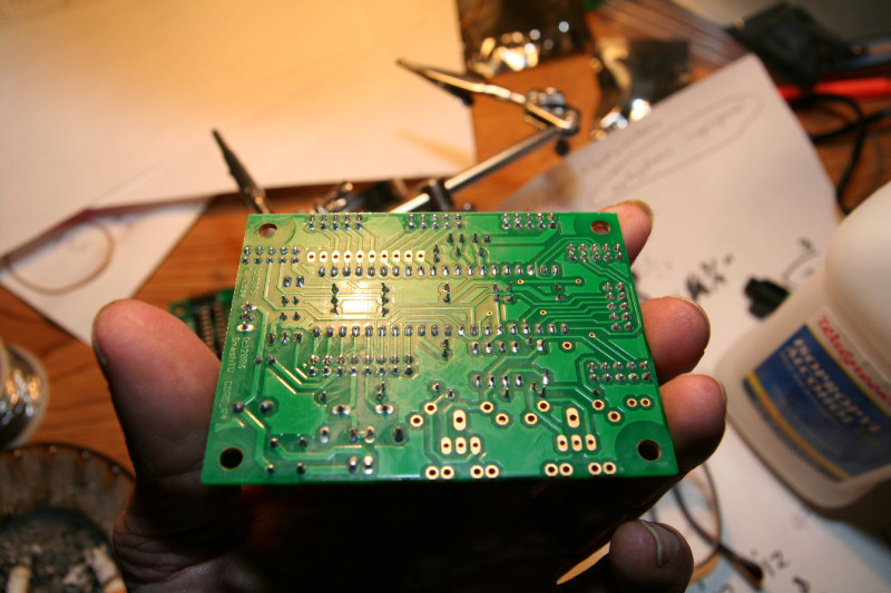
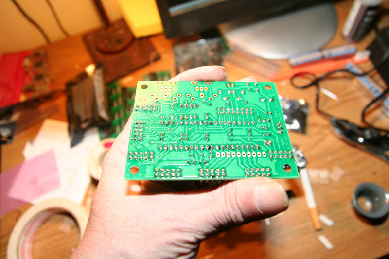
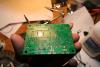
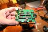
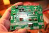
Today I decided to look for the circuit board cleaner that I used to use. The real deal is called "trichlorotrifluoroethane" Long name eh? That's what I used when I worked for Astronautics Astronautics is a Big Mitary Contract Electronics Company. They made circuits for satilites. Since these circuits were to be in space, everything had to work well. I was a Supervisor and Head Eletronics Tech in a QC Lab. I loved that Tri stuff. After cleaning a circuit board with that, they went into an ultrasonic cleaner too. But you can't get that stuff easily, so forget it. Most circuit board cleaners have one or more of the following: Acetone Keytone. Methal ethal OR other versions of alcohol. A lot of people use 99% pure Isopropyl Alcohol 99% is available, you just have the check the pharmacies. Today I searched out numberious pharmacies to try to find it. I ended up at a K-Mart pharmacy that I was able to get a Pharmisist to order for me(be in Monday) In the meantime I got 91% Isopropyl Alcohol, which is easily available at Walgreens, etc. At Walmart you can get small bottles of 100% pure Acetone(fingernail polish remover) in the nail polish area. Make sure it's 100%. Some nail polish removers are Acetone, but contain lanilin, etc. Walmart does have the pure stuff. Home Depot too, but you have to buy a $6-$10 can of it there. I like to use both together. You can also find Methal Ethal Keytone at Home Depot(a hardware store). Methal Ethal Keytone comes in a can at Home Depot. But it's $10! It can replace the Acetone, but Acetone works just as well. You could use any combination of Isopropyl Alcohol, Acetone, Methal Ethal, Keytone. I just mixed 473ml of 91% Isopropyl Alcohol($1.49 at Walgreens) and 118ml of 100% Acetone(small bottle at Walmart for $1) together. This is a cheap cleaner that works just fine. Don't buy expensive cleaners! Then I got cheap tooth brushes, and a bottle of compressed air (available at most office supply places, used to clean computer keyboards, I got a 10oz bottle for $6.00 at K-Mart in the audio/video area). Using my mixture and a tooth brush: I cleaned the circuit boards and blew them off imediately before they dried with the compressed air. You can also use Q-tips for spot cleaning too. If your board is sticky, you didn't clean it well, but you can always reclean it until it's clean. You need to clean until it sparkles:) My mixture worked OK. But the 99% Isopropyl Alcohol would work better. Here's a picture of a cleaned core board. It's sparkly clean! Only by cleaning it could I tell if there were any solder bridges, etc.(the flux hides that). You can't see it well, without using the Lope, but my solder joints are good and what solder whiskers there were, were cleaned off. No solder bridges, etc. My soldering is good, but if your's isn't: A solder bridge is where you have solder going from one pad to another etc. If you get one, don't use solder braid to remove it if you can. Either use a solder sucker, or desoldering iron. Just by touching the iron to the solder pad or lead end and sucking it imediately should remove it. You may want to put a drop of solder flux on it first, if you already cleaned your board, to help it flow better. Solder braid can destroy circuit boards if you aren't careful. So solder braid is a last resort to remove a ton of solder. If you use solder braid use solder flux on the braid, etc., to help the solder to flow better. I can't tell you where I got my flux. But it should be readily available. Put a drop on the braid and it will work better. Whiskers can happen too but usually are just stuck to the flux, and by removing the flux you remove the whiskers, etc., that are stuck to the flux. Flux is sticky and needs to be cleaned off, else the flux from the solder can make small solder whiskers, etc., stick to the board, causing shorts, etc. Later on too, the flux can collect debry, that can short. So it's always good to clean the boards well after soldering. Surfacemount boards are a whole different story. I would share my tricks for those too, but I am not doing that type right now... But this is how this type of board is soldered and cleaned. With the right tools and the right technic, it is easy to do and you too can have high quality boards. So I hope you are taking notes on all you may need too before you start, so you don't have to hunt for them once you start. Get a Lope, it is great for inspecting your work. I can't tell you where I got mine. I had it for years. But I think I saw them at American Science and Surplus(I think they have a web site, The main store is located here though in Milwaukee, Wisconsin, USA)
-
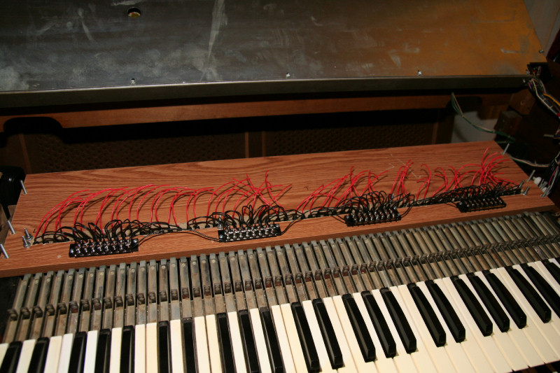
As promised, more pictures! I decided to connect up the hot side wires from the switches to the terminal points first, once I had the wiring from the dins figured out to the terminal points. That way I could test out the switches first. What took me so long was that: 1. I had to readadjust the terminal strip moutings as I connected up the wires from the switches. I initially I started out with mounting them evenly at 3/4 inch apart. But the spacing of the switches is different than the spacing of the terminal points. So as I connected from left to right I would get short with wire length. Plus I had to use the spare terminal points to help. I ended up with .75" before and after first strip(I start measuring from first switch), 1.5" between second and third, and .75" from there on to the right. After the 4th group of 10 points(first din ending), I skipped 4 more points to add spacing. Those were the 4 spare I had to spare. So it works well with just enough wire length from the switches to the terminal points. Maybe I shouldn't have trimmed the 1 1/2inch from the hot side? Oh well, it still works out. 2. I had to adjust the spacing from the keyboard hammers to switches to get better contact. I initially did an electrical check on all switches before soldered the wires onto them. But I wanted to test them again once they were conencted up to the terminals. So I did an electrical check to make sure all switches and keys worked fine. 1 switch was bad(luckily I made it easy to replace, and I DO have a few spares)! Already? It must have went bad with the soldering or something? I hope these switches would last. Damn Radio Shack China crap! Oh well... Next I will connect up the dins with the ribbon cables to the terminal strips. Yes, electrical testing of those too. I am planning the electrical tests in a certain order as I go. This way if there is a problem with the dins or cores, at least I know that the switches are good, etc. Here's the pictures.

-
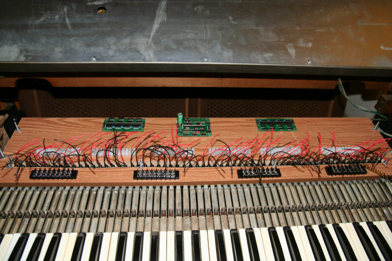
I had to get some sleep, but I'll be back at it shortly. EVERYTHING IS GOING AS PL;ANNED NOW. I just called about my Midi socket order and it's on it's way! It's only being shipped from California to Milwaukee Wisconsin USA. I live in a big City, so shipments get to me fast once shipped, because I am not far from the airport, where the Freight planes land. Priority mail usually gets to me next day! So by the time they get here I'll be ready for them. I am still thinking out how to route the ribbon cables to make them neat... It's too bad that there are 4 groups of 10, or 40 wires out. I tried to compensate for 32 wires and 4 extra to the terminal points, but didn't account for the other 4. I don't like to strip out one extra length from the ribbon cable for the grounds to route over the terminal strips to the barier strip. I don't want hanging wires either, they need to go to a connector somewhere. I was hoping to attach to a terminal point and then from there to the barier for the grounds. So I am debating upon adding more terminal points... OK, decided! I'll add one more terminal strip of 12 terminal points. I only need 4 more per din = 8 more total, which gives me 4 spare. Nice to have spare points too just in case I want them for something. There will now be 7 terminal strips, and 4 barier strips, and they all should fit fine. So now to remeasure and remount the terminal strips.. Heres is the plan for the new ribbon wiring to the terminals: All 10 wires per header of J3-J6 will go to a terminal point. On the switch side I will skip every 9th and 10th point. Every 10th point is a ground, which can have a wire on the switch side of the terminal point wired over to a barrier point for ground. I don't need to wire all 4 ground points, just one per Din to the barier. I'l pick one that routes over nicely to a spare barier point (remember that I left 2 spare barier points just for this?). No hanging wires! Every wire will be conencted to a termianl point! More pictures soon..
-
OK. I have the ribbon cable wiring from the dins to the terminal strips figured out: My Din boards are version 4, with dual inline header pins for J3-J6. 4 header groups of 10. Pins 1-8 of each group are your digital inputs from the switches. Pin 9 is no contact. Pin 10 is Vs(ground). The colored ribbon cables I have end with a black colored wire at one end. So to keep with black=ground, that end will go to header pins 10. There are 4 grounds and 4 no contacts. Each group of 3 terminal strips of 12 terminal points equals 36 points. If each Din handles 32 contacts, 4 non contacts, and 4 grounds for J3-J6. That's 40 wires out! I want every wire to go somewhere and be connected, so: For each header pins 1-9 go to a terminal point. On the switch side every 9th terminal point gets skipped (no contact wire on other side from din). Pin 10(ground), will just be longer and go to the barier strips. BTW I don't use an IDC crimper. I use a small vise. Works well... I'll post pictures as soon as it's wired up to the dins.
-
OK. Terminal strips are screwed to the board, along with the dins(I just put a couple of screws loosely into the board, later I will add spacers and tighten them, etc.). Each din is centered in the middle of each set of 3 terminal strips, and in 3/8 of an inch to allow for, possibly, covers later. All parts are screwed to the board with wood screws Don't forget to drill pilot holes before you screw the screws in, else you will not be able to. I also trimmed the hot wires(red) from the switches back 1 1/2 inches so they are not so long (but long enough to compensate for wiring changes if need be). Next I will plan out the ribbon cables to neatly go to the terminals. I won't connect up the hot wires from the switches to the terminal strips until I have the dins wired to the terminal strips first. This is because I don't know where yet the grounds from the dins will be. If they end up in the middle, then on the switch end I will skip those terminal pins, so the grounds can go from dins to the terminal strips and then to the barier strips. You will see what I mean later. I will now crimp the IDC connectors onto the ribbon cables and look at the schematic again for the dins to see what gos where, etc.
-
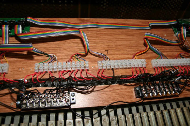
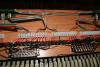
OK. The grounded side of the switches are done. I had just enough length with the wires! I connected 2 wires per terminal point from left to right, skipping 2 in the middle 2 barrier strips to ground the dins, and possibly the cores to. The last terminal on the last barrier strip has 3 wires, else all others have just 2. 15x2=60, and there is an ood 61 wires for the keyboards, so I had to do 3 for the last point, to give me 2 open ones to conenct the din and core grounds to. I didn't tin the ends yet(that will be done later). The ends are just stripped about 1/2 inch and twisted together around the screws. I am not going to use lugs, I will just insert the tinned ends under and around the screws later. FYI Since each din can handle 32 keys/switches, and I want all 61 keys/switches in sequence: The first din will have the first 32 keys/switches, and the second din will have the last 29. But I can easily change that if I want to just by reconnecting to different terminal points. As I write this thread, I am kind of thinking out loud, giving you my thought processes as I go. This not only may help you with your thought processes on your projects, but it also helps me to see my thoughts better so I can maybe see where I may have to change it, etc. Pictures also speak out louder than words. So I am also trying to provide you with plenty. I hope that with this thread you can actually see what it takes, from someone actually doing it and showing you. If I make mistakes, I will share them so you can avoid them, and not make the same ones (i.e. learn from my mistakes). So I hope I am helping you out too. If you have any suggestions, or question why I am doing something a peticular way, that I haven't shared why, and you want to know why: Feel free to chime in. It may help me too, to also change it, if you have a better way to do it.
-
OK. After measuring the distance from a switch wire to the barrier strips, I had to add another barrier strip for the switch wires to all reach a terminal point. So I'll be using 4 barrier strips of 8(4x8=32), so that's 32 terminal points. 32 x 2=64, so now I only have to wire 2 switch wires to each terminal point, and still have 3 spare. I am being conservative with the barrier strips, but just enough so. Sometimes you try to plan ahead, but don't really know until you start to put things together on how it will work out. I knew that 4 inches of wire from the switches should cover my lengths. I knew that one side of the switches were all grounded, so they can be grouped together, so no need for a terminal point for each switch. I bought 6 barrier strips(3 per keyboard) figuring 3 wires per contact should work. But with only 3 barrier strips per keyboard some wires wouldn't reach. But I only need to buy 2 more! Now I will strip the ground ends of the switch wires and connect them to the barrier strips. Check on the placements before mounting the barrier strips to the board. Later I will trim the wire lengths to make it more tidy. I am glad I decided to use terminal strips and barrier strips instead of soldering everything together. I will thank myself when I may have to change the wiring around a bit if I need to. Plus if a switch needs replacing it will be easy to do: Disconnect from terminal strip and barrier strip, unscrew switch from mount, and replace! The keyboard switches are bound to fail (years of hitting the keys many times will eventually wear out the switches). So easy replacement should be a factor.

-
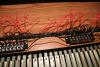
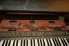
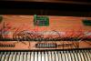
Here's a couple of pictures for you guys. I am thinking out my placements right now. I want the core in the middle, I think. I have just placed my terminal strips, barrier strips, and circuit boards on my keyboard board. The terminal strips come in groups of 12 contacts. I have 6 per keyboard(12x6=72) I only need 61, so I have a few spare contacts. One end of a contact gos to a switch wire, the other to the ribon cables that go to the dins. These handle down to 22 gauge, but the 10 conductor ribbon cables that go to the dins are 24-26 gauge. So I'll have to double up the ribbon ends and tin them. The barrier strips come in groups of 8 contacts. I have 3(8x3=24). Which means I will wire 3 wires from the switches to each of these contacts(60/3=20+1=21, so there are 3 spare contacts, which will go to the 2 dins and also to ground)). These all are grounded so they can all be connected together. I also have jumper strips to make it easier to jump them all together.
-
I found this online source that ships Priority mail to order my Midi sockets from: http://www.action-electronics.com/ppdin.htm I was also able to call and talk to a person, to make sure they are in stock and will ship tomarrow. That's important too when ordering online. I decided to just do the PCB mount Midi type sockets (for now, I'll see when they arrive which route I want to take). I ordered 8 of those and 8 chasis mount, along with 8 5 pin male connectors. They didn't have the shielded PCB mounts in stock, which I wish I could have got instead, but I'll do shielded cables though. That way I can make up my mind when they get here, plus have some spare chasis mounts in case I want them somewhere. Price wasn't bad and they will be shipped out tomarrow. With the 5 pin male connectors, I can also make my own Midi cables. I just have to get some 5 conductor cables(shielded if I can), which should be easy to get locally. With the PCB mounts instead of headers to chasis mount, the connections may be more solid The 1 or 2 pin header connections to chasis mounts, etc., may come off of headers easier than having a nice 5 pin PCB mount midi type connection right on the boards. This way I am assured of decent connections from one core to another, etc. But I also have chasis mounts in case I want them elsewhere and just run a cable to them, etc. I have choices now and can decide when the parts get here. Hopefully I will get these in a few days max, and by then be ready for them. So back to work with being able to relax on that part. In the meantime I can get everything else done. I hope I have helped some of you that are thinking of ordering, to make sure you have everything you need.
-
Well, I do have a few suggestions for avishowtech(you can pass it on to him, or I may try): #1 He includes JUST ENOUGH headers for the circuits. You also have to break them away from long strips. If you aren't careful when breaking away a group of 10, as I wasn't for a couple, you end up having to try to piece them together. Luckily I had enough spare din kits that I was able to use some header strips from those to get 4 good dins. I'll have to order some header strips to make it up. Plus, the 16 pin header for the core requires you to break away a group of 10 and a group of 6 to make it a 16 pin din(dual in line) header. You need to trim them to fit together right. So a few extra din header strips would be nice. I know that he is trying to cut costs by just providing enough. But any good supplier when it comes to kits usually includes a few extra pieces just in case. Headers are not that much to just put in 1 or 2 extra strips. #2 I assumed that when I ordered the core kits with the preprogramed PICs that the whole kit was complete with the midi sockets. So he should make it a little more clear that you need to add those even if you ordered the kit with the PIC. He allows you to choose the program for your PIC. He should also have a feature to pick out the sockets you want to add too. Since it is a whole kit it should have the sockets or a check box for or without them etc. Those types of parts are hard to get locally, so that should be more clear so you are assured to have them. I went all over Milwaukee yesterday trying to locate those sockets, and I have a big city with plenty of Electronic and Musical Instrument Supply places. I couldn't find them anywhere. But I did find a guy that had non PCB 5 pin female Midi type D-Subs connectors. So I'll have to order them online. Hopefully I can get them next day. I hate when I am working on a project to be just about there, and not be able to finish because of missing parts. In the meantime I'll plan how to mount the dins and cores and conenct them up. #3 In his next revision of the core circuit boards, he should space the holes for C1,C2 a bit farther apart so they can fit easily side by side. Or provide smaller versions of those caps if he can. So to answer your question: No there are no spare header pins. But you gave me a thought! I could just use a few non PCB mount female 5 pin D-Sub(midi) connectors, and plug them into headers. I only need one to connect to one of the cores to go to the computer. Fortunetly I have spare headers that I can use for now from my other kits. So I can use headers and make my own cables to daisy chain the cores, and then the core that gos to the computer will just have a non PCB mount plugged into the headers! My problem solved! Plus midi cables are expensive, unless you made your own, and it would be a pain to make ones just the right length for inside of the organ (I only need a 1 foot midi cable ton daisy chain from one keyboard's core to the other). 5 or more conductor cable is cheap. The male connectors may also be hard to get. I'll just get a few female header connectors(those I can easily get too locally). Today I'll go get those females from the guy that has them locally! I'll order PCB mounts just in case too and the make up my mind later which route to go. But I stil like the idea of the PCB and proper midi cables for good conenctions. I need to decide before I solder either the headers or PCB onto the cores. I'll update this thread later today with my mounting of the dins, cores, and connecting up of the switches. Hopefully by the time that part is done, I'll have those midi sockets.
-
I guess I did:) But I wanted to document it for my own too. Anyway, I am finished soldering except for the midi connectors. But avishowtech didn't include the midi sockets! I just read that they aren't included, damn! Now I'll have to locate some locally!
-
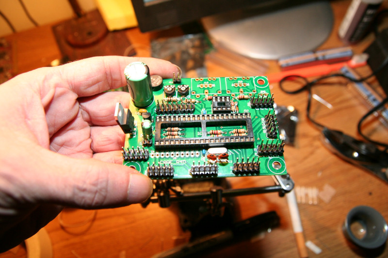
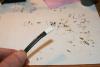
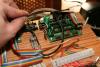
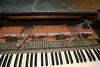
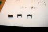
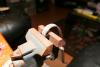
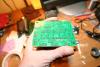
Here's what I just finished soldering. C1,C2 were tricky since they were a bit big for the hole spacing, so I had to bend them slightly so they wouldn't touch each other. The IC sockets are next.
-
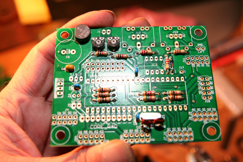
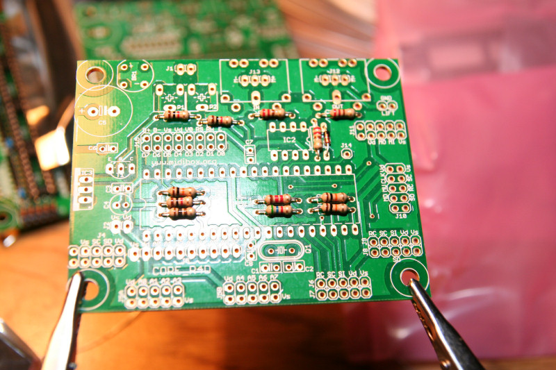
IT looks like the cores are a bit trickier. I'll have to start with the resistors inside of the IC socket, and do the resistors first, then Ic sockets, etc. I'll work up from lower level components to higher. OK. Resistors and D1 first: