Underskor
-
Posts
24 -
Joined
-
Last visited
Underskor's Achievements
MIDIbox Newbie (1/4)
0
Reputation
-
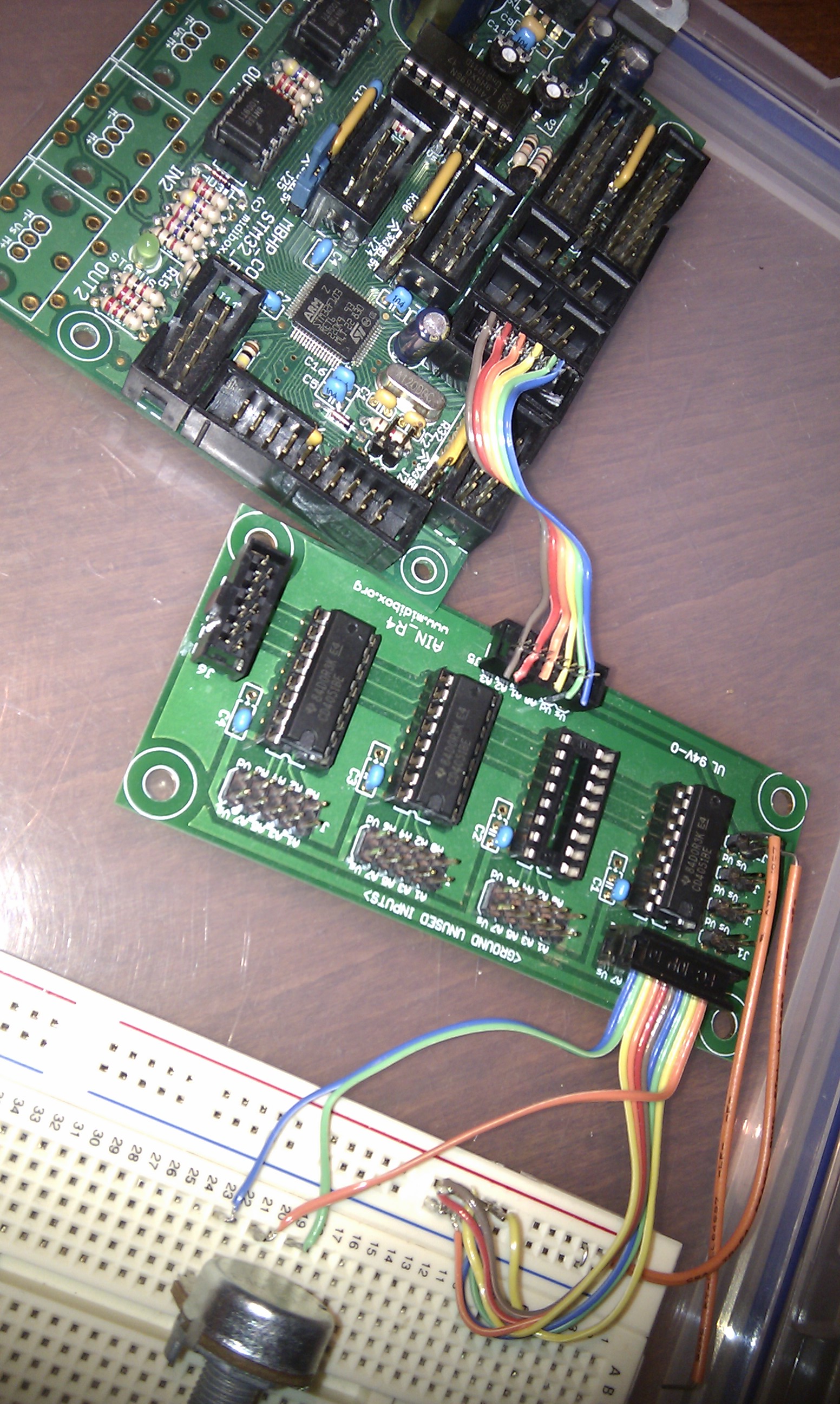
Success! Sidmonster was on the right track but I remade the wrong cable. >_< After much help from SmashTV (he's going to hate me for this), it turns out that the culprit was this guy: It was connecting the mux control lines from the Core to the AIN, and 2 of the pins was slightly bent and had not broken through the cable and made a connection, which is why my control lines were only ever set to Low/Low/High and stuck reading J1.A5, not reading the single pot I had connected at J1.A0 (I think). To read the pot, I forced the lines on AIN.J6 to High/Low/High (A to Vd, B to Vs, C to Vd) which corresponds to pin 5 of the 4051 (as seen in datasheet - page 4 truth table). Pin 5 of the 4051 is J1.A0 - my pot! Looks to be working! Very happy. Big thanks to SmashTV and the guys on #midibox, it was all them. Hope this thread helps someone out one day!
-
At my wits end here, spent the last few nights trying different things but I can't get anywhere. Removed all 4051s but J5.A0, and grounded AIN:J5.A1-A3 Reflowed all AIN joints. Been over the board with a magnifying glass, scraped/brushed between connections cleaned to make sure there were no rogue solder trails (it was light - didn't damage traces) Removed breadboard from the equation. Still getting a large, constant stream of jitter. I am also now getting an "Unrecognised USB device - device has malfunctioned" tooltip on windows XP which I wasn't getting before, however if I use the J27 jumper and load the Bootloader, this notification does not occur. Here is an extract of the jitter so you can get an idea of the volume (if that's relevant): [4598.587] APP_AIN_NotifyChange(6, 63) [4598.588] APP_AIN_NotifyChange(0, 75) [4598.588] APP_AIN_NotifyChange(2, 65) [4598.588] APP_AIN_NotifyChange(4, 71) [4598.588] APP_AIN_NotifyChange(6, 65) [4598.589] APP_AIN_NotifyChange(0, 70) [4598.589] APP_AIN_NotifyChange(2, 64) [4598.589] APP_AIN_NotifyChange(4, 69) [4598.589] APP_AIN_NotifyChange(6, 63) [4598.590] APP_AIN_NotifyChange(0, 75) [4598.590] APP_AIN_NotifyChange(2, 65) [4598.590] APP_AIN_NotifyChange(4, 71) [4598.590] APP_AIN_NotifyChange(6, 65) [4598.591] APP_AIN_NotifyChange(0, 70) [4598.591] APP_AIN_NotifyChange(2, 64) [4598.591] APP_AIN_NotifyChange(4, 69) [4598.592] APP_AIN_NotifyChange(0, 69) [4598.592] APP_AIN_NotifyChange(6, 63) [4598.593] APP_AIN_NotifyChange(0, 75) [4598.593] APP_AIN_NotifyChange(2, 65) [4598.593] APP_AIN_NotifyChange(4, 71) [4598.593] APP_AIN_NotifyChange(6, 65) [4598.594] APP_AIN_NotifyChange(0, 70) [4598.594] APP_AIN_NotifyChange(4, 69) [4598.595] APP_AIN_NotifyChange(0, 69) [4598.595] APP_AIN_NotifyChange(2, 64) [4598.595] APP_AIN_NotifyChange(6, 63) [4598.596] APP_AIN_NotifyChange(0, 75) [4598.596] APP_AIN_NotifyChange(2, 65) [4598.596] APP_AIN_NotifyChange(4, 71) [4598.596] APP_AIN_NotifyChange(6, 65) [4598.597] APP_AIN_NotifyChange(0, 70) [4598.597] APP_AIN_NotifyChange(2, 64) [4598.597] APP_AIN_NotifyChange(4, 69) [4598.597] APP_AIN_NotifyChange(6, 63) [4598.598] APP_AIN_NotifyChange(0, 75) [4598.598] APP_AIN_NotifyChange(2, 65) [4598.598] APP_AIN_NotifyChange(4, 71) [4598.598] APP_AIN_NotifyChange(6, 64) [4598.599] APP_AIN_NotifyChange(0, 70) [4598.599] APP_AIN_NotifyChange(2, 64) [4598.599] APP_AIN_NotifyChange(4, 69) [4598.599] APP_AIN_NotifyChange(6, 63) [4598.600] APP_AIN_NotifyChange(0, 75) [4598.600] APP_AIN_NotifyChange(2, 65) [4598.600] APP_AIN_NotifyChange(4, 71) [4598.600] APP_AIN_NotifyChange(6, 64) [4598.601] APP_AIN_NotifyChange(0, 69) [4598.601] APP_AIN_NotifyChange(2, 63) [4598.601] APP_AIN_NotifyChange(4, 75) [4598.602] APP_AIN_NotifyChange(0, 71) [4598.602] APP_AIN_NotifyChange(4, 69) [4598.603] APP_AIN_NotifyChange(0, 69) [4598.603] APP_AIN_NotifyChange(4, 74) [4598.604] APP_AIN_NotifyChange(0, 70) [4598.604] APP_AIN_NotifyChange(4, 69) [4598.605] APP_AIN_NotifyChange(0, 75) [4598.605] APP_AIN_NotifyChange(2, 65) [4598.605] APP_AIN_NotifyChange(4, 71) [4598.606] APP_AIN_NotifyChange(0, 69) [4598.606] APP_AIN_NotifyChange(2, 63) [4598.606] APP_AIN_NotifyChange(4, 75) [4598.607] APP_AIN_NotifyChange(0, 71) [4598.607] APP_AIN_NotifyChange(4, 69) [4598.608] APP_AIN_NotifyChange(0, 69) [4598.608] APP_AIN_NotifyChange(4, 75) [4598.609] APP_AIN_NotifyChange(0, 71) [4598.609] APP_AIN_NotifyChange(4, 70) [4598.610] APP_AIN_NotifyChange(0, 69) [4598.610] APP_AIN_NotifyChange(4, 75) [4598.611] APP_AIN_NotifyChange(0, 71) [4598.611] APP_AIN_NotifyChange(2, 65) [4598.611] APP_AIN_NotifyChange(4, 70) [4598.612] APP_AIN_NotifyChange(0, 69) [4598.612] APP_AIN_NotifyChange(6, 63) [4598.613] APP_AIN_NotifyChange(0, 75) [4598.613] APP_AIN_NotifyChange(4, 71) [4598.613] APP_AIN_NotifyChange(6, 65) [4598.614] APP_AIN_NotifyChange(0, 70) [4598.614] APP_AIN_NotifyChange(4, 69) [4598.615] APP_AIN_NotifyChange(0, 69) [4598.615] APP_AIN_NotifyChange(2, 64) [4598.615] APP_AIN_NotifyChange(6, 63) [4598.616] APP_AIN_NotifyChange(0, 75) [4598.616] APP_AIN_NotifyChange(2, 65) [4598.616] APP_AIN_NotifyChange(4, 71) [4598.616] APP_AIN_NotifyChange(6, 65) [4598.617] APP_AIN_NotifyChange(0, 70) [4598.617] APP_AIN_NotifyChange(2, 64) [4598.617] APP_AIN_NotifyChange(4, 69) [4598.617] APP_AIN_NotifyChange(6, 63) [4598.618] APP_AIN_NotifyChange(0, 75) [4598.618] APP_AIN_NotifyChange(2, 65) [4598.618] APP_AIN_NotifyChange(4, 71) [4598.618] APP_AIN_NotifyChange(6, 64) [4598.619] APP_AIN_NotifyChange(0, 70) [4598.619] APP_AIN_NotifyChange(2, 64) [4598.619] APP_AIN_NotifyChange(4, 69) [4598.619] APP_AIN_NotifyChange(6, 63) [4598.620] APP_AIN_NotifyChange(0, 75) [4598.620] APP_AIN_NotifyChange(2, 65) [4598.620] APP_AIN_NotifyChange(4, 71) [4598.620] APP_AIN_NotifyChange(6, 64) [4598.621] APP_AIN_NotifyChange(0, 69) [4598.621] APP_AIN_NotifyChange(2, 63) [4598.621] APP_AIN_NotifyChange(4, 75) [4598.622] APP_AIN_NotifyChange(0, 71) Here's the relevant code. #ifndef _MIOS32_CONFIG_H #define _MIOS32_CONFIG_H #define MIOS32_AIN_CHANNEL_MASK 0x000f #define MIOS32_AIN_OVERSAMPLING_RATE 1 #define MIOS32_AIN_DEADBAND 31 #define MIOS32_AIN_DEADBAND_IDLE 127 #define MIOS32_AIN_IDLE_CTR 3000 #define MIOS32_AIN_MUX_PINS 1 #define MIOS32_AIN_MUX0_PIN GPIO_Pin_4 // J5C.A8 - 4 #define MIOS32_AIN_MUX0_PORT GPIOC #define MIOS32_AIN_MUX1_PIN GPIO_Pin_5 // J5C.A9 - 5 #define MIOS32_AIN_MUX1_PORT GPIOC #define MIOS32_AIN_MUX2_PIN GPIO_Pin_0 // J5C.A10 - 0 #define MIOS32_AIN_MUX2_PORT GPIOB #endif extern "C" void APP_AIN_NotifyChange(u32 pin, u32 pin_value) { // toggle Status LED on each AIN value change MIOS32_BOARD_LED_Set(1, ~MIOS32_BOARD_LED_Get()); // convert 12bit value to 7bit value u8 value_7bit = pin_value >> 5; // send MIDI event //MIOS32_MIDI_SendCC(DEFAULT, Chn1, pin + 0x10, value_7bit); //Send debug message MIOS32_MIDI_SendDebugMessage("APP_AIN_NotifyChange(%u, %u)", pin, value_7bit); } Pictures: http://dl.dropbox.com/u/1907812/Images/IMAG0302.jpg http://dl.dropbox.com/u/1907812/Images/IMAG0301.jpg
-
Ah my mistake, I was reading the pin numbers in place of the binary columns (for lack of better words). J5A.A0 - 1 J5A.A1 - 2 J5A.A2 - 3 J5A.A3 - 4 J5B.A4 - 5 etc instead of J5A.A0 - 1 J5A.A1 - 2 J5A.A2 - 4 J5A.A3 - 8 J5B.A4 - 16 etc Thanks for both of your replies. :) Obvious after all!
-
0x000f in decimal/base10 is 15. The reason I ask is because I'd like to disable all but the first mux (J5A.A0) so I only need to ground 7 inputs while troubleshooting/configuring.
-
Might be really obvious but it's not clicking for me. // bit mask to enable channels // // Pin mapping on MBHP_CORE_STM32 module: // 15 14 13 12 11 10 9 8 // J16.SO J16.SI J16.SC J16.RC J5C.A11 J5C.A10 J5C.A9 J5C.A8 // 7 6 5 4 3 2 1 0 // J5B.A7 J5B.A6 J5B.A5 J5B.A4 J5A.A3 J5A.A2 J5A.A1 J5A.A0 // // Examples: // mask 0x000f will enable all J5A channels // mask 0x00f0 will enable all J5B channels // mask 0x0f00 will enable all J5C channels // mask 0x0fff will enable all J5A/B/C channels // (all channels are disabled by default) #define MIOS32_AIN_CHANNEL_MASK 0x0000 If 0x000f is 15, how does that relate to J5A.A0..A3? Thanks in advance, Tom
-
Have been away for a while, exams and stuff. Back into it now though. Clamped the cable down and set the mux control lines up. http://dl.dropbox.com/u/1907812/Images/IMAG0297.jpg Now unable to get any activity, even jitter from floating inputs. Still not 100% on how to do this: Anything I can try?
-
Anyone? :(
-
Hi there, I am running an AIN module from Core32, with a single pot connected. I have the AIN_CHANNEL_MASK set to 0x1, and the remaining 7 AIN inputs on the first 4051 grounded. When the pot is adjusted, MIOS Studio reports no activity (APP_AIN_NOTIFYCHANGE() includes debug message listing pin + value). Touching pins on J5C causes jitter activity. Touching pins on AIN:J5 also causes activity. Letting the pot's 4051 input float causes jitter as expected. SmashTV instructed me on #midibox to force the ABC mux control lines to 001 (A>Vd, B+C>Vs) and testing that pin 3 and 13 of the 4051 read the same (unsure how to do so, multimeter on Vs & pin 3/13, or on AIN input 1 and pin 3/13?) Have swapped a couple of 4051s in and out with no change. Note: attached pic was taken before setting up the mux control lines. Hope you guys can help :) Thanks, Tom
-
Hi there, What would be the best way to handle several VU meters? Say I am using Traktor to output VU Meter information as CC values for decks A, B, C, D and Master, both left and right channels. That's 10 meters, and depending on the LEDs per meter, almost 80 LEDs. I could use a BLM, but is there an easier way that doesn't use up almost all of my DOUTs? Arduino-powered breakout board with a shift register for each meter? Is it possible to output 0-127 values with MIOS32? I will admit I am intimidated by the idea of a BLM haha. Also, I have a (probably silly) question which I think is related to MIDI throughput. Remembering that I would like to output CC values for 10 VU meters, I have done so for a single meter and, to me, it seems like a lot of MIDI action is going on. Multiply this by 10 and I'm wondering if it would cause responsiveness issues. I am still only at the very start of the controller design stage so I just want to make sure I don't design anything that's impractical. :) I don't have it all connected at the moment so I can't give you a copy of the log to work out bytes/sec etc. :( I had a quick google around for MIDI throughput and only found something from 2001 which said it was something like 3.2kb/s. I don't think I totally understand that figure, or if it's relevant when I'm using MIDI over USB. :S Thanks, Tom
-
Thanks Tim, I had previously had it connected similar to my DIN boards as that was the only way I was getting any LED activity (not a very good troubleshooting method, I'll admit :blush:). Thanks TK! When I read that, I remembered skimming across something about that on the DOUT pin table wiki page. Seems to be working OK, haven't done much testing though. Thanks again!
-
Check out the MidiFighter by DJTechTools. It's compact, has a few buttons (custom ones can have knobs I believe?), and isn't that expensive. :)
-
The cables are short, maximum 10cm. Are these the correct resistor networks? (I don't have a multimeter on me at the moment) 4116R LF 1-221 _ _ C1019 (_ are symbols I cannot type)
-
Thanks Tim, Checked all the things you said, no luck so far, thought I couldn't find anything on how to terminate the DOUT chain? Thanks
-
I have a DOUT board connected to a Core32 board along with a DIN board and I'm getting some weird behaviour. Basically, the only way I can get the DOUT LEDs to work is by physically touching the pin of DOUT IC1 which connects to DOUT J1:S0 (I can even do it by hovering my finger close to said pin). When I do this, all connected LEDs light up, but still do not respond to the MIOS32 PinSet function. Sometimes, during startup, all connected LEDs will turn on for a few seconds and then all off. extern "C" void APP_DIN_NotifyToggle(u32 pin, u32 pin_value) { MIOS32_BOARD_LED_Set(1, ~MIOS32_BOARD_LED_Get()); MIOS32_MIDI_SendDebugMessage("APP_DIN_NotifyToggle(%u, %u)", pin, pin_value); MIOS32_MIDI_SendDebugMessage("1-Pin0: %u", MIOS32_DOUT_PinGet(0)); MIOS32_DOUT_PinSet(0, pin_value); MIOS32_MIDI_SendDebugMessage("2-Pin0: %u", MIOS32_DOUT_PinGet(0)); } When I toggle the DIN button, the Core32 Status LED toggles, and I get the following in MIOS Studio terminal, but I get no DOUT LEDs functioning. [94518.016] APP_DIN_NotifyToggle(0, 1) [94518.016] 1-Pin0: 0 [94518.016] 2-Pin0: 1 [94518.245] APP_DIN_NotifyToggle(0, 0) [94518.245] 1-Pin0: 1 [94518.245] 2-Pin0: 0 What have I missed? I've tried a couple of DOUT boards, checked for shorts on both, popped IC1 out and then put it back in, and made up a new ribbon cable connecting J8 and DOUT:J1 - no luck :(
-
Well it works, somehow! Unfortunately though I think I came home after a few drinks and poked around looking for shorts, so I don't remember exactly where it was. Thanks a lot for your help julienvoirin!