

artyman
-
Posts
104 -
Joined
-
Last visited
-
Days Won
2
Content Type
Profiles
Forums
Blogs
Gallery
Posts posted by artyman
-
-
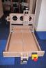
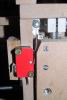
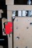
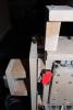
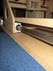
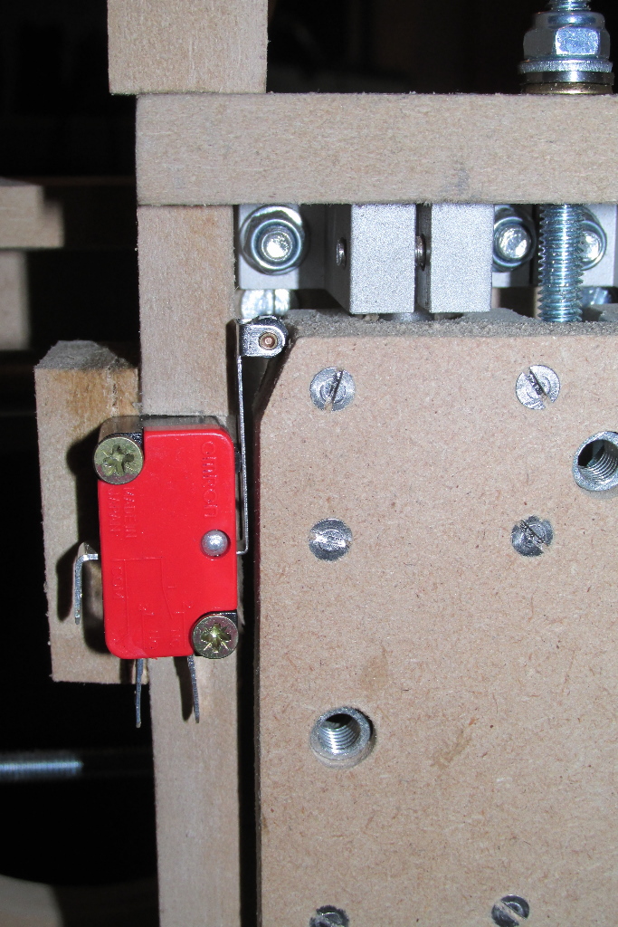
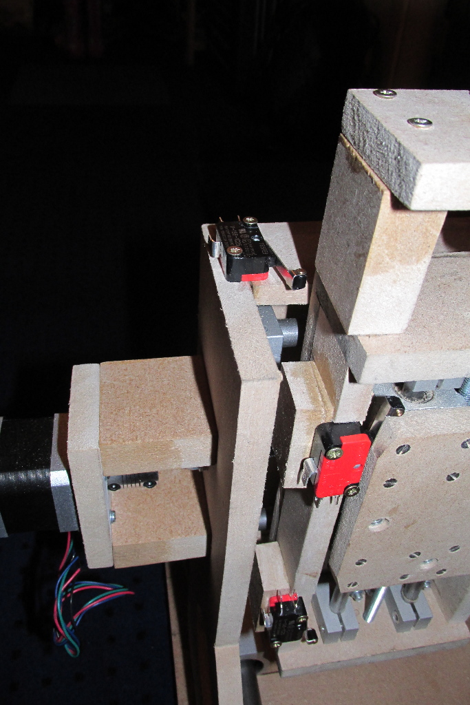
Now that I have the microswitches, and the E Stop switch, it's time, with a little help from my daughter, to fit those.
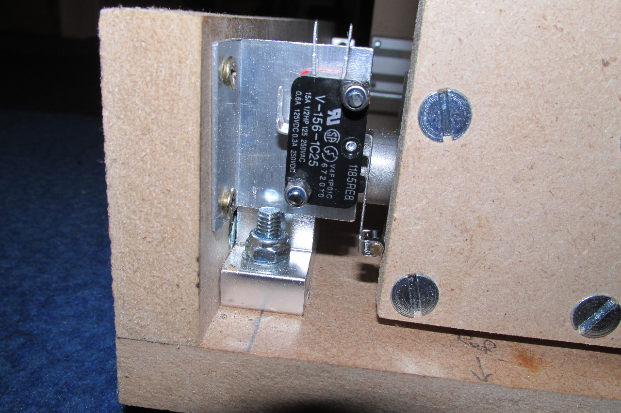
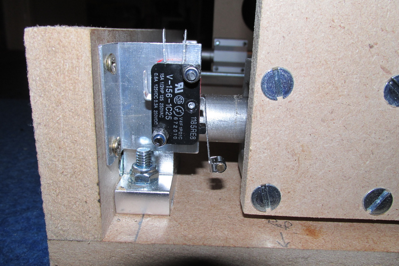
The X and Y axes were an easy fit, One set screwed directly to the structure, and the other needed just a simple L-bracket to fit.
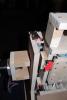
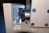
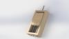
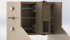
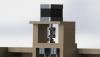
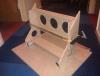
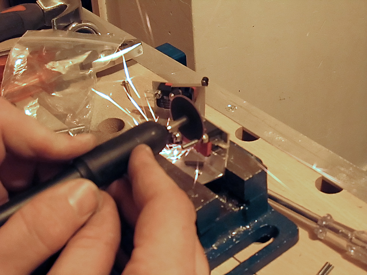
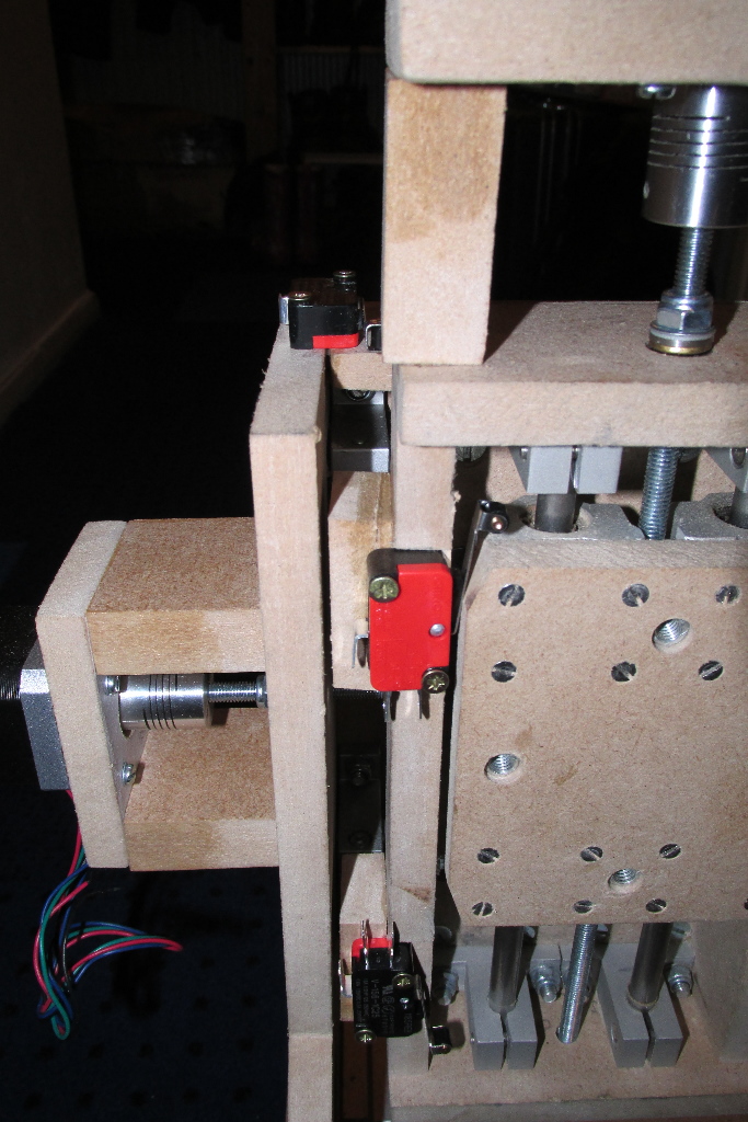
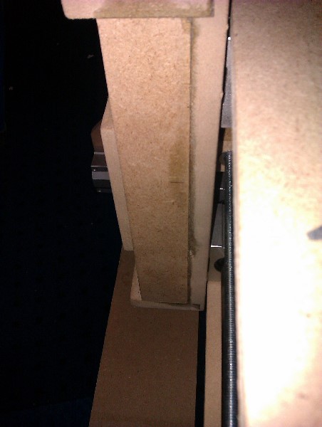
The Z axis, however was a bit more challenging. Although I got subminiature microswitches, they were too wide for direct actuation as the other axes are arranged, so a little inventive thinking was called for.
As I had roller actuators, I decided to cut chamfers on the Z-slider, and mount them inline. This also meant that i had to file a notch in the side wall so they wouldn't interfere with the tool mount (when fitted) as it passed over.


-
Happy Birthday TK. :sorcerer::frantics:
-
As TK described for the SFBs to be global, you need to set up your 'global' buttons to be the same in each bank.
-
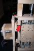
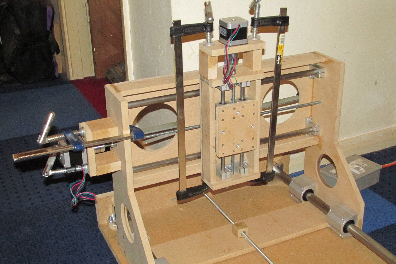
The end is just about in sight.....
Stepper motors are now fitted. Just the limit switches to fit, then wire it all up!!!.....
.... and hope it all works !!

-
Gotcha !!.. I was wondering if the USB ground needed to be connected as well.
Cheers
-
The whole thing will be powered from a 12vDC input with 5V derived from that.
The USB power option will be disconnected.
The plan there is to only connect the D+ and D- from the USB socket via a pin header on the PCB. The ground will come from the common PSU ground via J7.
-
Hi, I'm in the final planning stages of a 2-core MBLC and intend to use a GM5 mini PCB for USB connection to my PC.
reading up on the GM5 module, it says the headers at J6 can be used for direct digital connection to J11 (core).
Does this mean I can leave out the opto-couplers on both the GM5 and the core? There will be no external MIDI connections, as this is planned as a completely self-contained unit.
Many thanks in advance
-
Well.. after a busy period at work, and looking for a 'new' car, I find myself back on leave, and time to do some more work on this.
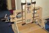
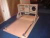
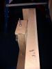
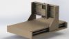
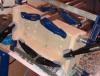
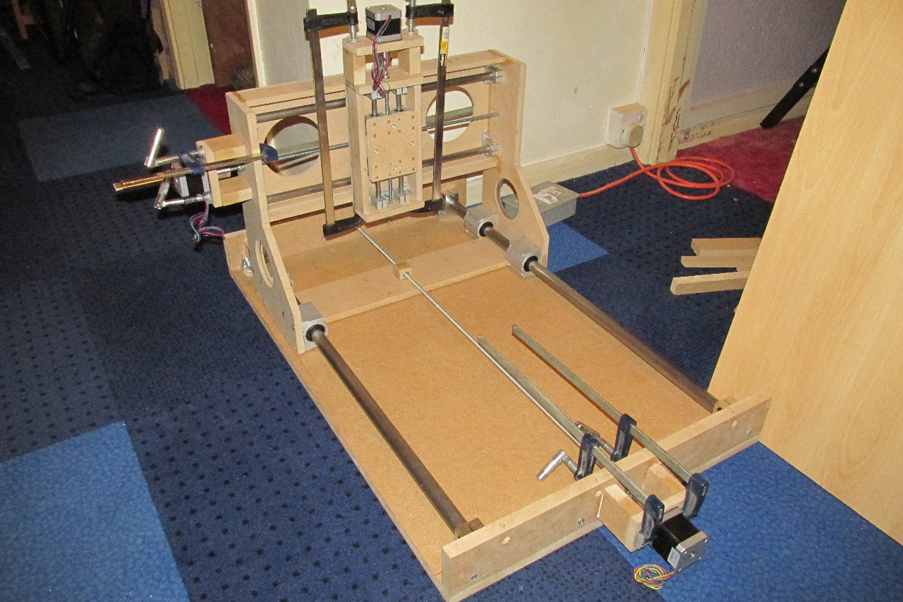
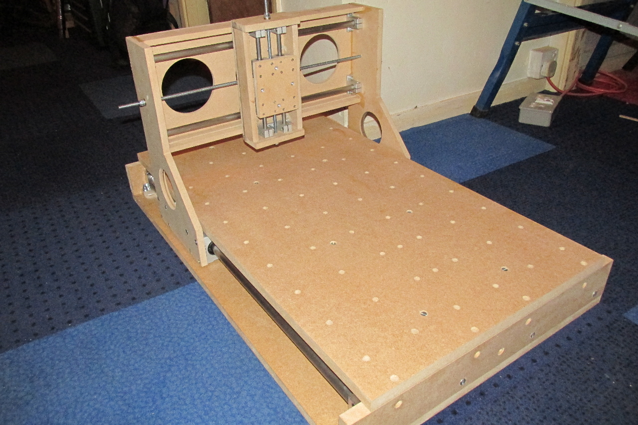
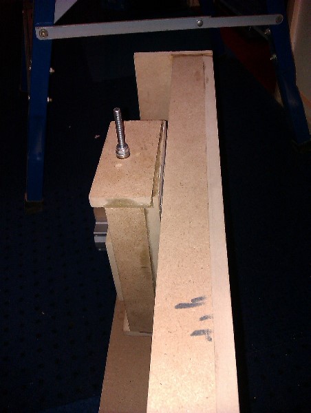
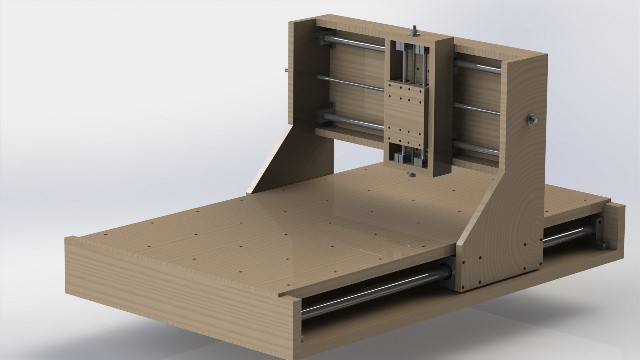
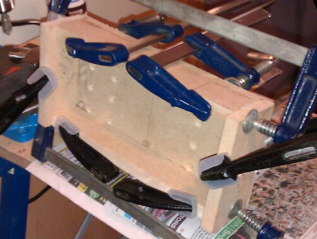
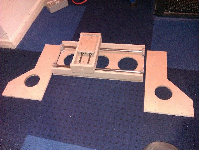
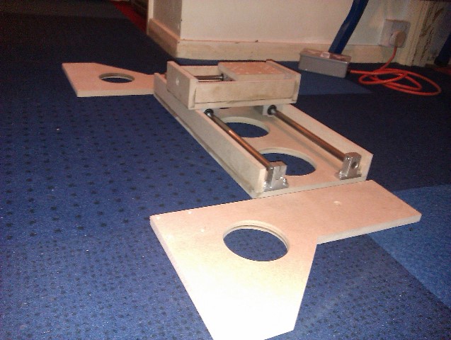
Now that I've dry fit the pieces of the base section, it's time to drill and bolt everything down.
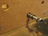
Also at this time I've drilled a grid on the table and fitted T-nuts to the underside for screw-in clamps. Note also the 2 braces on the underside of the table to reduce any flexing.
These additions to the original design, fortunately were possible without interfering with the bottom brace of the gantry
EDIT
Also showing detail of the thrust bearings used on all of the lead screws.


-
Hear, Hear... I'll second that !!!
..and third it as well !! :thumbsup:
-
I'm not sure how well it will perform with metals, though I'm hoping it will be able to cut Aluminium and Brass.
It will be the subject of some very careful experimentation. :thumbsup:
@Hawkeye - thank you, I'm hoping all the effort will be worth it.
-
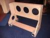
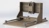
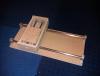
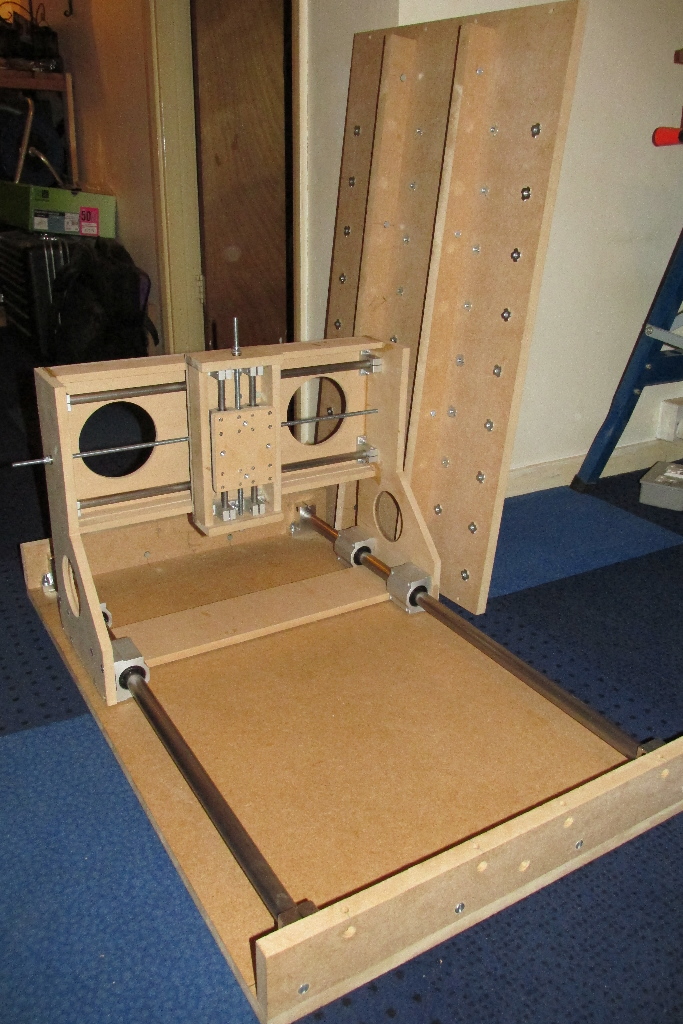
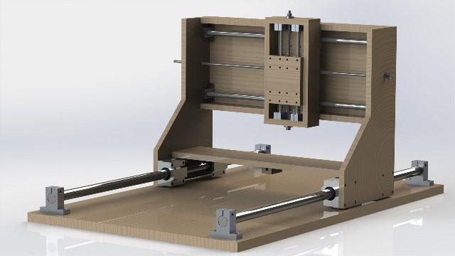
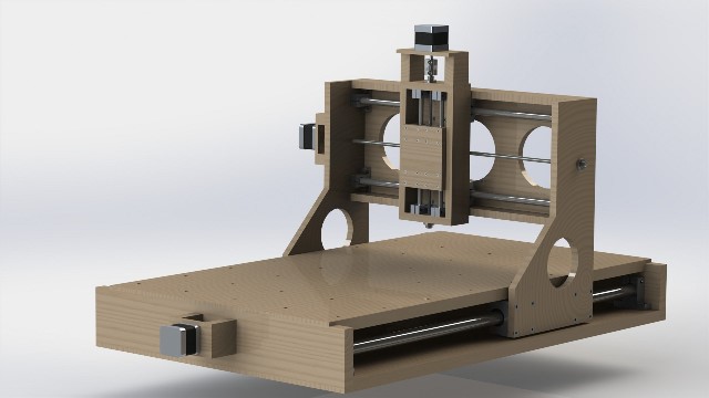
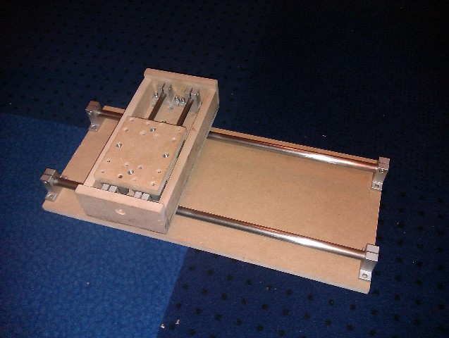
Test fitting of the gantry assembly to the baseboard, mainly to check my marking out is good before drilling.
All is as planned there, and the gantry runs smoothly on it's rails.
next was a dry fit of the rest of the base assembly, and clearances are looking good there.
time now to drill all the bolt holes , including a 9x6 grid on the table to fit 54 t-nuts, for clamping points.

-
Just arrived now,
Many thanks TK :smile:
-
excellent, thank you
-
Help!!!... Where's the list gone??... I can't remember what I ordered, now I've got a PM from TK
-
You're welcome,
Unfortunately I've never used PRO-TOOLS, so I can't really help much further, but have you tried the Logic Control XT or Mackie Control XT emulation modes?
-
If it's T-Lever fitting you want, check this out... they do all ALPS stuff, but the shipping is a bit pricey.
-
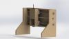
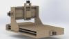
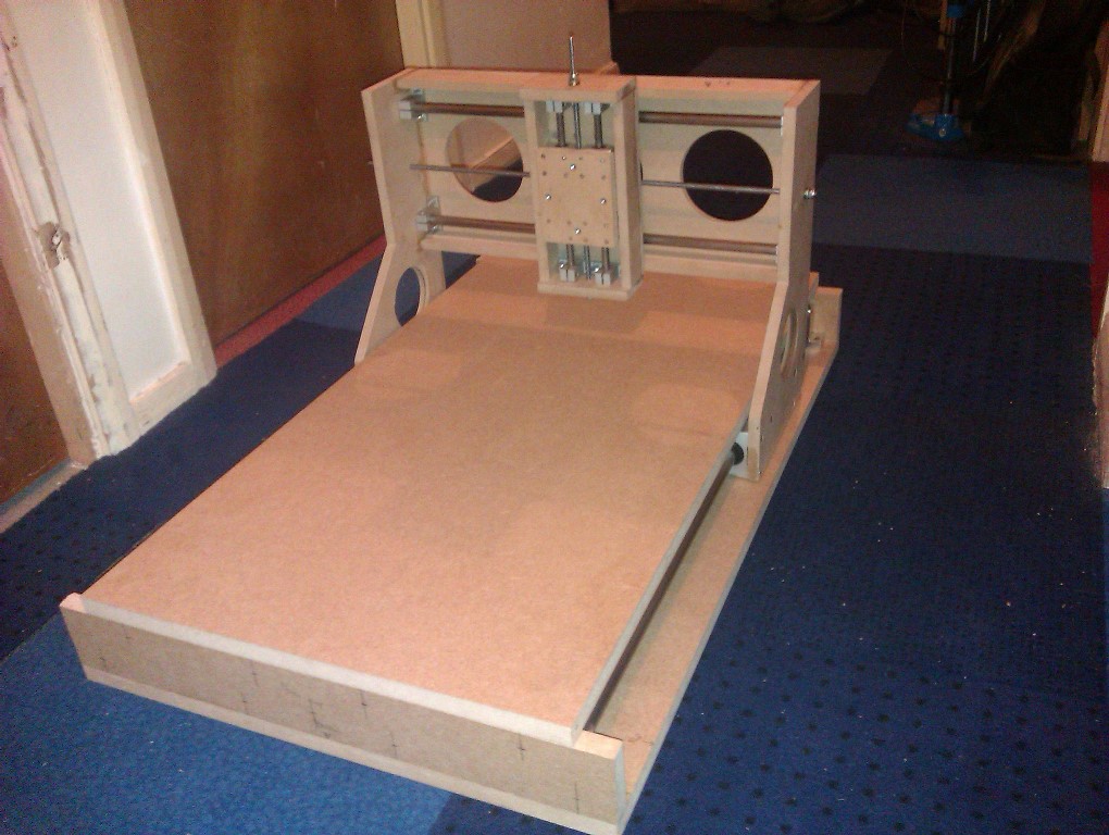
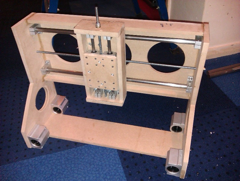
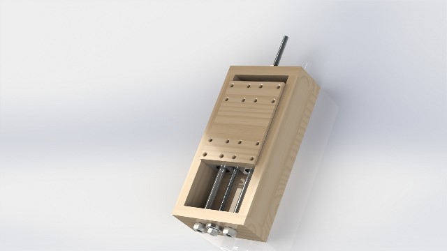
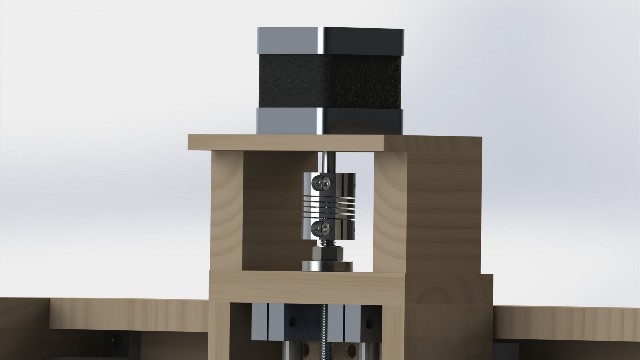
The Z-axis is now threaded up, and the slider is moving smoothly :frantics:
The gantry (X-axis) now has the bottom brace fitted and is ready to have the Z-axis mounted, and also start fitting to the base section.
Next job is the motor mounts... make all 3, and fit to the Z-axis, and then the X-axis, once the z-axis assembly is mounted and moving smoothly.


-
There's no need to upgrade the core module, the MBHP MF_NG can be connected to the PIC core.... see this thread:-
basically, the MF_NG module is placed between the GM5 and the core8 module, 1 MF_NG module per core.
-
Yes, you are right that aluminium would be more long lasting, but I've done a LOT of online research into this and most DIY CNC kits and plans use wooden frames, so it's not an un-viable option.
I don't see any reason why a wooden-framed CNC should be less accurate than an aluminium framed one. Built correctly, a wooden frame can be perfectly stiff enough to satisfy the needs of lightweight CNC work.
The other reason I decided on a wood frame was cost - as I don't have the tools to machine the sort of size pieces needed, I would have had to get them custom made, which would more than double the price tag.
-
yeah.. I was originally looking at something similar, but it's far too small for what I want, and kits for the size machine I'm building were looking at being £800-1000+
-
Thank you
It's a steady process having to cut and drill each piece accurately, and believe it or not... I've only had to re-make 1 piece!!
The advantage of a kit is that 90% of the hard work has been done, it only has to be assembled. The disadvantage is that there's limited options on what size machine you can build, I've built mine to fit the space I have.
Mine has cost me somewhere in the region of £250-300 so far, and there's still some bits to buy... e.g. drag chains to keep the cabling tidy, and channel for it to lay into. I'm expecting the total cost to be about £300.
btw, I used to live in Sheffield... went to University there.
Rob
@ rosch.. cheers, if this turns out to be accurate enough, I may be able to do the odd midiboxer a favour or 2. :wink:
-
Hi,
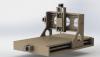
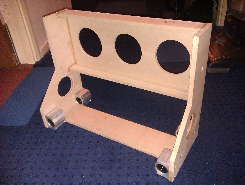
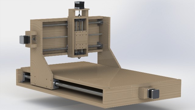
As the plans for my (upcoming) MBLC required a lot of CNC work doing, I thought to myself... Why not build one?
So... several hours of internet browsing later, and jaw-dropping of the prices of kits, I started out to design my own to the size i wanted.
The design spec was simple - to be able to rout a panel the size of a 6u rack panel.
The process of sourcing parts began, from various sources, Ebay being the most prominent, and the design started.
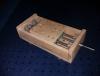
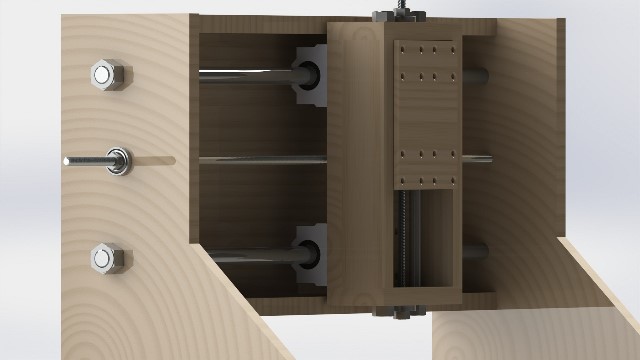
Being on a tight budget, the most expensive parts - lead screws and ballnuts were replaced with standard threaded bar and a clever arrangement of wood block and threaded inserts to reduce backlash.
Now building it starts...
Beginning with the z-axis and gantry:-


-
just found out the shift register will only output 35mA, so a transistor switch will be needed.
The only question now is... NPN or PNP ?
I had read about using a series resistance on each LED in parallel, and I'll choose these to run the LEDs at approx 15mA, which should still give a good brightness.
-
Is it possible to drive, for example, 4 LEDs from a single DOUT pin?
e.g. to make a 'light bar' indicator.
or would I need to use a transistor switch like this:-

with the 4 LEDs (and current limiting resistors) in parallel as the load. [NPN transistor assumes the DOUT pins are active high]
many thanks in advance.


Build your own tools
in Miscellaneous
Posted
The fixed wiring on the base section (X axis motor, X limit switches & E Stop switch) is now complete....
Next is the fun part... all the wiring that feeds through the drag chains.