Bääääär
-
Posts
40 -
Joined
-
Last visited
-
Days Won
1
Bääääär's Achievements
MIDIbox Newbie (1/4)
1
Reputation
-
Oh TK, you are just incredible! :frantics: :hug: Just updated the repo and adapted your demo. Pretty straight-forward. Seems like I got some typos in there, becourse my DIN is not working anymore, but that's likely a fault of mine and i hope to find the error soon. Can't believe what you do for your community here... Thanks so much!! Bääääär PS: // init SPI port MIOS32_SPI_TransferModeInit(SLAVE_SPI, MIOS32_SPI_MODE_SLAVE_CLK1_PHASE1, MIOS32_SPI_PRESCALER_128); The prescaler is not relevant here, is it?
-
Thanks, I fixed that wrong configuration. I have also tried this here in my app-background task: /* Wait for SPI1 data reception */ while (SPI_I2S_GetFlagStatus(SPI1, SPI_I2S_FLAG_RXNE) == RESET); /* Read SPI1 received data */ int x; x = SPI_I2S_ReceiveData(SPI1); // Toggle LED MIOS32_BOARD_LED_Set(1, 0); } (running in an endless loop) So if SPI1 receives something, it should turn the board led off. But it's on all the time, so I assume there's no correct transfer going on. I checked the wires, my ChipSelect is attached to RC1 which is connected to PA4 on the STM32. The datasheet says that this is the NSS Pin for SPI1. I also configured this pin as input. I don't see, why there is no sign from the SPI. It's so hard to read through the documentation and the example projects... I'm not even sure if the above code works... It's more or less a copy from one of the example projects but I didn't find where stuff like "SPI_I2S_FLAG_RXNE" is defined. The compiler gives no errors, so I hope it's defined in some header files, that have already been included by MIOS. :cry: I am currently trying to get the status register content. Ich hope to get this working tomorrow so I can post some results here. Bääääär PS: I printed the SR register with this command:/* Wait for SPI1 data reception */ while (SPI_I2S_GetFlagStatus(SPI1, SPI_I2S_FLAG_RXNE) == RESET) { MIOS32_LCD_CursorSet(0,0); MIOS32_LCD_PrintFormattedString("SR: %x", SPI1->SR); } /* Read SPI1 received data */ int x; x = SPI_I2S_ReceiveData(SPI1); // Toggle LED MIOS32_BOARD_LED_Set(1, 0);It constantly prints "SR: 2". According to the datasheet, the TXE flag is set, which is normal, becourse I did not fill the send buffer.
-
Sorry, T.K., I have to ask again... I adapted your code to fit my needs, but it doesn't. The documentation for the STM32 is very rare and the demo porjects don't help a lot at all. Maybe you can help me once again... this is my hardware.c: #define BufferSize 144 #define MIOS32_SPI0_PTR SPI1 #define MIOS32_SPI0_DMA_RX_PTR DMA1_Channel2 #define MIOS32_SPI0_DMA_TX_PTR DMA1_Channel3 #define MIOS32_SPI0_DMA_RX_IRQ_FLAGS (DMA1_FLAG_TC2 | DMA1_FLAG_TE2 | DMA1_FLAG_HT2 | DMA1_FLAG_GL2) #define MIOS32_SPI0_DMA_IRQ_CHANNEL DMA1_Channel2_IRQn #define MIOS32_SPI0_DMA_IRQHANDLER_FUNC void DMA1_Channel2_IRQHandler(void) #define MIOS32_SPI0_RCLK1_PORT GPIOA #define MIOS32_SPI0_RCLK1_PIN GPIO_Pin_4 #define MIOS32_SPI0_RCLK2_PORT GPIOC #define MIOS32_SPI0_RCLK2_PIN GPIO_Pin_15 #define MIOS32_SPI0_SCLK_PORT GPIOA #define MIOS32_SPI0_SCLK_PIN GPIO_Pin_5 #define MIOS32_SPI0_MISO_PORT GPIOA #define MIOS32_SPI0_MISO_PIN GPIO_Pin_6 #define MIOS32_SPI0_MOSI_PORT GPIOA #define MIOS32_SPI0_MOSI_PIN GPIO_Pin_7 #define SPI_SLAVE_Rx_DMA_FLAG DMA1_FLAG_TC2 uint8_t Data[BufferSize]; ///////////////////////////////////////////////////////////////////////////// //! (Re-)initializes SPI IO Pins //! By default, all output pins are configured with weak open drain drivers for 2 MHz //! \param[in] spi_pin_driver configures the driver strength: //! <UL> //! <LI>MIOS32_SPI_PIN_DRIVER_STRONG: configures outputs for up to 50 MHz //! <LI>MIOS32_SPI_PIN_DRIVER_STRONG_OD: configures outputs as open drain //! for up to 50 MHz (allows voltage shifting via pull-resistors) //! <LI>MIOS32_SPI_PIN_DRIVER_WEAK: configures outputs for up to 2 MHz (better EMC) //! <LI>MIOS32_SPI_PIN_DRIVER_WEAK_OD: configures outputs as open drain for //! up to 2 MHz (allows voltage shifting via pull-resistors) //! </UL> //! \return 0 if no error //! \return -3 if unsupported pin driver mode ///////////////////////////////////////////////////////////////////////////// s32 SPI_Slave_IO_Init(mios32_spi_pin_driver_t spi_pin_driver) { // init GPIO structure GPIO_InitTypeDef GPIO_InitStructure; GPIO_StructInit(&GPIO_InitStructure); // select pin driver and output mode u32 af_mode; u32 gp_mode; switch( spi_pin_driver ) { case MIOS32_SPI_PIN_DRIVER_STRONG: GPIO_InitStructure.GPIO_Speed = GPIO_Speed_50MHz; af_mode = GPIO_Mode_AF_PP; gp_mode = GPIO_Mode_Out_PP; break; case MIOS32_SPI_PIN_DRIVER_STRONG_OD: GPIO_InitStructure.GPIO_Speed = GPIO_Speed_50MHz; af_mode = GPIO_Mode_AF_OD; gp_mode = GPIO_Mode_Out_OD; break; case MIOS32_SPI_PIN_DRIVER_WEAK: GPIO_InitStructure.GPIO_Speed = GPIO_Speed_2MHz; af_mode = GPIO_Mode_AF_PP; gp_mode = GPIO_Mode_Out_PP; break; case MIOS32_SPI_PIN_DRIVER_WEAK_OD: GPIO_InitStructure.GPIO_Speed = GPIO_Speed_2MHz; af_mode = GPIO_Mode_AF_OD; gp_mode = GPIO_Mode_Out_OD; break; default: return -3; // unsupported pin driver mode } // MISO is output assigned to alternate functions GPIO_InitStructure.GPIO_Mode = af_mode; GPIO_InitStructure.GPIO_Pin = MIOS32_SPI0_MISO_PIN; GPIO_Init(MIOS32_SPI0_MOSI_PORT, &GPIO_InitStructure); // SCLK, MOSI, TCLK are inputs with pull-up GPIO_InitStructure.GPIO_Mode = GPIO_Mode_IN_FLOATING; GPIO_InitStructure.GPIO_Pin = MIOS32_SPI0_MOSI_PIN; GPIO_Init(MIOS32_SPI0_MISO_PORT, &GPIO_InitStructure); GPIO_InitStructure.GPIO_Pin = MIOS32_SPI0_SCLK_PIN; GPIO_Init(MIOS32_SPI0_SCLK_PORT, &GPIO_InitStructure); // RCLK outputs assigned to GPIO GPIO_InitStructure.GPIO_Mode = GPIO_Mode_IPU; GPIO_InitStructure.GPIO_Pin = MIOS32_SPI0_RCLK1_PIN; GPIO_Init(MIOS32_SPI0_RCLK1_PORT, &GPIO_InitStructure); GPIO_InitStructure.GPIO_Pin = MIOS32_SPI0_RCLK2_PIN; GPIO_Init(MIOS32_SPI0_RCLK2_PORT, &GPIO_InitStructure); return 0; // no error } ///////////////////////////////////////////////////////////////////////////// //! (Re-)initializes SPI peripheral transfer mode //! By default, all SPI peripherals are configured with //! MIOS32_SPI_MODE_CLK1_PHASE1 and MIOS32_SPI_PRESCALER_128 //! //! \param[in] spi_mode configures clock and capture phase: //! <UL> //! <LI>MIOS32_SPI_MODE_CLK0_PHASE0: Idle level of clock is 0, data captured at rising edge //! <LI>MIOS32_SPI_MODE_CLK0_PHASE1: Idle level of clock is 0, data captured at falling edge //! <LI>MIOS32_SPI_MODE_CLK1_PHASE0: Idle level of clock is 1, data captured at falling edge //! <LI>MIOS32_SPI_MODE_CLK1_PHASE1: Idle level of clock is 1, data captured at rising edge //! </UL> //! //! \return 0 if no error //! \return -4 if invalid spi_mode selected ///////////////////////////////////////////////////////////////////////////// s32 SPI_Slave_TransferModeInit( mios32_spi_mode_t spi_mode/* mios32_spi_prescaler_t spi_prescaler*/) { // SPI configuration SPI_InitTypeDef SPI_InitStructure; SPI_InitStructure.SPI_Direction = SPI_Direction_2Lines_FullDuplex; SPI_InitStructure.SPI_Mode = SPI_Mode_Slave; SPI_InitStructure.SPI_DataSize = SPI_DataSize_8b; SPI_InitStructure.SPI_FirstBit = SPI_FirstBit_MSB; switch( spi_mode ) { case MIOS32_SPI_MODE_CLK0_PHASE0: SPI_InitStructure.SPI_CPOL = SPI_CPOL_Low; SPI_InitStructure.SPI_CPHA = SPI_CPHA_1Edge; break; case MIOS32_SPI_MODE_CLK0_PHASE1: SPI_InitStructure.SPI_CPOL = SPI_CPOL_Low; SPI_InitStructure.SPI_CPHA = SPI_CPHA_2Edge; break; case MIOS32_SPI_MODE_CLK1_PHASE0: SPI_InitStructure.SPI_CPOL = SPI_CPOL_High; SPI_InitStructure.SPI_CPHA = SPI_CPHA_1Edge; break; case MIOS32_SPI_MODE_CLK1_PHASE1: SPI_InitStructure.SPI_CPOL = SPI_CPOL_High; SPI_InitStructure.SPI_CPHA = SPI_CPHA_2Edge; break; default: return -4; // invalid SPI clock/phase mode } return 0; // no error } ///////////////////////////////////////////////////////////////////////////// //! Initializes SPI0 (SPI1 in hardware) peripheral transfer mode ///////////////////////////////////////////////////////////////////////////// void SPI_Slave_Init(void) { // disable callback function //spi_callback[1] = NULL; DMA_InitTypeDef DMA_InitStructure; DMA_StructInit(&DMA_InitStructure); //NVIC_InitTypeDef NVIC_InitStructure; // IO configuration SPI_Slave_IO_Init(MIOS32_SPI_PIN_DRIVER_STRONG_OD); // enable SPI peripheral clock (APB2 == high speed) RCC_APB2PeriphClockCmd(RCC_APB2Periph_SPI1, ENABLE); // enable DMA1 clock RCC_AHBPeriphClockCmd(RCC_AHBPeriph_DMA1, ENABLE); // DMA Configuration for SPI Rx Event DMA_Cmd(MIOS32_SPI0_DMA_RX_PTR, DISABLE); DMA_InitStructure.DMA_PeripheralBaseAddr = (u32)&MIOS32_SPI0_PTR->DR; DMA_InitStructure.DMA_MemoryBaseAddr = (uint32_t)Data; DMA_InitStructure.DMA_DIR = DMA_DIR_PeripheralSRC; DMA_InitStructure.DMA_BufferSize = BufferSize; DMA_InitStructure.DMA_PeripheralInc = DMA_PeripheralInc_Disable; DMA_InitStructure.DMA_MemoryInc = DMA_MemoryInc_Enable; DMA_InitStructure.DMA_PeripheralDataSize = DMA_PeripheralDataSize_Byte; DMA_InitStructure.DMA_MemoryDataSize = DMA_MemoryDataSize_Byte; DMA_InitStructure.DMA_Mode = DMA_Mode_Normal; DMA_InitStructure.DMA_Priority = DMA_Priority_Medium; DMA_InitStructure.DMA_M2M = DMA_M2M_Disable; DMA_Init(MIOS32_SPI0_DMA_RX_PTR, &DMA_InitStructure); // initial SPI peripheral configuration SPI_Slave_TransferModeInit(MIOS32_SPI_MODE_CLK1_PHASE1); // enable SPI SPI_Cmd(MIOS32_SPI0_PTR, ENABLE); SPI_I2S_DMACmd(SPI1, SPI_I2S_DMAReq_Rx, ENABLE); } And this is my app.c: #define DEBUG_VERBOSE_LEVEL 2 ///////////////////////////////////////////////////////////////////////////// // Include files ///////////////////////////////////////////////////////////////////////////// #include <mios32.h> #include "app.h" #include <FreeRTOS.h> #include <task.h> #include <queue.h> #include "modules\UI.h" #include "modules\keys.h" #include "modules\hardware.c" #include "modules\keys.c" #include "modules\UI.c" ///////////////////////////////////////////////////////////////////////////// // This hook is called after startup to initialize the application ///////////////////////////////////////////////////////////////////////////// void APP_Init(void) { MIOS32_DELAY_Init(0); // Init a timer for the UI MIOS32_TIMER_Init(1, 40000, UI, MIOS32_IRQ_PRIO_LOW); // initialize MIOS32 Timer #0, so that our "key-value readout" function is // called each 1,2 ms: //MIOS32_TIMER_Init(0, 2000, Timer, MIOS32_IRQ_PRIO_HIGH); Keys_Init(); // not relevant yet SPI_Slave_Init(); UI_Init(); // my UI, not relevant too // initialize all LEDs MIOS32_BOARD_LED_Init(0xffffffff); } ///////////////////////////////////////////////////////////////////////////// // This task is running endless in background ///////////////////////////////////////////////////////////////////////////// void APP_Background(void) { while(1) { /* Wait for DMA1 transfer complete */ while (!DMA_GetFlagStatus(SPI_SLAVE_Rx_DMA_FLAG)); // Toggle LED MIOS32_BOARD_LED_Set(1, ~MIOS32_BOARD_LED_Get()); int i; // Bring data in right order for (i=0; i<12; i=i+2) { Values[8*i ] = (Data[i*3/2 + 1]<<4) | ((Data[i*3/2 + 2]&0b11110000)>>4); Values[8*i + 1] = (Data[i*3/2 + 19]<<4) | ((Data[i*3/2 + 20]&0b11110000)>>4); Values[8*i + 2] = (Data[i*3/2 + 37]<<4) | ((Data[i*3/2 + 38]&0b11110000)>>4); Values[8*i + 3] = (Data[i*3/2 + 55]<<4) | ((Data[i*3/2 + 56]&0b11110000)>>4); Values[8*i + 4] = (Data[i*3/2 + 73]<<4) | ((Data[i*3/2 + 74]&0b11110000)>>4); Values[8*i + 5] = (Data[i*3/2 + 91]<<4) | ((Data[i*3/2 + 92]&0b11110000)>>4); Values[8*i + 6] = (Data[i*3/2 + 109]<<4) | ((Data[i*3/2 + 110]&0b11110000)>>4); Values[8*i + 7] = (Data[i*3/2 + 127]<<4) | ((Data[i*3/2 + 128]&0b11110000)>>4); Values[8*(i+1) ] = (Data[i*3/2 + 2]<<8) | Data[i*3/2 + 3]; Values[8*(i+1) + 1] = (Data[i*3/2 + 20]<<8) | Data[i*3/2 + 21]; Values[8*(i+1) + 2] = (Data[i*3/2 + 38]<<8) | Data[i*3/2 + 39]; Values[8*(i+1) + 3] = (Data[i*3/2 + 56]<<8) | Data[i*3/2 + 57]; Values[8*(i+1) + 4] = (Data[i*3/2 + 74]<<8) | Data[i*3/2 + 75]; Values[8*(i+1) + 5] = (Data[i*3/2 + 92]<<8) | Data[i*3/2 + 93]; Values[8*(i+1) + 6] = (Data[i*3/2 + 110]<<8) | Data[i*3/2 + 111]; Values[8*(i+1) + 7] = (Data[i*3/2 + 128]<<8) | Data[i*3/2 + 129]; } } } [...] Any Idea? Bääääär
-
Without having checked that, lot's of interrupt sources are OR'ed together to trigger a common interrupt. Might be the same for the two DMA channels. Not sure about that, though. Ok, I found this here in the datasheet: Depends on what interrupts you use. Hopefully not 4+5?! (what line does the STM32F103... belong to btw? Ouch, didn't read it carefull enough I guess. Thanks, that solved it. Yeha, I can work on :frantics: Bääääär
-
Hi there, I just found some time to read through several million pages of STM32 docu and DMA/SPI Example applications and put together my version of SPI0 in slave mode. I decided to use DMA, it just seemed like a good idea to me. In App-Background task I wait until the DMA sets it's flag. (I'M using no interrupts here to make it a bit easier first) Now, what I did: I declared a DONT_USE_SPI0 so MIOS32 does not attempt to configure this peripheral. Then I copied some of your code from the spi.c file into a blank file and modified it. I saved it as hardware.c and included it in my app.c. However, the compiler spits out lots of errors about missing definitions such as modules\hardware.c:64: error: 'MIOS32_SPI0_MISO_PIN' undeclared (first use in this function) These definitions must have been declared somewhere else before. All those MIOS32 functions use them too, so they must be well-known for the compiler, when it starts to compile my stuff. I tried hard to find why there are these errors, but I have no clue. See my app.c file:#include <mios32.h> #include "app.h" #include <FreeRTOS.h> #include <task.h> #include <queue.h> #include "modules\UI.h" #include "modules\keys.h" #include "modules\hardware.c" // <== This is the file, where i put my initialisations in #include "modules\keys.c" #include "modules\UI.c" I can post my hardware.c file, too if neccessary. Trying to understand that... DMA_IT_TC - didn't find that somewhere. The datasheet notes some TC_IE and TC_IF flags. I guess you mean TC_IE here (it controls the generation of an interrupt). Becourse setting the TC_IF flag is pointless. This flag is already set by hardware long before the RX channel is finished (in concrete: it is set, when the DMA transfering from RAM to SPI has finished it's work) Correct me if I got something wrong here (which is likely :rolleyes: ) Thanks for your great support! Bääääär
-
Haha, this forum is almost a chat ;) I'm not 100% sure but I remember that the transmit buffer is cleared by hardware after each byte. I didn't find something about this in the datasheet. If not, then it could work. Otherwise it's pointless. But I will try to find information about this, because it's generally a nice (but dirty) idea. Regarding the callback-too-early problem: I found this in a german forum. Seems to be the problem. At least it's exactly what happens here. I think, I will go with the slave solution. Can't be wrong to learn a bit more about this processor. Thanks for your help, you're great! I guess this problem can be marked as "solved". Bääääär
-
Ahh, would be great, but thats too fast for the AVR. The datasheet says: Anyways, it's a good idea to reduce data. Unfortunatly I have only a very small AVR on this board, it has just 4kB of flash anyway. So it won't be possible. I posted a question regarding this on the http://www.mikrocontroller.net forums and a guy answered: It should be possible to make the STM32 slave and the AVR master of the transmission. That's actually a great way to do it, don't know why I didn't notice before. It's always guaranteed, that the readout happens in exactly the same intervals, no matter what the STM32 does at this time. Great! I read through the mios32-spi files for the STM32 and it seems like it should be possible to init the DMA for SPI slave operation. I'll try to get this working, it's just too promising. Bääääär PS: I don't understand... the isr would be triggered after the dummy bytes and after the real bytes. Effectivly I would miss both. What's the trick here?
-
Ok, i found the reason for the strange prescaler behaviour: I have to configure it before I configure the timer. Any idea why? So, when I use The 64 prescaler and a time of 1200us it looks very promising. But, when you look closer, there's still a lot of strange things going on. Ok, first the overall timing: My timer priority is MIOS32_IRQ_PRIO_LOW, thst's why there is this large gap on the right side I suppose? Besides that, it looks good, fits well into the timeframe of 1200us and the transmission starts after the second block of values has been read from the chips (you can separate the blocks by those tiny little spikes on the ADC_CS channel). But when you look closer: I adviced the slave to send always 0b11011011 (btw that makes the ISR for buffer-refilling 1 tick faster). But what do we see? Somehow delayed sometimes. Looks like the AVR ist still to slow... And there is something related to MIOS32: At the end, you see that the callback is entered, before (!) the last byte is finished. What's going on there? Bääääär PS: I tried it with prescaler 128 and 4ms timer-cycle. This low speed gives enough time for buffer refilling and the transmission is without errors. Seems like my ISR does need some cycles more in reality than in the simulator. What does it mean? I can't use DMA this way. I need to find a way to introduce gaps between two bytes of a transmission. at least 1us. sh*t
-
What about making one byte 9 bits long? Well not exactly of course :D , but I could use the DMA at prescaler_16 just like before and just read some more bytes. Effectivly my slave would miss one clock-edge every time it reloads its buffers. So if the transmission at prescaler_16 should be 0b11111111 0b11111111 0b11111111 ... it would become something like 0b11111111 0b01111111 0b10111111 0b11011111 (where 0 is the bit that the slave skipped due to reloading its buffers). I would need to transmit some more bytes, but it could work. However I would need to reassemble the received data in a very strange and mind-twisting way. :wacko:
-
Could be a solution, but there is one problem: After pulling Enable low, the slave immediately starts reading values. It needs 87,9us to get the first set of values. I already programmed this in assembler, so I can't make it much faster. I therefore have to wait at least 87,9us before I can start reading values. But let me claculate a bit... The actual transmission takes 1023us, adding another ~90us we get 1113us, this taken as refresh-rate gives 898 Hz. I could try this. Too sad that I loose lots of precision here. 1ms refresh rate was already a hard step, best would have been 0,8ms. (Background: pressing a key on the keyboard takes at least 1ms when pressing really hard. The faster i can read this, the better. Imagine, you press the key 0,5ms after the last readout, then I would get one value (0,5ms later) with the key half depressed and the next 1,5ms later fully depressed. The caluclated velocity would be less than it should actually be.) Ok, tried it, but there is some strange behaviour... Prescaler settings of 32 or 64 both result in a clock rate of 3,5us. That should be prescaler_256. I did "make clean" and all that stuff. Whats wrong there? This is my code: void ReadOutCallback(void) { MIOS32_SPI_RC_PinSet(0,0,1); int i; // Bring data in right order for (i=0; i<12; i=i+2) { Values[8*i ] = (Data[i*3/2 + 1]<<4) | ((Data[i*3/2 + 2]&0b11110000)>>4); Values[8*i + 1] = (Data[i*3/2 + 19]<<4) | ((Data[i*3/2 + 20]&0b11110000)>>4); Values[8*i + 2] = (Data[i*3/2 + 37]<<4) | ((Data[i*3/2 + 38]&0b11110000)>>4); Values[8*i + 3] = (Data[i*3/2 + 55]<<4) | ((Data[i*3/2 + 56]&0b11110000)>>4); Values[8*i + 4] = (Data[i*3/2 + 73]<<4) | ((Data[i*3/2 + 74]&0b11110000)>>4); Values[8*i + 5] = (Data[i*3/2 + 91]<<4) | ((Data[i*3/2 + 92]&0b11110000)>>4); Values[8*i + 6] = (Data[i*3/2 + 109]<<4) | ((Data[i*3/2 + 110]&0b11110000)>>4); Values[8*i + 7] = (Data[i*3/2 + 127]<<4) | ((Data[i*3/2 + 128]&0b11110000)>>4); Values[8*(i+1) ] = (Data[i*3/2 + 2]<<8) | Data[i*3/2 + 3]; Values[8*(i+1) + 1] = (Data[i*3/2 + 20]<<8) | Data[i*3/2 + 21]; Values[8*(i+1) + 2] = (Data[i*3/2 + 38]<<8) | Data[i*3/2 + 39]; Values[8*(i+1) + 3] = (Data[i*3/2 + 56]<<8) | Data[i*3/2 + 57]; Values[8*(i+1) + 4] = (Data[i*3/2 + 74]<<8) | Data[i*3/2 + 75]; Values[8*(i+1) + 5] = (Data[i*3/2 + 92]<<8) | Data[i*3/2 + 93]; Values[8*(i+1) + 6] = (Data[i*3/2 + 110]<<8) | Data[i*3/2 + 111]; Values[8*(i+1) + 7] = (Data[i*3/2 + 128]<<8) | Data[i*3/2 + 129]; } MIOS32_SPI_RC_PinSet(0,0,0); } void Timer (void) { MIOS32_SPI_TransferBlock(0, NULL , Data, 144, ReadOutCallback); } ///////////////////////////////////////////////////////////////////////////// // This hook is called after startup to initialize the application ///////////////////////////////////////////////////////////////////////////// void APP_Init(void) { MIOS32_DELAY_Init(0); // Init a timer for the UI MIOS32_TIMER_Init(1, 40000, UI, MIOS32_IRQ_PRIO_LOW); // initialize MIOS32 Timer #0, so that our "key-value readout" function is // called each 1,2 ms: // This should do the same thing like changing the rtos tick length, I guess MIOS32_TIMER_Init(0, 1200, Timer, MIOS32_IRQ_PRIO_LOW); MIOS32_SPI_TransferModeInit(0, MIOS32_SPI_MODE_CLK1_PHASE1, MIOS32_SPI_PRESCALER_64); Keys_Init(); UI_Init(); // initialize all LEDs MIOS32_BOARD_LED_Init(0xffffffff); } Thanks a lot Bääääär
-
I know. But, as I wrote in my first post: The main problem is, that the AVR on the slave board is too slow to refill it's sending buffers in between the transmission of two bytes. I need very small gaps between two bytes (only about 450ns). I first tried to achieve these gaps by only configuring the DMA to transmit 1 byte, then in the callback to transmit the next byte until all bytes are transmitted. The overhead of reconfiguring the DMA after every byte was just ways too much, so the gaps got too big and the Read-Out function got too long so it blocked USB and other stuff. The second attempt was my last post, but this it just too much cpu- consuming. If I use the DMA, as you suggested, then there are no gaps and my slave can't fill its buffers until the STM32 toggles the CLK-line the next time. If I use DMA and use a higher prescaler, there would be enough time to refill the sending buffers for the slave, but the overall time for one transmission would be too long to fit into the timeframe of 1ms. Edit: I just checked that: the time between two rising edges of CLK is 230ns, this is the time, that I have to reload the buffers at the slave side. According to the simulation in AVR Studio, the interrupt service routine to do this takes at least 0.45us. This is the fastest ISR I can program on this 20MHz CPU. It just enters the ISR (5 cycles), loads data into the register (two cycles), pops them out to the SPI Hardware (overall 9 cycles @20MHz). I searched the web, if it's possible to make the DMA insert little gaps between two bytes, but thas seems not to be possible. Bääääär PS: BTW: Thanks for your support, T.K.. It's really applaudable, that you find time to make all those Midibox developments and still answer so many support questions!
-
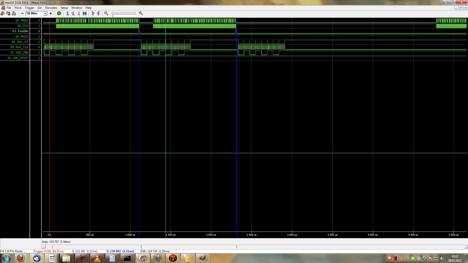
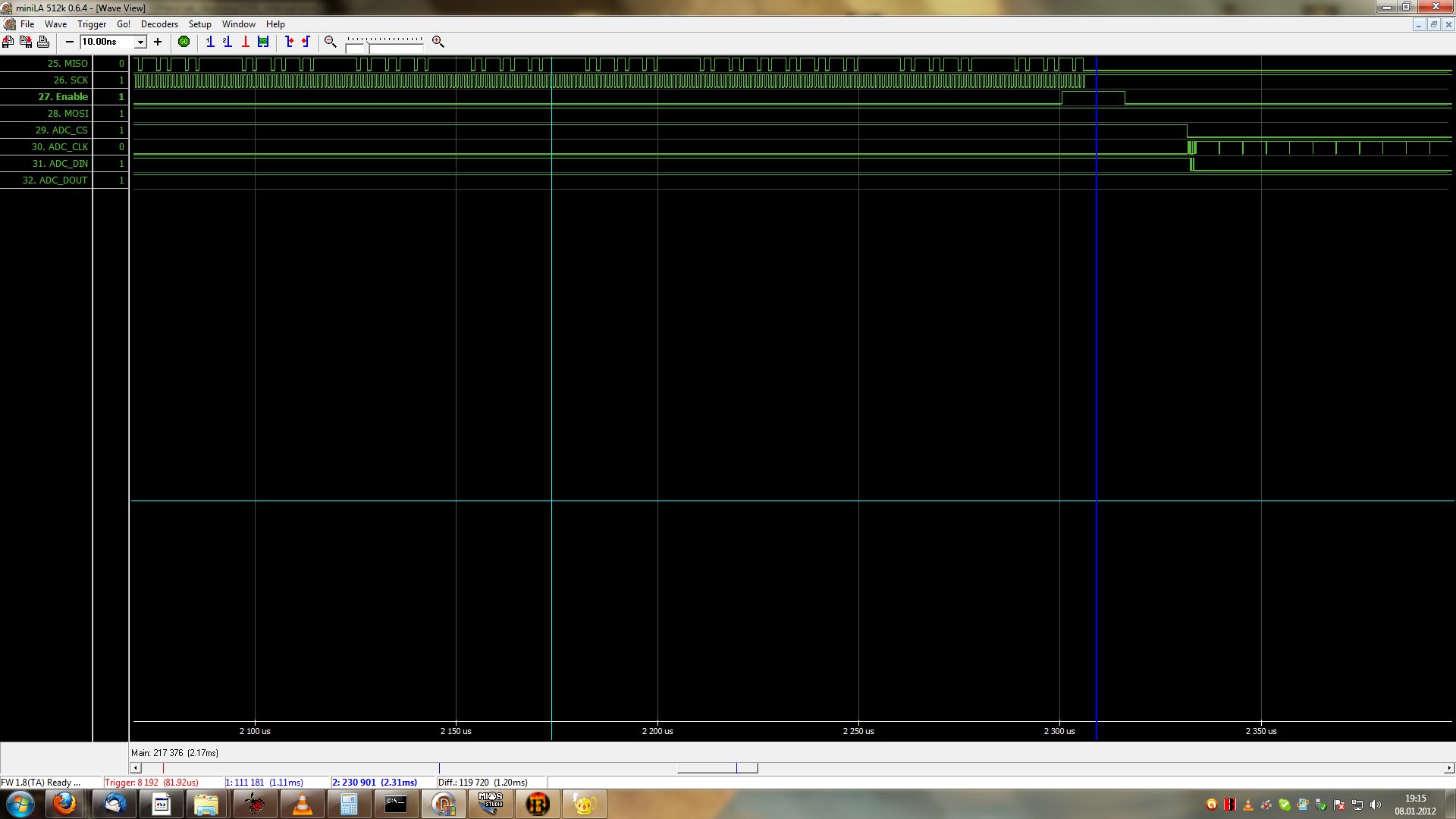
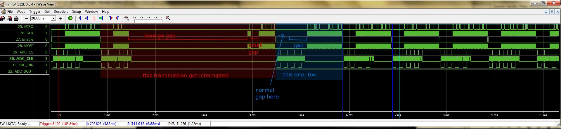
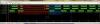
Hi T.K.! I have a logic analyser now and some time to go on with development. Using this new great tool, I noticed, that the delays in between two bytes are pretty large with the method of my last post. I tried the version, you advised (low priority task to read values from my slave board). Works pretty fine now after some troubleshooting... Attached is a screenshot of some transmissions. The marked area between the two blue cursors/lines is one transmission. The upper four channels show the transmission between STM32 and my slave board. The lower four lines show whats going on at the slave side (these are the lines between my slave uC and the ADC chips). You can see, after the STM32 pulls Enable low, the slave starts reading values from the ADCs. Halfways the STM32 starts reading values. But take a look at the left side of the picture: There is a laaaarge gap and a small gap from 1ms to 4,5ms interrupting the transfer marked in red. And from 4,5ms to ~5,8ms there is another gap interrupting another transfer marked in blue. Both effectivly make the time between two transmissions very irregular. This inacceptable for me, how could I calculate corrrect velocity values from this? Here is my code for this: [...] ///////////////////////////////////////////////////////////////////////////// // Local definitions ///////////////////////////////////////////////////////////////////////////// #define PRIORITY_TASK_READOUT ( tskIDLE_PRIORITY + 2 ) ///////////////////////////////////////////////////////////////////////////// // Prototypes ///////////////////////////////////////////////////////////////////////////// static void TASK_ReadOut(void *pvParameters); //////////////////////////////////////////////////////////////////////// // readout task //////////////////////////////////////////////////////////////////////// // This task reads data from the slave board every 1ms. // Data arrives as 144 bytes. Three bytes actually contain only two 12bit // values. At the end, this function melts 1,5 bytes to one 12bit value. // Because the values are also in the wrong order, it also sorts them // so they are in the right oder. It would have been better to // let the slave CPU do this - however the 20MHz 8bit ATMega used as // the slave is already busy reading the values from the ADC chips and // transmitting them to the master. static void TASK_ReadOut(void *pvParameters) { while(1) { // wait for next timesplice (1 mS) vTaskDelay(1 / portTICK_RATE_MS); counter = 0; int i; for (i=0; i<144; i++) { Data[counter] = MIOS32_SPI_TransferByte(0, 0b10010110); counter++; MIOS32_DELAY_Wait_uS(1); } MIOS32_SPI_RC_PinSet(0,0,1); // Bring data in right order for (i=0; i<12; i=i+2) { Values[8*i ] = (Data[i*3/2 + 1]<<4) | ((Data[i*3/2 + 2]&0b11110000)>>4); Values[8*i + 1] = (Data[i*3/2 + 19]<<4) | ((Data[i*3/2 + 20]&0b11110000)>>4); Values[8*i + 2] = (Data[i*3/2 + 37]<<4) | ((Data[i*3/2 + 38]&0b11110000)>>4); Values[8*i + 3] = (Data[i*3/2 + 55]<<4) | ((Data[i*3/2 + 56]&0b11110000)>>4); Values[8*i + 4] = (Data[i*3/2 + 73]<<4) | ((Data[i*3/2 + 74]&0b11110000)>>4); Values[8*i + 5] = (Data[i*3/2 + 91]<<4) | ((Data[i*3/2 + 92]&0b11110000)>>4); Values[8*i + 6] = (Data[i*3/2 + 109]<<4) | ((Data[i*3/2 + 110]&0b11110000)>>4); Values[8*i + 7] = (Data[i*3/2 + 127]<<4) | ((Data[i*3/2 + 128]&0b11110000)>>4); Values[8*(i+1) ] = (Data[i*3/2 + 2]<<8) | Data[i*3/2 + 3]; Values[8*(i+1) + 1] = (Data[i*3/2 + 20]<<8) | Data[i*3/2 + 21]; Values[8*(i+1) + 2] = (Data[i*3/2 + 38]<<8) | Data[i*3/2 + 39]; Values[8*(i+1) + 3] = (Data[i*3/2 + 56]<<8) | Data[i*3/2 + 57]; Values[8*(i+1) + 4] = (Data[i*3/2 + 74]<<8) | Data[i*3/2 + 75]; Values[8*(i+1) + 5] = (Data[i*3/2 + 92]<<8) | Data[i*3/2 + 93]; Values[8*(i+1) + 6] = (Data[i*3/2 + 110]<<8) | Data[i*3/2 + 111]; Values[8*(i+1) + 7] = (Data[i*3/2 + 128]<<8) | Data[i*3/2 + 129]; } MIOS32_SPI_RC_PinSet(0,0,0); } } ///////////////////////////////////////////////////////////////////////////// // This hook is called after startup to initialize the application ///////////////////////////////////////////////////////////////////////////// void APP_Init(void) { MIOS32_DELAY_Init(0); // Init a timer for the UI MIOS32_TIMER_Init(1, 40000, UI, MIOS32_IRQ_PRIO_LOW); MIOS32_SPI_TransferModeInit(0, MIOS32_SPI_MODE_CLK1_PHASE1, MIOS32_SPI_PRESCALER_16); // start matrix scan task xTaskCreate(TASK_ReadOut, (signed portCHAR *)"ReadOut", configMINIMAL_STACK_SIZE, NULL, PRIORITY_TASK_READOUT , NULL); Keys_Init(); UI_Init(); // initialize all LEDs MIOS32_BOARD_LED_Init(0xffffffff); } [...] To get rid of these gaps i have to increase the priority of the task. But if I increase the priority, I have those hangs again... The only chance to get around this is to force the DMA to introduce small gaps between two bytes. This way, i would not need such a cpu-consuming routine to read out values from the slave board. I could use a high-priority task to start the DMA and a low priority task to do the velocity calculation. Is this possible? Johannes
-
Hi there! I'm having trouble using the timers of my STM32-Core, because it keeps hanging and freezing, once I initialise them. Let me show you some code: ///////////////////////////////////////////////////////////////////////////// // This hook is called after startup to initialize the application ///////////////////////////////////////////////////////////////////////////// void APP_Init(void) { MIOS32_DELAY_Init(0); // initialize MIOS32 Timer #0, so that our "key-value readout" function is // called each 1 ms: MIOS32_TIMER_Init(0, 1000, Timer, MIOS32_IRQ_PRIO_LOW); // Init a timer for the UI MIOS32_TIMER_Init(1, 40000, UI, MIOS32_IRQ_PRIO_LOW); MIOS32_SPI_TransferModeInit(0, MIOS32_SPI_MODE_CLK1_PHASE1, MIOS32_SPI_PRESCALER_16); Keys_Init(); // only initialising variables UI_Init(); // same here // initialize all LEDs MIOS32_BOARD_LED_Init(0xffffffff); } My UI timer works fine, so there's no problem. The strang thing is my other timer: //////////////////////////////////////////////////////////////////////// // callback function of the readout timer. //////////////////////////////////////////////////////////////////////// // Data arrives as 144 bytes. Three bytes actually contain only two 12bit // values. At the end, this function melts 1,5 bytes to one 12bit value. // Because the values are also in the wrong order, it also sorts them // so they are in the right oder. It would have been better to // let the slave CPU do this - however the 20MHz 8bit ATMega used as // the slave is already busy reading the values from the ADC chips and // transmitting them to the master. void callback (void) { Data[counter] = byte[0]; if (counter >= 144) { MIOS32_SPI_RC_PinSet(0,0,1); int i; // Bring data in right order for (i=0; i<12; i=i+2) { Values[8*i ] = (Data[i*3/2 + 1]<<4) | ((Data[i*3/2 + 2]&0b11110000)>>4); Values[8*i + 1] = (Data[i*3/2 + 19]<<4) | ((Data[i*3/2 + 20]&0b11110000)>>4); Values[8*i + 2] = (Data[i*3/2 + 37]<<4) | ((Data[i*3/2 + 38]&0b11110000)>>4); Values[8*i + 3] = (Data[i*3/2 + 55]<<4) | ((Data[i*3/2 + 56]&0b11110000)>>4); Values[8*i + 4] = (Data[i*3/2 + 73]<<4) | ((Data[i*3/2 + 74]&0b11110000)>>4); Values[8*i + 5] = (Data[i*3/2 + 91]<<4) | ((Data[i*3/2 + 92]&0b11110000)>>4); Values[8*i + 6] = (Data[i*3/2 + 109]<<4) | ((Data[i*3/2 + 110]&0b11110000)>>4); Values[8*i + 7] = (Data[i*3/2 + 127]<<4) | ((Data[i*3/2 + 128]&0b11110000)>>4); Values[8*(i+1) ] = (Data[i*3/2 + 2]<<8) | Data[i*3/2 + 3]; Values[8*(i+1) + 1] = (Data[i*3/2 + 20]<<8) | Data[i*3/2 + 21]; Values[8*(i+1) + 2] = (Data[i*3/2 + 38]<<8) | Data[i*3/2 + 39]; Values[8*(i+1) + 3] = (Data[i*3/2 + 56]<<8) | Data[i*3/2 + 57]; Values[8*(i+1) + 4] = (Data[i*3/2 + 74]<<8) | Data[i*3/2 + 75]; Values[8*(i+1) + 5] = (Data[i*3/2 + 92]<<8) | Data[i*3/2 + 93]; Values[8*(i+1) + 6] = (Data[i*3/2 + 110]<<8) | Data[i*3/2 + 111]; Values[8*(i+1) + 7] = (Data[i*3/2 + 128]<<8) | Data[i*3/2 + 129]; } MIOS32_SPI_RC_PinSet(0,0,0); } else { counter++; MIOS32_SPI_TransferBlock(0, NULL, byte, 1, &callback); } } //////////////////////////////////////////////////////////////////////// // Readout Timer //////////////////////////////////////////////////////////////////////// // This Timer is called every ms to start reading values from the slave. // It only reads one byte an then calls a callback function to read the // next byte until all bytes are read. // This behaviour introduces small gaps in between the single bytes and // give the slow 20MHz slave CPU some time to refill its sending buffers. void Timer(void) { counter = 0; MIOS32_SPI_TransferBlock(0, NULL, byte, 1, &callback); } What am I trying to do? I'm trying to midify a real piano. For this purpose i have installed an optical sensor under each key. The sensor detects, how deep the key is depressed. I need to scan these every 1ms to get a result, that allows me to calculate a good velocity value. So there are 96 optical sensors, that need to be scanned with at least 1000Hz. I have built me a slave board with an AVR@20MHz to scan 12 8-channel-ADCs and send over the results to the STM32-Core. For the results are 12bit, I need to send them over als 144bytes, where 3 bytes actually contain only two values bit-wise. The slave board is working fine. However, the time frame is very limited. The main problem is, that the AVR is too slow to refill it's sending buffers in between the transmission of two bytes. So i use the above version to introduce small gaps in between two bytes. This is done by the overhead of recalling the DMA after each byte. I don't know, if it's a good solution, but it seemed to work for 40ms delays. However I need 1ms (or even less). So what happens, when I upload this code to the STM32? It freezes. I'd like to know why, because my timer function should be an easy task for this CPU (as it has hardware multiplier and division units). All I do is configuring the DMA 144 times (ok, that's sick, I know) and doing some math at the end. Even if the time between the DMA call and the callback function is very long - there should be some time to serve USB and my UI task, too. So here I am and I have no idea what to do... Maybe you have an idea for me, Thank you! Bääääär PS: I have not been successfull using the RTOS-cpu-measurements. I followed the guide on the doxygen page, but can't compile due to missing functions (?).
-
how to arrange LED's in a circle with eagle
Bääääär replied to sidmonster's topic in Design Concepts
There's an ulp for that. Take a look at cmd-draw.ulp It does exactly what you need (and even more). Experiment with its settings, its pretty straight forward. Just put some LEDs on your board, with names adjunct to each other. Example LED10, LED11, LED12, LED13. The run the ulp and select "Move". (You want the LEDs to be moved). Enter the name of the first element, then radius, start and stop angle (and don't forget to set a tick on "rotate item to match") and what else you might want to let the script do. Then hit enter and be happy :) Bääääär -
Slow SPI on J19 and multitasking
Bääääär replied to Bääääär's topic in MIOS programming (C)
I just found out that the prescaler for HW SPI can't be set low enough for 40kHz SPI. I'll have to go the SW way then...