
norbim1
-
Posts
77 -
Joined
-
Last visited
-
Days Won
2
Content Type
Profiles
Forums
Blogs
Gallery
Posts posted by norbim1
-
-
Hi Mike,
Attached the schema of my DAC modification.
I'll take some photos also, and try to post tomorrow.
Norbim
-
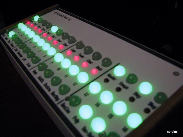
I'm just finishing a box with the XG60 (NEC clone) based on the MistralXG project (with PIC18F2550, USB). My mods:
- The audio output from the card is quite noisy, so I bypass the original DAC on the XG board. I connected the PCM data lines to a small board with PCM1754 DAC with very good result.
- Audio input with opamp buffers to the XG60
- Modified Midi routing circuit
- SW mod for the PIC (routing, flash for patches, mode selection, instrument selection etc.)
Current state:
HW is almost ready and working. SW is under dev.
-
Hi, I'm in for 8.
-
Hi Torsten,
I found the solution, but it's a litle bit strange: I changed the IC2 from HCT595 to HC595. Even that the schematic suggest HCT595 for 5V LCD-s, my LCDs didn't work with it, but both work perfect with the HC595. I don't know wether others have same experience?
Best regards, Norbert
-
Thanks a lot Thorsten,
You are right, it doesn't make sense, where the RW set to zero is. I double checked all the connections, also the 5V jumper is OK. I have a 4*20 LCD on my MIOS8, which is working OK, sothe next step will be creating a cross connect cable, I'll try this LCD width my MIOS8 core and the 4*20 width the LPC core. I hope it will show where the problem is.
I'll report the result here.
Best regards, Norbert
-
Hi Torsten,
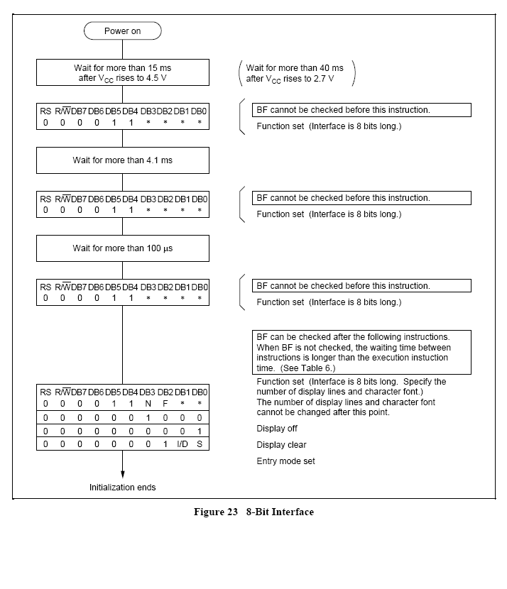
Thanks for the fast response, first of all, let me say a big thanks for this amazing project. I totally agree with the timing issue, but I'm thinking about the initialization process of the LCD. According the data sheet:

It states, that in the first 3 init instruction the RW line should be at zero, but in the code, the RW line set to zero after the first instruction (after the E line pulse). I checked the MIOS8 LCD code, and there the sequence is according the data sheet. So I suggest the following code for the first init command:
// initialize LCD
MIOS32_BOARD_J15_DataSet(0x38);
MIOS32_BOARD_J15_RS_Set(0);
MIOS32_BOARD_J15_RW_Set(0);
MIOS32_BOARD_J15_E_Set(mios32_lcd_device, 1);
MIOS32_BOARD_J15_E_Set(mios32_lcd_device, 0);
MIOS32_DELAY_Wait_uS(50000);
BR, Norbert
-
Hi all,
I tried to use a 2*20 LCD (type JHD202C with standard HD44780 like chip) with LPC core, but it was unsuccesful. After I checked all the connections and soldering, I compared the universal LCD driver with the datasheet. I found in the LCD init part of the universal LCD driver code :
// initialize LCD
MIOS32_BOARD_J15_DataSet(0x38);
MIOS32_BOARD_J15_RS_Set(0);
MIOS32_BOARD_J15_E_Set(mios32_lcd_device, 1);
MIOS32_BOARD_J15_E_Set(mios32_lcd_device, 0);
MIOS32_BOARD_J15_RW_Set(0);
MIOS32_DELAY_Wait_uS(50000);
In the first init command the RW set to zero after the E line trigger, but I think it should be before. As I haven't install the toolchain jet. could anybody please check that my founding was correct or not?
Thanks a lot for Your kind help
Put Waveblaster daughter board (Yamaha DB50XG) in a box?
in Design Concepts
Posted
I have my glasses, my head magnifier :) With some practice it's not so hard work.
Here are the promised pics.