

ArnoNym
-
Posts
31 -
Joined
-
Last visited
-
Days Won
2
Content Type
Profiles
Forums
Blogs
Gallery
Posts posted by ArnoNym
-
-
Is the group buy from blingy still open?
I am interested in one pair.
-
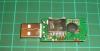
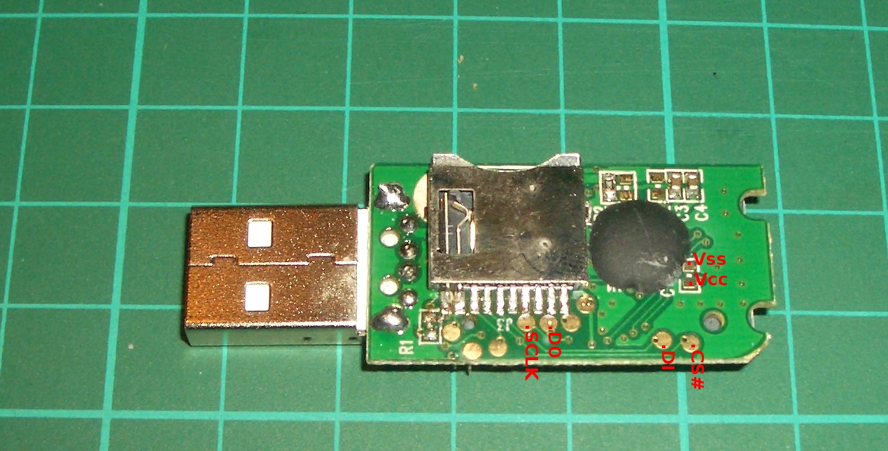
For those who are searching for a cheap SD-card socket, maybe this is a solution:
I've tested an Delock USB SD-card reader at reichelt.de (DELOCK 91667, 3,45EUR) and dismantled it, to unveil the secrets. There are some test-pads on the small PCB, where you can solder easily your ribbon-cable and fix it with hot-glue. See test-pad signal description in the attachment (the common SD card slot is on the backside, here only the slot for microSD can be seen):
Of course you should not plug it into an USB slot, when connected to the MIDIbox core. You can for example desolder the USB connector at all...
+ cheaper then raw SD-slot
+ SD card can be changed
+ normal SD card as well as miniSD, microSD can be used
- fiddly thing until all cables are connected
- not so easy to fix into complete MIDIbox assembly (e.g. can not be screwed to housing, since PCB to small)
-
Ciao all,
since this is my very first post here in the forum, I want to say a big T H A N K Y O U guys for this awesome stuff. Almost everything is well documented and it makes fun to fiddle with these DIY projects.
I am currently building my own SEQ V4. The STM core is running well, together with SD card and displays. Everything worked straight on. No need to post questions up to now ...
Now I am thinking about the user interface. I want to have reduced cable spaghetti, so I am interested in the matrix stuff. I want to describe here how I think it is working. Please any enlightened people correct me, if I have misunderstood something:
Talking about hwcfg/wilba vs. his schematic (Esp. thank you for that, Wilba :wink: !):
BLM8X8_DOUT_GP_MAPPING 1
This "1" points to U7 - 1st output SR where OUT0-OUT7 is connected? I can specify with the number in "SR" for each button, which of outputs OUT0-OUT7 is connected? like:BUTTON_PLAY 18 5
18 => pin6 - DOUT6 ?BLM8X8_DIN_SR 2
The "2" points to U2 - 2nd input SR where IN8-IN15 is connected? I can then specify with "Pin" which of IN8-IN15 is used for specific button? like:BUTTON_PLAY 18 5
5 => IN13 ? Similar for the LEDs:BLM8X8_DOUT_CATHODES_SR 1
The "1" also points to U7 - same SR like GP_MAPPING is used for LED matrix? Could be a different one?BLM8X8_DOUT_LED_SR 2
This "2" points to U8 - 2nd output SR where DOUT8-DOUT15 is connected?
Some additional questions:
1) Header 3 for Beat LED, usage of OUT15A is specified anywhere? Or just OUT14A+1? Or dualLED not used / implemented / "fake" ?
2) Encoder always use 2 successive inputs (like IN6/IN7), whereas only IN6 is specified in hwcfg file?
3) What about IN40 for knobs / IN41 for datawheel? Is this specified in hwcfg file? Sorry, I did not get the magic behind this. :logik:
Thanks for any comments, suggestions, answers.
Cheers,
ArnoNym
Line Driver Module PCBs
in Bulk Orders
Posted · Edited by ArnoNym
Hi midiboxers,
I need a pair of line driver modules. I am thinking of starting a production run of the PCBs at OSH Park.
Anyone interested to join? Maybe I could also provide the parts as kit.
Currently I don't have any information about prices / shipping costs yet, so just show your interest for further planning here.
Thanks
arnonym
Edit:
Status:
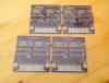
PCBs arrived at my place and few pairs are (still) available for you!
(Two pairs shown.)
Price is 13,80EUR for each pair (One TX and one RX PCB).
Shipping worldwide 3,45EUR.
To definitely buy, please send me a PM which includes:
If you have trouble getting the parts, please let me know, maybe I can send you some of the parts, too.
Buyers / Status:
01. ArnoNym (myself)
02. ArnoNym (myself)
03. SOLD to Phatline (arrived :happy:)
04. SOLD to Phatline (arrived :happy:)
05. SOLD to Phatline (arrived :happy:)
06. SOLD to jab (arrived :happy:)
07. SOLD for Rowan (arrived :happy:)
08. SOLD for Rowan (arrived :happy:)
09. SOLD for Rowan / Lamouette (arrived :happy:)
10. SOLD to Zam (arrived :happy:)
11. SOLD to Zam (arrived :happy:)
12. SOLD to WilHelm* (arrived :happy:)
13. SOLD for Warpboy (arrived :happy:)
14. SOLD for Warpboy (arrived :happy:)