

Lamouette
-
Posts
369 -
Joined
-
Last visited
-
Days Won
4
Content Type
Profiles
Forums
Blogs
Gallery
Posts posted by Lamouette
-
-
Hello, no more time to DIY !
Midibox Stuff for GIVEWAY/TK :
All this stuff is to give, just pay for the shipping, and please give something to TK as payment !
.thumb.JPG.35820daa3773a107d893b71b796183d7.JPG)
.thumb.JPG.c974023eb4cc1b77bb2980258c77e3f1.JPG)
-
On 13/01/2020 at 3:20 AM, dwestbury said:
Hello everyone... Almost done with my first ever MB-6582 build... Been working on it intermittently for an embarrassingly long time, but finally in the home stretch. Wondering if anyone knows where I could get this LCD window part? https://youtu.be/WIup9BhivuY (the part makes it's first appearance @ 1:35)
edit: perhaps @kHz-tone could advise?
Cheers!
Hello, i have still one in a box, not sure if it is the good one for hole dimensions : 82,5x31, is it the good one ?
-
 1
1
-
-
Love the squared led matrix !
-
1
-
-
Ok, all is working like it should be i haven't connected everything yet.
One questions.
I use a TPD and the CV/GATE/CLOCK/TRIGGER side by side.
TPD is connected and powered by the SEQ PSU, which is a PSU with no connection to ground. (i will have to connect the CORE_STM32F4 ground to it)
I use my eurorack power supply to power the AOUT_NG, Only the +12V/GND/-12V
If i understand correctly, on the AOUT, the GND will be different from 5V and +12/-12V.
Can it be a source of problems like ground loops ?
Is there a problem about removing the +5V and GND from the J1 connector on the AOUT_NG and power it with the eurorack PSU ?
By writing this expect another problem, GATE/CLOCK/TRIGGER, come from a DOUT, which have is proper ground so anywat i will get a ground loop ?
Thanks for your asnwer !
EDIT : (another thinking)
I have a SEQV4 PSU which provide +12/-12V so i can power everything from it, but, same problem, i will have ground loops between my eurorack PSU,adn the SEQ PSU, when i will connect a jack between CV/GATE/CLOCK/TRIGGER jack's and an input of my modular ?
-
Thanks for your answer ! I resolved my problems, and it is now working, but i don't understand what i did, led was always lit, i shuted down, and re power on my SEQ, and it was working perfectly ? Really strange behavior.
But it was really interresting to test it. i realise how i loved to build kits, but how it is bad to build something you don't understand.
I read a lot yesterday about simple components, and decided to buy a book to learn deeply what i am doing, i suppose this is the next DIY step. but after 4 years, i really need to understand. i also realise how, i hated the electricity at the school, and haven't remembered anything !
So i restart from nothing, and i feel happy to learn htings !
Sorry for the philosophical post.
To explain, i have a DOUT on a seperate PCB, i will build the gates led on a separate breadboard, and attach it on the back of my eurorack panel, with the AOUT _NG, and the TPD.
-
Hi,
I continue here to get about my problems.
So, i made a separate eurorack panel with a TPD, and the CV outputs ( CV/Gate, / clocks / triggers)
I want to add leds for the gate outputs.
I checked some schematics about how it is done. (Especialy Hexinverter midi2cv, Yusynth, and Altitude euro Aout here on midibox)
i understand how it works, but i am not able to get it working.
Some data :
Gate Voltage mesured : 4.8V
Leds : 20mA 1.85V ( so 470R resistor)
Transistor : 2N3904
If i understand this is a NPN, so closed by default, and it will opens only when a bit of current is flowing, (current provided by the gate)
But the led is always lit.
Should i ad a resistor between to leg to create a kind of fake load ?
-
Don't want to hijack the thread, but i tried the schema, with the good value for my leds, but impossible to get it working.
i have 4.8V at the gate output, and used 470R resistor for my led.
The datasheet for the BC547 say : Emitter-Base Voltage 6V, is my gate voltage to low to open it ?
-
I already did the front panel, and don't want to add a specific DOUT only for this.
I will use Altitude value and check what happens !
-
Hello, altitude, i am on the way to add leds to my gate outputs.
Are you using BC547 as transistor ?
i try to understand how it works, i checked shematics of the midi2CV of hexinverter, some yusynths pcbs, and yours , you all use a transistor, but no one use the same way to accomplish this (maybe it is the basics, sorry if it is THE noob question).
-
Still interrested too !
-
Don't you need to add a diode (like a 1N4148) after the resistor after the 595 to protect it in case of putting a voltage on the cv/gate/trigger/clock accidentally ?
-
Thanks a lot Hawkeye, you have been a really great helper !
Now i have to work the case, but that should be easier for me.
I will keep my thread updated, it could be a great help for someone like me who strart from nothing !
And finnaly it is funny as the first pcb i ever solderd (a DOUT), is the last i added to my build ! it was fun to check my first solder :)
-
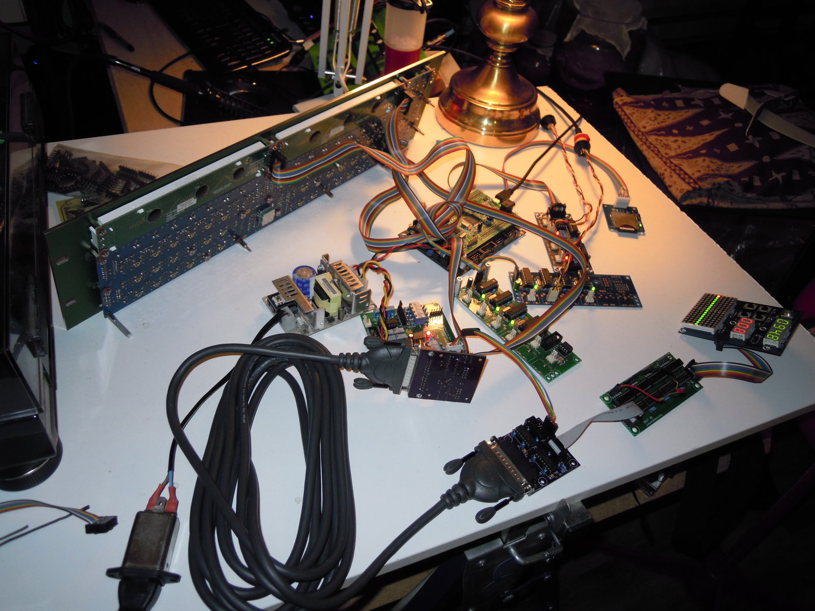
Hell yeah, after huge reading, IT WORKS !!!!!!!!!!!!!!

So after a long story, i just finished the electronics, a picture is needed to immortalise the moment, really, a great moment !

-
1
-
-
This is really helpfull, thanks for doing this !
-
I trided to modifiy the shift register number, but it is not working :
As the TPD in normal connection, is connected to 5 6 7 8 9 10, i suppose the shift register 1 2 3 4 already used by the wilba panel. (1&2 by wilba BLM, and 3&4 by BPM digit)
I tried to put the TPD at the end of the chain, to avoid problems, so :
Original config :
# See also http://www.midibox.org/dokuwiki/doku.php?id=tpd_pcb
##################################################

# set to 1 or 2 to enable the relative track position display
# 0: TPD disabled
# 1: TPD enabled - columns are cathodes, rows are anodes
# 2: TPD enabled - columns are anodes, rows are cathodes
TPD_ENABLED 2

# define the DOUT shift register to which the columns are connected (0=disabled)
TPD_COLUMNS_SR_L 10

# for a 16x16 TPD: define the SR to which the right columns are connected (0=disabled, use only 8x8 TPD)
TPD_COLUMNS_SR_R 7

# define the DOUT shift register to which the green LED rows are connected (0=disabled)
TPD_ROWS_SR_GREEN_L 8

# define the DOUT shift register to which the right green LED rows are connected (0=disabled, use only 8x8 TPD)
TPD_ROWS_SR_GREEN_R 5

# define the DOUT shift register to which the red LED rows are connected (0=disabled)
TPD_ROWS_SR_RED_L 9

# define the DOUT shift register to which the right red LED rows are connected (0=disabled, use only 8x8 TPD)
TPD_ROWS_SR_RED_R 6


##################################################
# CV and Gate/Trigger/Sync Setup
##################################################

# AOUT interface now selected in CV Configuration Menu and stored in MBSEQ_GC.V4 file
# please scroll through the menu to find this page!

# the 8 CV gates can be assigned to a shift register (0=off, 1-32: number of shift register):
# - 1st CV Gate available at DOUT SR output D7
# - 2nd CV Gate available at DOUT SR output D6
# - 3rd CV Gate available at DOUT SR output D5
# - ...
# - 8th CV Gate available at DOUT SR output D0
CV_GATE_SR1   0

# and DIN Clock Outputs can be assigned to a shift register as well (0=off, 1-32: number of shift register):
# D7..D0 will output individual clock or start/stop signals which can be configured in the CV configuration page
CLK_SR        0

# additional gate triggers are available on common digital output pins of the
# DOUT shift register chain - they are assigned to AOUT channel #16 (Note C-1, C#1, D-1, ...)
# define the shift registers which should be used here (each provides 8 gates)
# Note that SRs assigned to this function cannot be used as LED outputs (exclusive function)
# Allowed values: 1-32, 0 disables the function, all other values invalid and not allowed
DOUT_GATE_SR1   0
DOUT_GATE_SR2   0
DOUT_GATE_SR3   0
DOUT_GATE_SR4   0
DOUT_GATE_SR5   0
DOUT_GATE_SR6   0
DOUT_GATE_SR7   0
DOUT_GATE_SR8   0

# if set to 1, the additional DOUT "gates" will send 1mS pulses
# useful for analog drums
DOUT_1MS_TRIGGER 0
Modified config :
# set to 1 or 2 to enable the relative track position display
# 0: TPD disabled
# 1: TPD enabled - columns are cathodes, rows are anodes
# 2: TPD enabled - columns are anodes, rows are cathodes
TPD_ENABLED 2

# define the DOUT shift register to which the columns are connected (0=disabled)
TPD_COLUMNS_SR_L 14

# for a 16x16 TPD: define the SR to which the right columns are connected (0=disabled, use only 8x8 TPD)
TPD_COLUMNS_SR_R 11

# define the DOUT shift register to which the green LED rows are connected (0=disabled)
TPD_ROWS_SR_GREEN_L 12

# define the DOUT shift register to which the right green LED rows are connected (0=disabled, use only 8x8 TPD)
TPD_ROWS_SR_GREEN_R 9

# define the DOUT shift register to which the red LED rows are connected (0=disabled)
TPD_ROWS_SR_RED_L 13

# define the DOUT shift register to which the right red LED rows are connected (0=disabled, use only 8x8 TPD)
TPD_ROWS_SR_RED_R 10


##################################################
# CV and Gate/Trigger/Sync Setup
##################################################

# AOUT interface now selected in CV Configuration Menu and stored in MBSEQ_GC.V4 file
# please scroll through the menu to find this page!

# the 8 CV gates can be assigned to a shift register (0=off, 1-32: number of shift register):
# - 1st CV Gate available at DOUT SR output D7
# - 2nd CV Gate available at DOUT SR output D6
# - 3rd CV Gate available at DOUT SR output D5
# - ...
# - 8th CV Gate available at DOUT SR output D0
CV_GATE_SR1   5

# and DIN Clock Outputs can be assigned to a shift register as well (0=off, 1-32: number of shift register):
# D7..D0 will output individual clock or start/stop signals which can be configured in the CV configuration page
CLK_SR        6

# additional gate triggers are available on common digital output pins of the
# DOUT shift register chain - they are assigned to AOUT channel #16 (Note C-1, C#1, D-1, ...)
# define the shift registers which should be used here (each provides 8 gates)
# Note that SRs assigned to this function cannot be used as LED outputs (exclusive function)
# Allowed values: 1-32, 0 disables the function, all other values invalid and not allowed
DOUT_GATE_SR1   7
DOUT_GATE_SR2   8
DOUT_GATE_SR3   0
DOUT_GATE_SR4   0
DOUT_GATE_SR5   0
DOUT_GATE_SR6   0
DOUT_GATE_SR7   0
DOUT_GATE_SR8   0

# if set to 1, the additional DOUT "gates" will send 1mS pulses
# useful for analog drums
DOUT_1MS_TRIGGER 0
But i got nothing on the TPD... Any thoughts ?
The TPD have 9 Shift register but i can only see 6 assigned on the MBSEQ_HW.V4
-
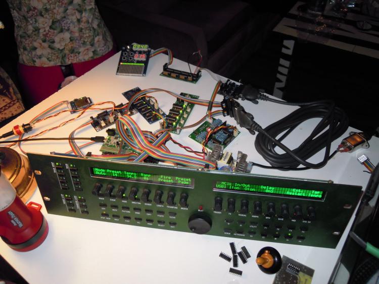
Hi there, some news on my side !
I have now installed a proper ubuntu on a disk partition, and could do some make files without any problems, i really enjoy this OS, so well done on your side guyz

For my SEQV4 :
SEQ is working
2 Quad-IIC working
Line driver working
Aout_NG working
TPD Working

So it is a long road i did, and i am close to the end of the project ! Thanks a lot for you awesome help, and you really friendly behavior ! I learned a lot about different things, i am now a proud soldereing guy, but i know i have lack of electronic and programming knowledge ! Also, speaking in english everytimes here helped me a lot to improve my language !
But the road is not ended yet !
I want to use the line driver to make a separate eurorack module, which would include, a TPD, the AOUT_NG for the cv, and 1 or 2 DOUT for the gate/trigger/clocks.
Here is my question, i read about problem with the TPD not at the end of the DOUT chain.
It is not a problem to connect 1 or 2 DOUT on J2 of the LINE DRIVER RECEIVER, and plug the TPD at his end ? (if i assign the correct Shift rehister number) ?
-
You need to get the PIC16F88 for the 2nd quad IIC burned with this firmware :
http://midibox.org/forums/applications/core/interface/file/attachment.php?id=11978
And you will have to change some line on your midibox firmware
mios32_config.h
#define MIOS32_USB_MIDI_NUM_PORTS 8
and you connect both boards in series, like this :

Have fun !
-
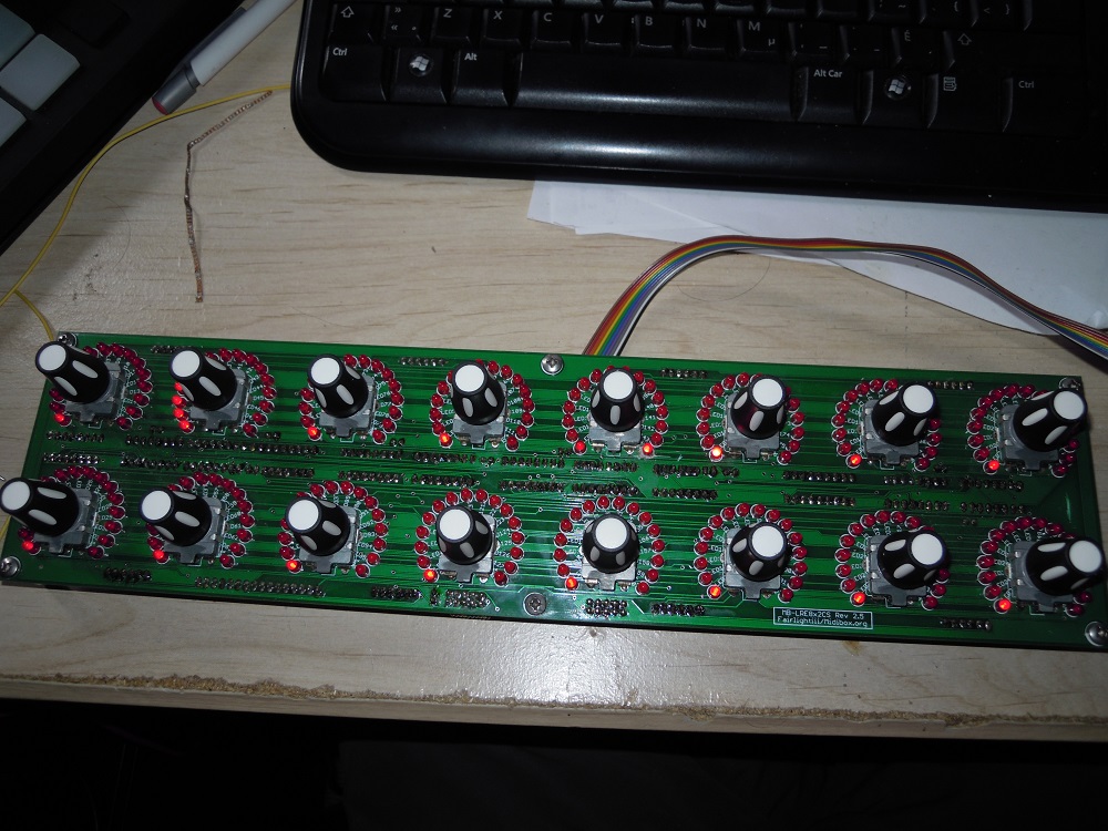
Hello there,
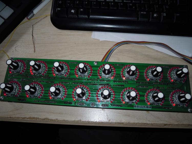
I have one MB-LRE8x2CS PCB version 2.5 to give.
all the ledrings works as expected but the number 9, i tried to troubleshoot it, but i cannot put the finger on what's wrong with it.
i will keep the ICs, and knobs.
2 Condition :
1) i just want to be sure i cannot found a replacement one so i will not give it once i have another one.
2)You pay the shipping, i live in Canada, so north america will be cheaper for you !
-
yes, i had understoood this, thanks for the explain.
and yes, i am pretty sure this is a scratch problem with the soldermask....
Evrytime the 16th of the faulting ledring is lit.i removed the coper all around, but it is still the same
if i turn the encoder until the 16led normally lit, all the other led have a really little brightness, once i pass the 15th , the 16th stop working and no other one is lighting
-
ok, if i understand correctly, and after continuity check, when the 16th led of the ledrings 11/12/13/14/15 are lighting they are creating a short on the led 16 on the ledring 9
-
and same problem... i don't understand...
-
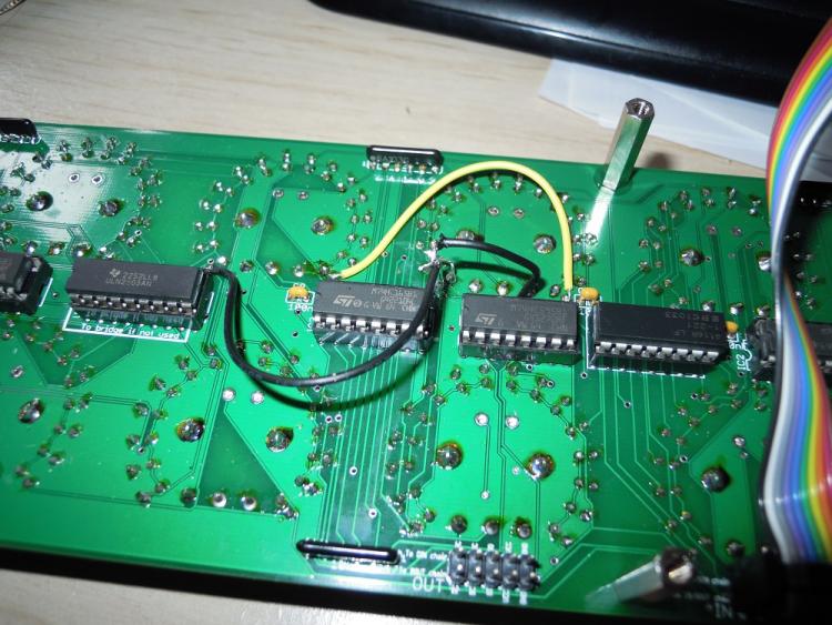
oh, no i forgot it, but anyway, all should have had the same state. i am redoing all the solder point of the ICs. i keep you updated ! Thanks !
-
i removed the ULN2803, i used direct linking, now : all the 16th led of the ledrings 11/12/13/14/15 are lighting in continue.
and if i move any encoder, i can see all the led lighting really low all around the led ring.
-
i am using the uln2803
.JPG.70af516e7a9d6ed8db562cb4546ee5bf.JPG)
.JPG.0bdc972cac6002838d7f5af2215260fd.JPG)


Giveway for TK, last bits, take them please !
in Fleamarket
Posted
Up, take the last bits please !