Lamouette
-
Posts
369 -
Joined
-
Last visited
-
Days Won
4
Recent Profile Visitors
11,211 profile views


Lamouette's Achievements
MIDIbox Tweaker (3/4)
7
Reputation
-
Up, take the last bits please !
-
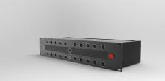
Hello, no more time to DIY ! Midibox Stuff for GIVEWAY/TK : All this stuff is to give, just pay for the shipping, and please give something to TK as payment !
.thumb.JPG.35820daa3773a107d893b71b796183d7.JPG)
.thumb.JPG.c974023eb4cc1b77bb2980258c77e3f1.JPG)
-
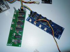
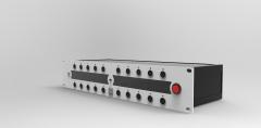
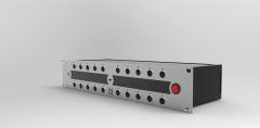
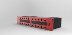
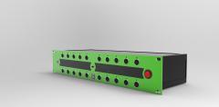
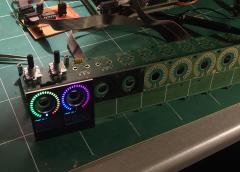
Somes photos about the midiboxing life
-
-
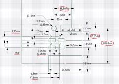
Hello, i have still one in a box, not sure if it is the good one for hole dimensions : 82,5x31, is it the good one ?
-
Love the squared led matrix !
-
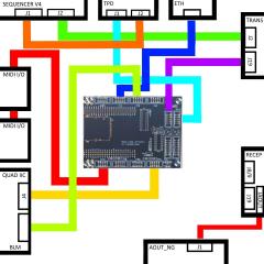
Ok, all is working like it should be i haven't connected everything yet. One questions. I use a TPD and the CV/GATE/CLOCK/TRIGGER side by side. TPD is connected and powered by the SEQ PSU, which is a PSU with no connection to ground. (i will have to connect the CORE_STM32F4 ground to it) I use my eurorack power supply to power the AOUT_NG, Only the +12V/GND/-12V If i understand correctly, on the AOUT, the GND will be different from 5V and +12/-12V. Can it be a source of problems like ground loops ? Is there a problem about removing the +5V and GND from the J1 connector on the AOUT_NG and power it with the eurorack PSU ? By writing this expect another problem, GATE/CLOCK/TRIGGER, come from a DOUT, which have is proper ground so anywat i will get a ground loop ? Thanks for your asnwer ! EDIT : (another thinking) I have a SEQV4 PSU which provide +12/-12V so i can power everything from it, but, same problem, i will have ground loops between my eurorack PSU,adn the SEQ PSU, when i will connect a jack between CV/GATE/CLOCK/TRIGGER jack's and an input of my modular ?
-
Thanks for your answer ! I resolved my problems, and it is now working, but i don't understand what i did, led was always lit, i shuted down, and re power on my SEQ, and it was working perfectly ? Really strange behavior. But it was really interresting to test it. i realise how i loved to build kits, but how it is bad to build something you don't understand. I read a lot yesterday about simple components, and decided to buy a book to learn deeply what i am doing, i suppose this is the next DIY step. but after 4 years, i really need to understand. i also realise how, i hated the electricity at the school, and haven't remembered anything ! So i restart from nothing, and i feel happy to learn htings ! Sorry for the philosophical post. To explain, i have a DOUT on a seperate PCB, i will build the gates led on a separate breadboard, and attach it on the back of my eurorack panel, with the AOUT _NG, and the TPD.
-
Hi, I continue here to get about my problems. So, i made a separate eurorack panel with a TPD, and the CV outputs ( CV/Gate, / clocks / triggers) I want to add leds for the gate outputs. I checked some schematics about how it is done. (Especialy Hexinverter midi2cv, Yusynth, and Altitude euro Aout here on midibox) i understand how it works, but i am not able to get it working. Some data : Gate Voltage mesured : 4.8V Leds : 20mA 1.85V ( so 470R resistor) Transistor : 2N3904 If i understand this is a NPN, so closed by default, and it will opens only when a bit of current is flowing, (current provided by the gate) But the led is always lit. Should i ad a resistor between to leg to create a kind of fake load ?
-
Don't want to hijack the thread, but i tried the schema, with the good value for my leds, but impossible to get it working. i have 4.8V at the gate output, and used 470R resistor for my led. The datasheet for the BC547 say : Emitter-Base Voltage 6V, is my gate voltage to low to open it ?
-
I already did the front panel, and don't want to add a specific DOUT only for this. I will use Altitude value and check what happens !
-
Hello, altitude, i am on the way to add leds to my gate outputs. Are you using BC547 as transistor ? i try to understand how it works, i checked shematics of the midi2CV of hexinverter, some yusynths pcbs, and yours , you all use a transistor, but no one use the same way to accomplish this (maybe it is the basics, sorry if it is THE noob question).
-
 Still interrested too !
 -
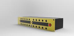
 Oh yeah, looks so good !
 -
Don't you need to add a diode (like a 1N4148) after the resistor after the 595 to protect it in case of putting a voltage on the cv/gate/trigger/clock accidentally ?
-
Thanks a lot Hawkeye, you have been a really great helper ! Now i have to work the case, but that should be easier for me. I will keep my thread updated, it could be a great help for someone like me who strart from nothing ! And finnaly it is funny as the first pcb i ever solderd (a DOUT), is the last i added to my build ! it was fun to check my first solder :)
.JPG.70af516e7a9d6ed8db562cb4546ee5bf.JPG)
.JPG.0bdc972cac6002838d7f5af2215260fd.JPG)
.JPG.3243d7a46089ee68ea65eaac197dd44e.JPG)
.JPG.20876c8c92799c4cb61e536c9e5e3895.JPG)
.JPG.a5f38eb17860fa1ef50a510b1afdfeff.JPG)
.JPG.4d6ef481f5d58c5a871df14e84f7d314.JPG)
.JPG.4dbff3c13484ad51a9c3aed63300f355.JPG)
.JPG.99e47a11fce2ed40ad54ced95758be4d.JPG)
.JPG.7772b3b19234f34db8e41c6e2c88ab54.JPG)
.JPG.e6f00073d3d9013199078ef225090cc7.JPG)
.JPG.bc954a6c06f6c3017aedc22cae36b281.JPG)
.JPG.3a252eb18c2268f6fe421afe376f0585.JPG)