

Jay Beckham
-
Posts
46 -
Joined
-
Last visited
Content Type
Profiles
Forums
Blogs
Gallery
Posts posted by Jay Beckham
-
-
I also disconnected the #0 and #1 still isn't detected by MIOS Studio
-
One that is working is a 0 for the ID. The other was programmed to a 1. I got them from Smash TV and he apparently set them up.
-
I have two CORE8s for my organ. The #0 is working fine and has 4 DIN cards attached for the first and second manual of my organ.
The second one we are trying to setup for a third manual, pedals, and pistons. I had assistance from Graham Goode who is very knowledge and we created and loaded the file using MISIO128. It also has 4 DINs attached. I have tested the DINs and they are fine and the manual works from a continuity viewpoint. I did attach a LCD to the Core and don't get the READY message that I should get. Also using MISO Studio set to second Midi input and don't get any keys detected.
Also #0 is plugged into a CakeWalk Input 1 and #1 is plugged into it's Input 2. Switching cables indicates the CakeWalk works. So it seems I am back to the CORE8. I obtained it from Smash TV a long time ago.
We don't know what to do now.
Thanks, Jay Beckham
-
Is SmashTV still around? How do i contact him?
Thanks
-
I may need a third Core 8 for my Midi. I got kits from SmashTV for the first two and the DIN boards.
Thanks
-
Currently my two manual organ is running fine. Pedals have not been wired yet but a third keyboard will be wired shortly. I currently have four DIN boards attached to one Core board by SmashTV. I have three additional DINs attached to 01 Core board. I am ready to merge the 00 and the 01 core. The gentleman that was helping me via email has passed away. So I am at a loss of what to do next. I do have the second Midi cable. I also have the MidiStudio software and kind of remember how to use it. Can anyone help?
Thanks, Jay Beckham.
-
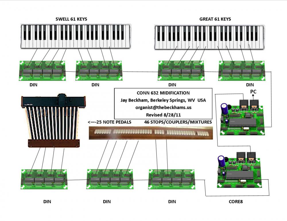
Each of my core8 support four din boards. Each DIN supports 32 inputs. So I have purchased one more DIN for a total of eight. 8 * 32 = 256. So three manuals is 3 x 61 = 183. which is 6 of the DIN boards. One DIN for my pedals and the other one for toe pistons and combinations.
Core Boards First Pin Last Pin Use DINS CORE8 0 1 61 Manual 1 1, 2 Beckham 0 62 64 NC 65 125 Manual 2 3, 4 126 128 NC CORE8 1 1 32 Pedals 5 Beckham 1 33 45 Combinations 6 46 64 Pistons 65 125 Manual 3 7,8 126 128 NC NC Already have two combination boards of six each to mount on the front of my keyboards, a DIN in the mail, and my third manual arrives tomorrow.
Jay
-
I need one additional DIN for my midification of an old Conn. Either the board, the kit (Smash TV), assembled, or the files to make the board or a schematic.
Adding a third keyboard to my setup and no room left on my 7 DIN boards.
Thanks
Jay
-
Thanks for the reply. I will try this tomorrow and let you know what I find out.
-
Below is a posting I made in the Forum under MidiBox Tools and MISO Studio:
I have built two CORE 8 and seven DIN cards from Smash TV. A friend layed out my Hex files and others and walked me through loading them into my CORE 8s. I have wired up two manuals and connected them to the first four DINs. He built the HEX files and the others to fit my two manual old Conn. The #0 CORE is for the two manuals and the #1 CORE is for the pedals and stop tabs. I have also loaded the St. Anne's free version to my Win 8 PC. All manual keys work properly except for the E-1 on the swell. In watching the output I noticed the E-1 shows Channel 7 rather then Channel 1. So I need to correct this but don't know how. My friend is very ill and can not help me at this time.
I have MIOS Studio on the PC but other than monitor the keys I don't have a clue. It would appear to me that the key is incorrectly listed in the file that is loaded on the CORE. I do recall using some program to make minor changes to the codes, but don't recall what or where is was or how to do it.
All I know is to run a cable from the CORE Out to MIDI In on my USB Midi device and also run a cable from the CORE In to MIDI Out on the USB Midi.
Can anyone point me in the right direction? I did download the "tutorial" on MIOS Studio but that isn't much help. More confusing then helpful.
I am located in the US in Berkeley Springs, WV. My friend was in California and he send me the files and walked me through over the phone. The files I have are:
HEX FILES: device_id_00, device_id_01, device_id_02, device_id_03, main_swell_3, and setup_midio128 all with ".hex"
MISC: Beckham 0.syx, Beckham 1.syx, midio128_v2_2b.zip, MIOS_Studio.exe
Any help would be greatly appreciated. I am presently wiring the pedals and may use a touch screen for the stops and couplers.
Jay Beckham
-
I have built two CORE 8 and seven DIN cards from Smash TV. A friend laid out my Hex files and others and walked me through loading them into my CORE 8s. I have wired up two manuals and connected them to the first four DINs. He built the HEX files and the others to fit my two manual old Conn. The #0 CORE is for the two manuals and the #1 CORE is for the pedals and stop tabs. I have also loaded the St. Anne's free version to my Win 8 PC. All manual keys work properly except for the E-1 on the swell. In watching the output I noticed the E-1 shows Channel 7 rather then Channel 1. So I need to correct this but don't know how. My friend is very ill and can not help me at this time.
I have MIOS Studio on the PC but other than monitor the keys I don't have a clue. It would appear to me that the key is incorrectly listed in the file that is loaded on the CORE. I do recall using some program to make minor changes to the codes, but don't recall what or where is was or how to do it.
All I know is to run a cable from the CORE Out to MIDI In on my USB Midi device and also run a cable from the CORE In to MIDI Out on the USB Midi.
Can anyone point me in the right direction? I did download the "tutorial" on MIOS Studio but that isn't much help. More confusing then helpful.
I am located in the US in Berkeley Springs, WV. My friend was in California and he send me the files and walked me through over the phone. The files I have are:
HEX FILES: device_id_00, device_id_01, device_id_02, device_id_03, main_swell_3, and setup_midio128 all with ".hex"
MISC: Beckham 0.syx, Beckham 1.syx, midio128_v2_2b.zip, MIOS_Studio.exe
Any help would be greatly appreciated. I am presently wiring the pedals and may use a touch screen for the stops and couplers.
Jay Beckham
-
Hi Pete,
if the keyboards are not standard in any way I guess that you are definitely the best source of information for Jay.
Regarding SAMs: As part of above linked forums thread I have now posted a complete solution for SAMs if you would upgrade to the STM32F4 and would use the NG firmware. My solution uses the standard DOUT boards. They need to get modded by connecting the ground pin of the ULN2803 to the board ground as well as connecting the flyback diode pin to the unconnected terminal of the header. I connected the ground of all boards to the 12V/25A PSU (SAMs were designed for 15V but work fine with 12V) and the flyback diode wires + the common positive to the positive output of the PSU. If you always wire the off and on solenoids for a SAM in succession you won't get into trouble with the current rating of the darlington array as only a maximum of 4 solenoids can get activated at the same time.
Very important though, this set up only works for common positive SAMs.
cheers
Mathis
From your description of your Dout modifications I had a good idea what you did. Good that you posted the pictures so others can relate to your change. I also did this for another project. I went ahead and took a picture of my layout to help indicate what I did. You did it the right way with having the Dout boards very close to each other. When I do mine, I will also put the Core CPU as close a possible to the Dout boards. As you can see I took all the power related + and - voltages to separate connections so they can be connected as needed in the specific application. There is a jumper that can be used to connect the power ground to the logic ground if not done elsewhere. I included the fly back connections as part of the power spike problems because when the coil is turned off, the current going back into the fly back diode is ~ 0.5amps for a short time, maybe 5-20us as a guess.
My intent is to use my Core CPU as a driver only board (Midi In only). No Midi outputs. I was going to have the SAM's reed switches connections used by another board and the 2 systems wouldn't know about each others switch state. I was going to have Hauptwerk worry about this. I don't know if this will work or not. With your experience, maybe you could enlighten me?I haven't committed myself to using any specific Midi message at this time. Thought I would just start with Note-On/Off first since it is one of the more common used ones that might work with some of the other manufacturers such as Art???? or others. And I will certainly try it with the other cores since USB is the preferred interface.And no telling what John's problem was. A lot of the issues went away when he separated the SAM magnet wires from the reed switch wires that were used in a matrix configuration. And like you suggest, maybe some of the issues might be problem with magnetic coupling between SAMs rather than just wire coupling issues.PeteJay Here
I am finally back and ready to proceed with my Conn 632 conversion. I did learn that 2 or 3 of the rods don't rotate. So i can just solder a wire from the non moving rod contacts to my DIN boards. I am using the 8 wire flat cables and plugs furnished by SmashTV.
One thing I am wondering about is would a LCD be useful in building and testing the work? If so where do I find one? I didn't see them on SmashTV's web site.
Jay Beckham
Attached is my plan.
-
Thanks again for the reply.
I guess I will start building the DINs and then the three Core boards. I will have to decide which computer to use for the organ. I have several spares as I hate to throw computers away!
Jay
-
Pete
I did a search and found MIOS 1 and 2 and a download for Windows XP. Apparently this software tells my computer what key is what note and that sort of thing. I do remember three years ago someone telling about having to create the tables based on my DIN configuration of the keyboards, pedal board, and stops. I did notice that some of my stop tabs are normally open and most of the couplers were normally closed. So I may have to deal with that issue or get a touch screen for my computer and use it for registration. My Conn has no combination or general pistons so I assume a computer touch screen could be used for that? Or I could buy toe pistons for generals?
Jay
-
Pete
What is the MIOS Studio application? I have one of the free organ programs. I also have a Roland cakewalk USB MIDI interface UM-2G and 20 ft Keyboard cable. Also a couple PCs available running Windows XP. Is the MIOS Studio application available for download?
Jay
-
I took another look at the two manuals. On one there is two buss rods that don't move. They are normally open. On the other there are three buss rods that don't move and they are normally open. So I gang the two and the three together for my commons and then attach wires to thoses two and three pins and I have got what i need I believe.
Jay Beckham
james@thebeckhams.us
-
Hi
Thanks for the reply.
First the keyboard contacts are normally open like yours but my rods rotate so they must be locked down some how. I don't recall about the stops but will check on that. I don't think the stops will be a problem as they would be easy to modify it they are normally closed.
I have never assmebled the boards but maybe able to get to that soon. I had another big project that kind of occupied by time.
I had considered tying them all together also. Maybe I should do 10 or 20 notes and see how it goes. The least expensive none piston keyboard I could find so far was $595. I had hoped they were in the $300 range but maybe that is just dreaming.
Based on that pricing of $595 I should at least give it a try.
Jay
-
I have been gone from the forum for a long time. I had purchased the various boards from Smash TV back in 2011. I tried various ways to wire the keyboards (2) for simple switches without success. My wife suggested I just buy two keyboard and not fight it anymore. I have all the boards and cables to wire this organ. Can someone suggest a source of keyboards that won't cost me an arm and a leg. It would nice to have combination pistons, but I can survive without them. I want to end up with a reasonable classical organ.
Thanks
Jay Beckham
james@thebeckhams.us
-
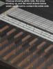
No the felt limits its movement but not in a good way.
Seems that the rod is lined up when the lever points out in line with the holes in the bracket that supports the rod.
I may try and use the cables that moved the lever and just clamp it down using the screw holes that held the cable in place.
It is like an old car choke cable. I can cut it and just use the inside wire and the device on the end that hooks over the lever and clamp it in place with a screw.
When I posted this question several days ago I assumed someone had used the Conn keyboards and knew a bit about them. But I guess that wasn't the case. So I am going to start building my DIN boards and my Cores and attach wires to an octive and see what happens.
I understand that my Cores should already have the software in them when I got them from Smash TV? Is that true?
Thanks
Jay
Does the lever on the end of the bus rod press against the felt when it is the position where the conductive part of the rod contacts the wipers? If so, you might be able to tie the rod in that position with a piece of wire that is looped through those holes to the right in the picture.
-
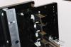
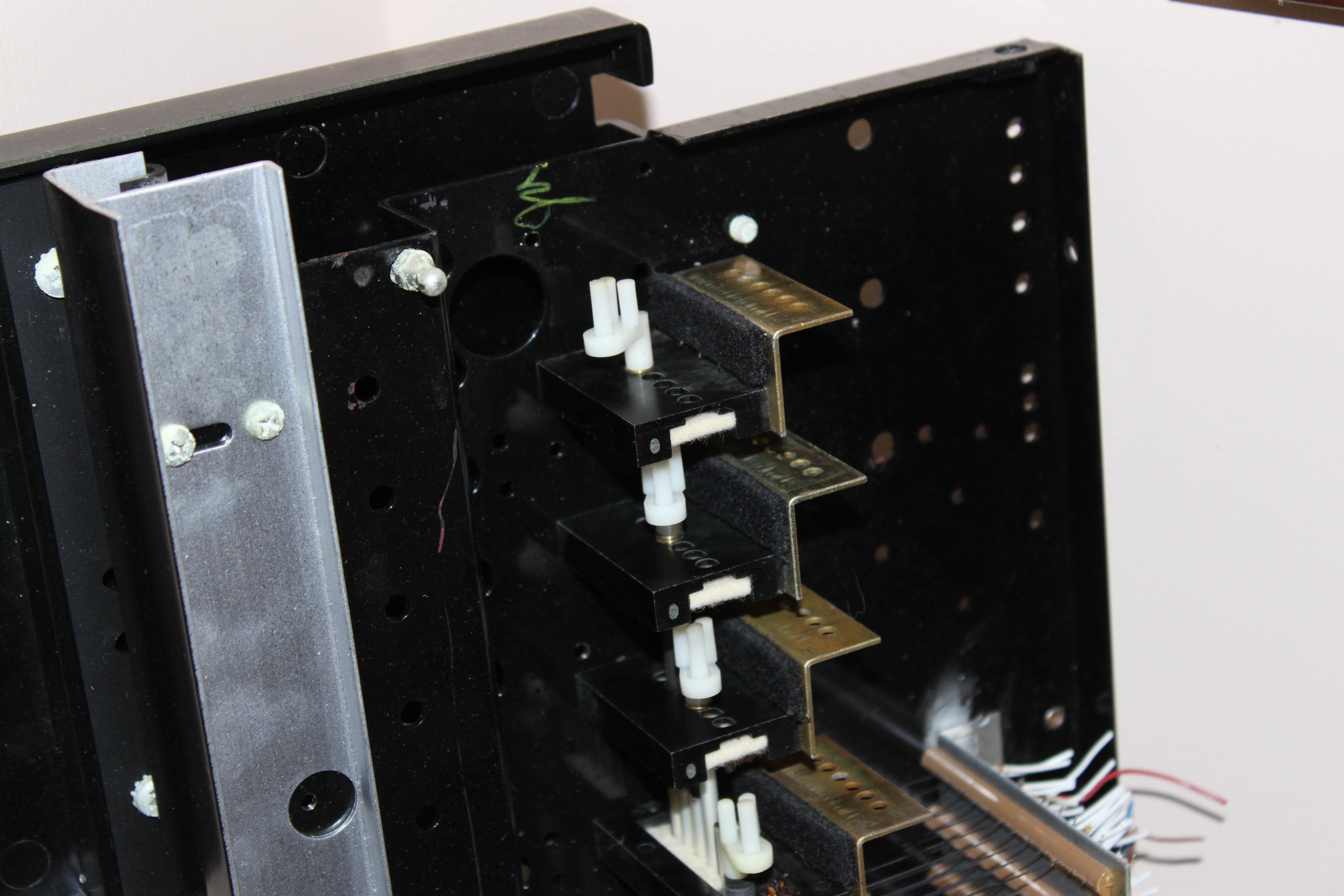
Here is the end with the most rod controls on it. They vary by manual but the white plastic lever and the black metal plate with holes in it are the same.
Can you post a picture of the mechanism that rotates the bus rods?
-
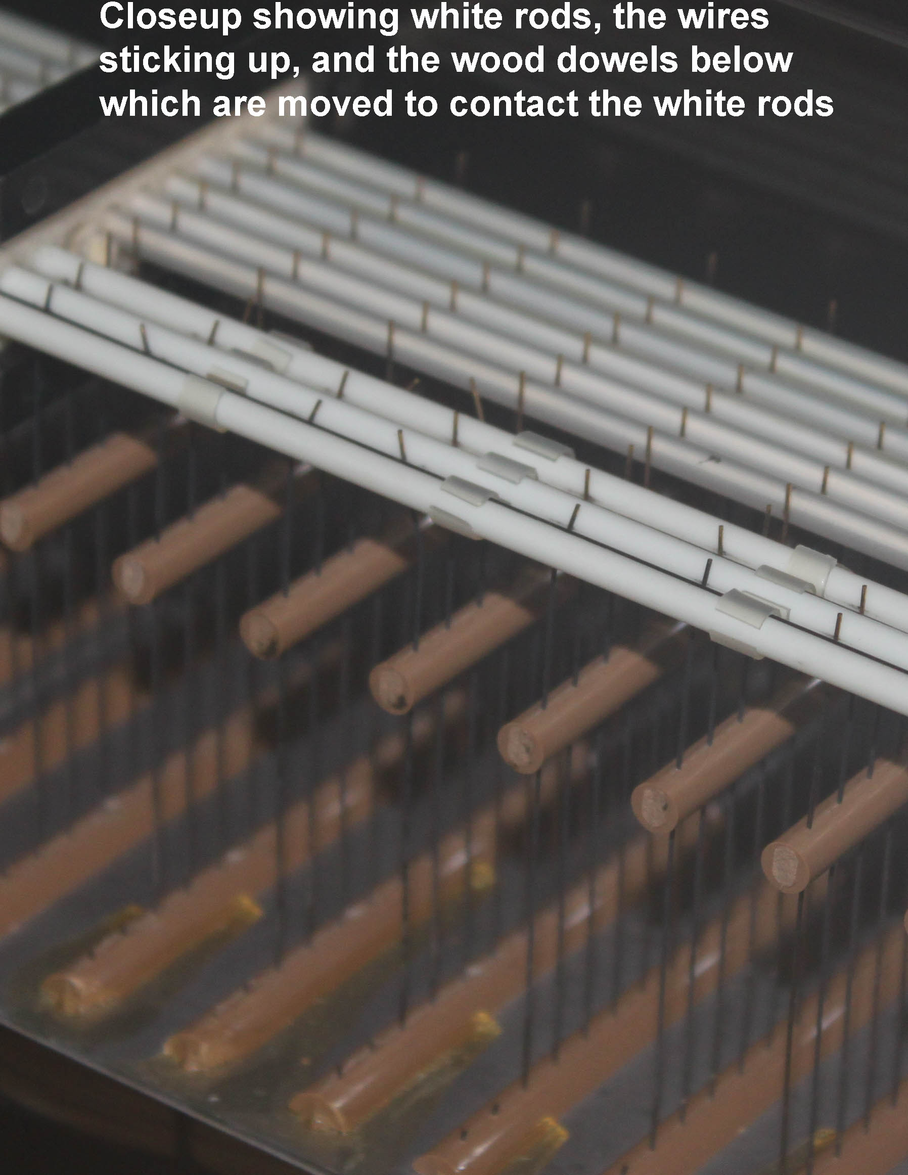
Attached is a picture of the rods and the wiper wires. The first three bus rods have built in resistence so I won't be using them. The other six are just plain metal. The are rotated by certain stop tabs to turn that stop on. So the little wires attached to the wood dowels are moved by the keys. So I need to rotate at least two of the rods and lock them down in some way.
Thanks
Jay
Can you post photos of the bus bars and explain what it is you want to "lock down"? It is likely that no one here has ever even seen a Conn 632. I know I haven't.
-
Hi Jim
I was just covering myself in case the wiper wires would break. So maybe two is enough? Still don't know a good way to lock them down.
Jay
Why do you want to use six bus bars? One should be enough. Maybe two for redundancy.
-
I am getting ready to attach my keyboards to the Midibox DIN boards. Would like some advice as to how to lock down the six bus bars so I can use all six wiper wires for contacts to feed my Midi hardware.
Thanks
-
1. If in the future I want to add Combination Pistons/Buttons would that just involve either left over space on my 7th DIN or the use of a 8th DIN?
2. If I wanted to add SAMS where would I get them and what would I expect to pay?
3. I assume that SAMS would require DOUT boards and would they attach to the Output pins on the Core8?
4. As I recall the CORE8 can support 128 inputs as well as 128 output (via DOUT)?
Thanks
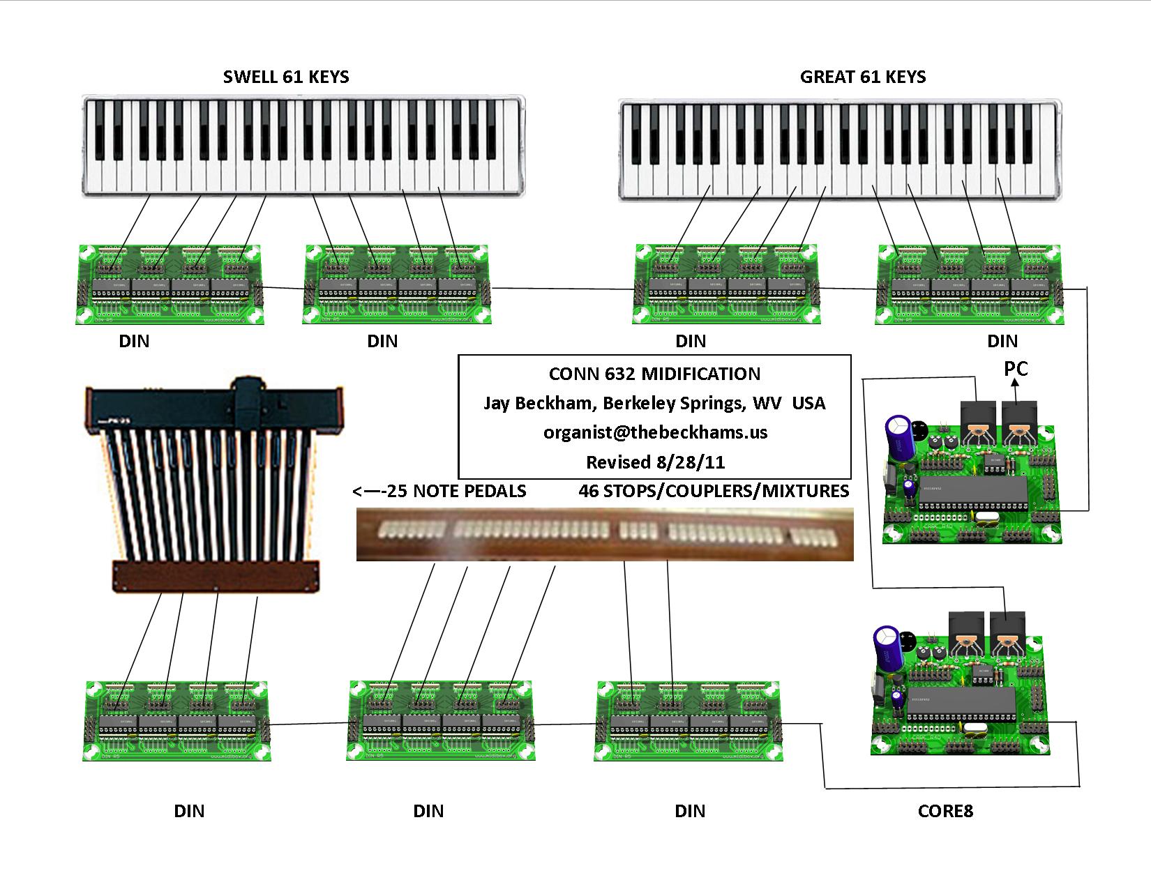
Conn Church Organ Model 632 to MIDI
in MIDIfication
Posted
I have finished converting this CONN's two manuals and added a third manual from a pipe organ. All is working properly. This happened about five or so years ago.
However, now I have wired up the CONN pedal board and am using a MIPC-1A Keyboard/Stop Midi Encoder board. I have MIOS studio 2 loaded and can't remember how to get it to recognize the Pedals hooked to the board.
I got the three manuals to work some years ago, and can't even find any instructions.
If anyone can help I will surely appreciate it.
Jay Beckham
jay@jayandjulie.us