
Signal Integrity for long SRIO chains (MIOS32)

Entry posted by Duggle
2,663 views
Abstract
Discussion of the problems limiting the length of SRIO chains.
Some causes of signal integrity problems in transmission lines are mentioned.
A Working solution is presented.
Introduction
The problems limiting the length (physical length and the number of chips connected) of DOUT shift registers has been canvassed during the development of my Midi Keyboard LED Display (MKLD) project. MKLD Itself is the subject of an upcoming blog article. Suffice it to say for now that the design uses 24x 74HC595 chips to drive a display that covers a 4 octave keyboard. I intend to drive 2 keyboards this way adding up to 48 chips.
A limit of 16 shift register chips in SRIO chains has been arrived at empirically. This has been based on the number of chips (contained in DOUT modules for instance) that can be reliably successfully controlled. MIOS32 can address an arbitrary number however, but problems can and will arise after a certain number of shift registers are attached.
Rudimentary signal integrity for transmission lines
When the clock rate of data is high and the physical length of signal traces in long relative to it, the wave shape of signals can change to the point where the circuit no no longer functions reliably unless special steps are taken in the design to prevent this. In an absolute nutshell: voltage wave reflections due to characteristic impedance changes (particularly at the end of the line) interact with the distributed LRC impedances to produce ringing.
"The crude rule of thumb are that a conductor is electrically long when it exceeds one-seventh of the shortest wavelength of concern, or when the time that the leading edge of a signal takes to travel from the source to the furthest receiver exceeds half of its rise or fall times. " Reference
The article quoted above provides the estimate for a circuit board of 6.7ns/m for speed of signal. So in the case I have encountered with MKLD length of say 4m, signal travel time is around 30ns. The "crude rule of thumb" states that the rise time of my clock signal should not be less than 60ns.
In practise with the MKLD circuit
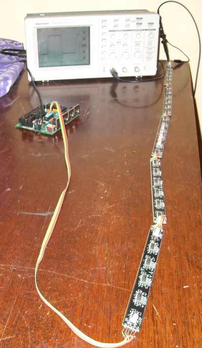
Simply connecting the DOUT port of J8 of the MBHP Core STM32 to the MKLD string of 30 shift registers has worked. But the seeds of a problem are there to see:
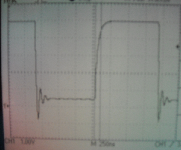
SCLK signal measured at the end of the chain
The falling edge (driven low by the open drain output of the STM32) is rather fast (<~20ns). There is distinct ringing occurring.
Interestingly, the rising edge (driven high by the 220 ohm pullup) is slower (~100ns). No sign of ringing.
The input capacitance of the inputs of 74HC595 is 3.5pF per input. With 30 shift registers, the SCLK line has a total capacitance of (3.5*30)=105pF
The RC time constant (time for a rise/fall of 66% of max/min) is (220*105)ps= 23.1ns. This suggests that the parasitic capacitance (that caused by the ribbon wire and pcb tracks, totalling close to 2m in length) may be more significant.
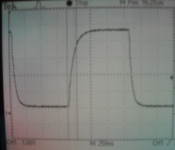
SCLK signal measured at the end of the chain
This is with a series 220 ohm resistor at the source. The falling edge no longer has any trace of ringing.
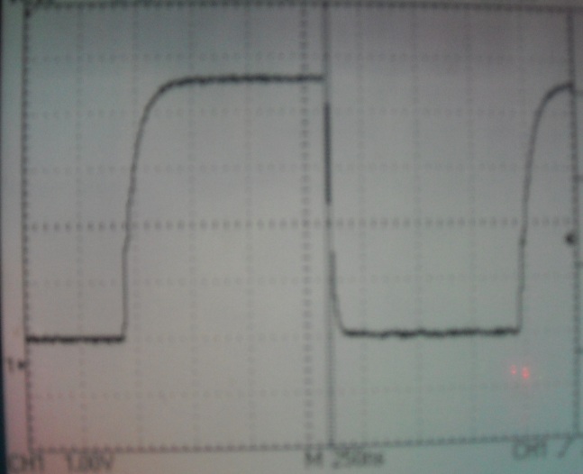
SCLK signal measured at the end of the chain
Using 100 Ohm resistor. Better wave shape. The cursors measure ~20ns fall time. The actual test setup is probably only around 1.5m in signal path length.
Conclusion
It is useful to note that the "solution" here is not impedance matching but rather making use of parasitic capacitance in conjunction with an applied series resistor to slow down the edges of the SCLK signal to the point where transmission line effects are not observed. This is only possible due to the relatively slow clock used by MIOS32. There is no performance hit as the transfer is using DMA. With an update period of 1ms, there is a theoretical limit of nearly 1000 bits of SRIO that may be transferred.
Other points to mention are that the RCLK signal has timing such that it has plenty of time to settle where there are no changes in either DIN In or SCLK. DIN is also physically shorter and is resynchronised with each chip therefore less likely to need a series resistor.
The "Working solution" may or may not work for MIOS8 systems where the bit-banged SRIO is considerably faster clocked. I would suggest smaller series R.
And finally, I'd love to hear from any signal integrity experts on any false statements or assumptions or analysis that is unreasonably flawed. Comments welcome!
Pictures and text © Duggle 2010
1 Comment
Recommended Comments