

GMAprogrammer
-
Posts
72 -
Joined
-
Last visited
-
Days Won
4
Content Type
Profiles
Forums
Blogs
Gallery
Posts posted by GMAprogrammer
-
-
Hey Guys,
in this Thread i Want to Present my first Midibox Project. Not only because it is maybe interesting for others but also to provide met some Help from you guys because im stuck with the Midibox_NG Configuration.
For the better readability i will Write this Post in English so as many of you as possible can give me help and Feedback. Please excuse when i do some mistakes with the language.
So to start at the very Beginning:
With 14 Years i started to work with MA-lightings Control Software GrandMA OnPC (http://malighting.de/) . Some day i though about some sort of hardware controller for it. I started to google for it and found out that theres a possibility to connect the BCF2000 from Behringer to the software and even get the motorfaders to work with a special driver. So i ordered my first BCF2000. Over the time an with the money i got from my lighting jobs i got: Two BCF2000, several Touchscreens, a Novation Launpad and some Griffin Powermate USB Encoders. With this stuff build into a case together with a ripped apart Laptop i got my own first Lighting desk over Midi.
[Picture]This thing does its Job for about 1,5 Years now. The only Problem is that its not running very stable because of the many USB devices connected and the old Laptop in it. So i started looking for a better more custom solution.
I saw several people in the internet doing exactly what i want, a custom hardware midicontroller to control GrandMA OnPC. Some of them even in this Forum but in my first attempts i wanted to go with Doepfer USB64 and another Buttonboard from them. Based on this Boards i designed some PCB Layouts and did them myself in my home workshop but i never get them to run.
[Picture]I got in Contact with another Midiboxer (ChrisK) you can find his Project under ww.notapage.net an he finally convinced me to switch over to Midibox. One of the reasons for that was the fact that the Doepfer Modules would have cost me about 450€ in Total and that the Midibox is way more flexible in its Configuration.
So, throw away everything ive planned till this Point and started a complete new project. With Chris‘ help i understood the Basics of the Midiboxconcept very quick and decided to go with a MIO128 Application to get my Buttons to run and with some MF_NG Modules to get the 12 Faders into the Midibox. Ive used hours and hours to read on Ucapps and make my thougts about how i can build this Projekt. Later this will safe me a lot of time but at this Point i nearly stopped the Project withot even had one Cable soldered.
But i did go on :smile: so now the more interesting Part:
At August Last Year i finally started assembling the first Midibox parts ordered from Smash. From then on there is a continous Progress in the Project.
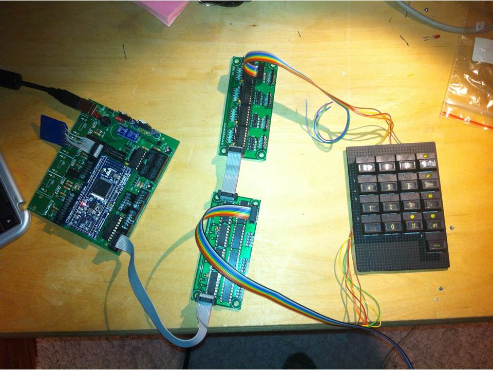
[Picture]My Project basicly base on a big Button Matrix scanned by several DIN_SR and one DOUT_SR. The LEDs in the Buttons are driven by some extra DOUT Modules. And as i said before the Faders are going to be working over 2 MF_NG Modules and maybe the internal Analoge Ports of the Core.
So here are some Pictures of the Building:
So as i got nearly all the Buttons soldered on i started to work at the case. For this i used Autodesk Inventor and some DXF Exports from my Eagle drawings with the Button Layout. With this it was very Easy for me to draw the Frontpannel for example. After ive checked the Frontpannel with some Carboard Prototypes i send them to Cutworks to get the Frontpannel and the Holdpannel lasercutted from them.
So ths is where i stand now i got my Buttons and LEDs to run with the MIO 128 Application and now i want to switch over to Midibox_NG and there is the Problem for me. I first saw the .NGC Config File i just saw CODE!!! It wasnt that bad when i started reading the User Manual but since ive updated to _NG i just had Problems and throwbacks. This is why i write this Post :smile:.
The Questions will be posted in the following posts. Hope you like it until now :smile:
best wishes Alexander
Ok here a bit of my Concept. All Buttons are scanned over a Single DOUT_SR (Number 16) and over the DIN_SR’s (1, 4, 5, 8, 9, 10). The Goal is that every Button can send an own Midievent . So as i understood the .NGC File i have to configure the DIN_MATRIX with the following Command and with „ button_emu_id_offset“ i can force it to use the EVENT_BUTTON to configurate every Button at its own.
DIN_MATRIX n= 1 rows=8 inverted_sel=0 inverted_row=0 sr_dout_sel1= 16 sr_dout_sel2= 0 sr_din1= 1 sr_din2= 0 button_emu_id_offset= 1
DIN_MATRIX n= 2 rows=8 inverted_sel=0 inverted_row=0 sr_dout_sel1= 16 sr_dout_sel2= 0 sr_din1= 4 sr_din2= 0 button_emu_id_offset= 65
DIN_MATRIX n= 3 rows=8 inverted_sel=0 inverted_row=0 sr_dout_sel1= 16 sr_dout_sel2= 0 sr_din1= 5 sr_din2= 0 button_emu_id_offset= 129
DIN_MATRIX n= 4 rows=8 inverted_sel=0 inverted_row=0 sr_dout_sel1= 16 sr_dout_sel2= 0 sr_din1= 8 sr_din2= 0 button_emu_id_offset= 193
DIN_MATRIX n= 5 rows=8 inverted_sel=0 inverted_row=0 sr_dout_sel1= 16 sr_dout_sel2= 0 sr_din1= 9 sr_din2= 0 button_emu_id_offset= 257
DIN_MATRIX n= 6 rows=8 inverted_sel=0 inverted_row=0 sr_dout_sel1= 16 sr_dout_sel2= 0 sr_din1= 10 sr_din2= 0 button_emu_id_offset= 321
So like this:
EVENT_BUTTON id= 64 type=NoteOn chn= 2 key= 0 range= 0:127 offset= 0 ports=1000100000001000
My Problem now is that its not working so MAybe someone can help me with that. The Only thing that happens ist that the first 6 DOUT_SR connected LEDs start to glow.
Any suggestions ?
-
 1
1
-
-
Cool, so i would take 5 Caps with "Fingermulde" in black when its possible. :)
-
Where do you order them? I need some 41mm Top Caps in Black with "Fingermulde". Or can you just order complete sets? best wishes Alexander
-
The 64-bit OS was Windows 8. So do i have any negatvs from not using the driver?
[German]
OK das war vorhin falsch formuliert von mir deswegen nochmal schnell auf Deutsch: Ich hab den 64-bit treiber auf meinem Widows 8 PC versucht zu instalieren dabei kam der Error. Nicht auf einem 32-bit XP das kann ja nicht funktionieren.
Ich habe den 32-bit Treiber unter XP instaliert und da funktioniert der treiber dafür habe ich Porbleme mit dem Filebrowser. Treiber deinstallieren hilft nicht.
gruß Alexander
-
Hey Thorsten,
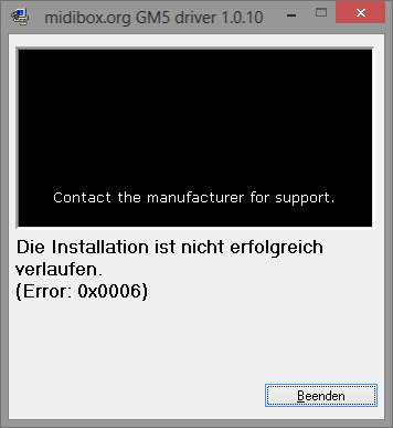
i have tested various combinations. At first there seems to be an issue with the GM5 Driver for 64-Bit. This morning i tested it on my 32-bit maschine there the installation was succesfull.
Ok i tested your new _NG Version on the 32 bit Machine: Same issues with and without the driver.
Best regards
Alexander
Edit: Driver issue 64-Bit Picture
Update: OK under Win8 64-Bit without the driver and your Version of NG it works as it should as far as can say now. I can edit the Files from MIOS Studio.

-
Hey Folks,
Got a small issue with Midibox_NG and cant really say if its a MIOS Studio Error, an Application Problem or a Driver Problem. If im in the wrong Thread with this request please place it where it belongs.
So now the Problem: I just updated my LPC17 Core to newest Version of the MIOS32 Bootloader. Than i installed the newest Version of the Midibox_NG Application to it. Finaly installed the new Driver for WinXP (GM5)
When i now open MIOS Studio it correctly find the Core. all seems to be fine i can send commands to the core, i can enter "msd on" usw.
Now i wanted to use the new Filebrowser to take a look at the Midibox_NG Config files on my SD Card. So i opened and Updated it. I get 4 Files displayed by the Filebrowser i think this is the normal amount. So now i choosed the Default.NGC (Same issue for the Default.NGL) and pressed Edit Text. The Filebrowser starts to load the Files from the Core. After some sec. It freezes and Displays:" No response from MIOS32 core during read Operation!"
I can acces the Files "manually" via SD Card and "msd on" but it would be nice to get the Filebrowser working.
Hope for your suggestions to solve it.
Best wishes Alexander
-
Hallo Thorsten,
Mit Tabelle war die Excel Tabellle gemeint. Hier ist die Einzeltastenconfiguration innerhalb einer Matrix ja durch einen 8x8 Block möglich. Dort werden die Reihen und Spalten von 1-8 gezählt nicht von 0-7. Mir ist einfach nicht ganz klar wie der Zusammenhang von Exceltabelle und den Pins am DOUT/DIN Modul aussieht. Was ich ja letztlich zur genauen Identifkation der entsprechenden Taster wissen muss. (bei mir sind es nicht immer 8x8 Blöcke sonder auch Freiräume dazwischen)
ich weiß welcher Taster welche 2 Pins verbindet kann es aber nicht auf die Exceltabelle umsetzen da es keinen logischen Zusammenhang gibt. Zum. erschließt sich mir keiner. Deswegen dachte ich evtl. kann man da was verbessern indem man das einheitlich benennt.
Wenn die reihen anders herum gezählt werden wäre doch Pin D0 = R0 was in der Excel Tabelle dann R1 entspreechen würde richtig? (vorher: D0 = R7 = R8 in der Excel Tabelle? Vielleicht verstehst du jetzt was ich mit nicht logisch verknüpft meine.)
Wie gesagt das ist jetzt eine Anregung weil ich zum testen meiner Matrix schonmal eben eine Config schreiben wollte und gescheitert bin :D ausprobieren geht nocht nicht mir sind nämlcih die Pfostenstecker ausgegangen und die Taster sind dementsprechend noch nicht verkabelt.
gruß Alexander
-
Hallo Thorsten,
ich hätte noch eine kleine Anregung um die Excel-Tabelle der MIO128 ein wenig zu vereinfachen im Bezug auf die Matrixfunktion. In der Doku siehe -> http://ucapps.de/midio128/midio128_v3_scanmatrix.pdf
werden den Jeweiligen Pins des SRs ja Reihen und Spalten zugewiesen diese werden mit C0-7 und R0-7 bezeichnet. Erste Anregung wäre daher die Reihen und Spalten in der Tabelle auch 0-7 zu nennen.
Das andere ist das in der Doku s.o. bei den DIN Modulen die C0 auch D0 zugewiesen ist R0 aber D7 ich finde dies sehr verwirrend da ich durch diese unregelmäßigkeit keinen direkten Bezug zur Tabelle herstellen kann. Ich denke beide Änderungen zusammen könnten zur Übersichtlichkeit beitragen. So das im Endeffekt der Pin D0 mit der Spalte/Reihe 0 in der Excel-Tabelle logisch verknüpft ist.
gruß Alexander
-
Ich habe nochmal eine schnelle Frage, kann ich mit der Midibox NG auch individuelle Noten in der Matrix zuweisen. Ich habe schonmal entsprechende Stelle in der User Manual gesucht ist das damit gemeint? ->
button_emu_id_offset=<1..4095>
gruß Alexander
-
Hallo Thorsten, Danke für die schnelle Antwort. Ich werde dann wohl auf NG umsteigen! Genügend Programierbeispiele gibt es ja und da ich sowieso noch kaum an der Config Datei gearbeitet habe ist es für mich eifach ,öglich zu wechseln.
LG Alexander
PS: Wo stellt man am besten eine Projektdokumentation ein? Also jetzt Hardwaremäßig ähnlich wie ein Showcase. Denke das wäre ganz gut weil andere Leute enem dann be Problemen realtiv schnell helfen können.
-
Hallo Thorsten, was ist denn deiner Meinung nach sinnvoller? Eine eigene MIO128 bzw. MIO256 Version basteln oder das komplett auf MidiBox NG umswitchen? Nachteile hat man durch die NG Firmware ja keine gegenüber der MIO128 Firmware oder?
gruß Alexander
-
Hallo Thorsten, nur damit du weißt woran es nun lag: Ich war einfach zu blöd die richtigen Wiederstandarrays auf die DOUT Module zu setzen. Statt 220 Ohm habe ich 220kOhm verbaut so kann es ja auch nicht funktionieren. Aber du kennst das ja bestimmt wenn man lange nach einen Problem sucht dann übersieht man oft das offensichtliche ;). Danke trotzdem für deine Antworten es hat mir sehr geholfen das Matrix System noch besser zu verstehen.
Beste Grüße Alexander
-
Hallo Thorsten, ich habe jetzt alles getestet... Leider funktioniert es immer noch nicht. Ich überlege jetzt das ganze Projekt auf einzelverdrahtung umzustellen. Beantworte mir vorher aber bitte noch eine Frage, ist es inzwischen möglich bei der Matrix Tasterspezifische Midinoten zu konfigurieren oder geht es nur über eine Startnote für eine 8x8 Matrix? Ich habe mir hierzu die Excel Tabelle schonmal angeguckt und dort scheinen ja entsprechende Reihen und Spaöten orhanden zu sein.
gruß Alexander
-
Hallo Thorsten, habe das gerade mal versuch nachzustellen dabei bietet sich mir Folgende Situation:
1.Fall Verbindung Pin D0-D7 mit VSS = 8 Noten im MIOS Studio
2. Fall Verbindung Pin D0- D7 vom DOUT Modul mit einem DIN Pin = Keine Reaktion.
Wenn ich "show" eingebe zeigt er mir einen Teil des Patches an aber nicht alles... Wieviel ist immer unterschiedlich. Danach ist der Core nicht mehr zu erreichen Query schlägt fehl! Gleiches Phänomen tritt auf wenn ich mit "msd on" auf die SD Karte zugreife und danach durch "msd off" versuche wieder zum Midi-Betrieb zurückzukehren...
Helfen tut nur ein Ein- und austecken des Cores?
Kann es sein das dieser vielleicht einen Weg hat?
Gruß Alexander
-
Hallo Thorsten, ein SCS habe ich nicht. Da ich vorher noch kein Projekt realisiert habe habe ich leider auch keinen Lagerbestand aus dem ich mir schnell eins zusammen zimmern könnte...
Das mit der default.mio verstehe ich nicht ganz... Kann ich nicht übers Mios Studio jeden beliebigen Patch von der SD Karte laden? Oder babe ich das falsch verstanden?
Ich werde alles was du mir oben gesagt hast sofort ausprobieren. Im Laufe des Abends sollte ich dann ja ein Ergebnis erziehlen.
Gruß Alexander und danke schonmal für deine Unterstützung!
-
Hallo Thorsten,
DIn sowie DOUT Module funktionieren im Standart Betrieb einwandfrei...! Led am DOUt Modul leuchtet wenn ich sie zwischen D7 und VSS halte und dann "set dout all 1" eingebe. Wenn ich beim DIN Modul Vss mit einem D0-7 Pin verbinde empfängt Mios Studio eine Midinote...
die Matrix läuft immernoh nicht. ich habe auch schon versucht das ganze mal mit einem einfachen Kabel zu Brücken aber da tut sich nichts! Die Testplatine habe ich auch shcon komplett durchgemessen die sollte eigentlich so in Ordnung sein.
gruß Alexander
PS: Wenn das mit Der Matrix nicht klappen will werde ich wohl noch einen 2ten Core und ein paar DIN Module brauchen dann wird halt jeder taster einzeln verkabelt.
Hier ist noch die Excel Config wenn es nicht zuviele umstände macht kannst du ja mal drüberschauen aber eigentlich ist alles so eingetragen wie es sein sollte :/
Mir ist eben gerade noch etwas komisches aufgefallen... obwohl der Matrix Patch geladen ist schickt das DIn Modul bei Verbindung von VSS und D0-7 einen Wert ans MIOS Studio. Sagt das irgendwas aus?
-
Hallo Thorsten,
Nein ich habe verschiedene Kombinationen durchprobiert...beim DOUt wäre das natürlich ein Problem ich werde es heute Abend nochmal probieren ! Danke nochmal.
LG
-
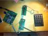
Hallo Leute, irgendwie stehe ich ein wenig auf dem Schlauch! Habe meinen Core mit MIOS Studio laufen die Exceltabele nach dem oberen Beispiel konfiguriert und eine Buttonmatrix zwischen dem ersten DIN/DOUT Schiftregister gesteckt. Leider kommt beim drücken eines Tasters keine Midinote im MIOS Studio an. Hat vielleicht jemand eine Idee woran das liegen könnte? Bilder reiche ich nach sobald ich sie runterskaliert habe kann sie nicht hochladen sie ind zu roß :/.
Danke schonmal gruß Alexander
Hier noch 2 Bilder:
1 Meine Matrix verdrahtung
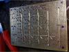
2 Meine testanordnung
gruß Alexander
-
Danke Thorsten,
ich werde mich heute Abend mal daran machen es auszuprobieren. Sobald das Prinzip läuft gibt es auch mehr informationen zum Projekt.
gruß GMAprogrammer
-
HAllo Comuity,
obwohl ich schon einige Zeit leise mitlese muss ich jetzt einmal selbst aktiv werden.
Mein Projekt besteht eigentlich nur aus einer großen Button-Matrix. DIN und DOUT Module und der Core sind fertig Prinzip habe ich auch verstanden. Nun wollte ich testen ob ich das Prinzip für die Matrix richtig umgesetzt habe und habe testweise eine Matrixplatine 4x5 an ein DIN und ein DOUT Modul angeschlossen.
Leider bin ich aber durch die Excel Tabelle nicht so richtig durchgestiegen. Vielleicht könnte mit ja jemand schnell sagen welche Parameter ich in der Exceltabelle ändern muss damit ich eine Matrix zwishcen dem ersten DOUT Modul und sämtlichen DIN Modulen aufbauen kann.
Vielen Dank im vorraus
GMAprogrammer

Project: MA4PC a Midibased Lighting Controller
in MIDIbox NG
Posted · Edited by GMAprogrammer
Here my Config until now. just configurated some buttons and heres also a matrix connection diagram.
The Numbers should be the Button IDs
DEFAULT.rar