

Highcooley
-
Posts
95 -
Joined
-
Last visited
-
Days Won
3
Content Type
Profiles
Forums
Blogs
Gallery
Posts posted by Highcooley
-
-
Wow, 160 bucks on a veroboard

Thanks for the fix, it should work a treat. Giving you feedback asap. Shall I do any testing with different number of DACs or have you already done that?
Best regards, andy
Update: Yep, all working fine now with every reset and power-up I tried with 4 DACs.
 The synth starts to sound cool
Thanks a lot (and secretly hoping that my other issue with the DIO matrix turns out to be a software problem as well)


-
I don't really want to skip CTRL1 preload as a workaround, but prefer to understand the reason why the driver doesn't work as expected.
For the case that you would like to try it out: here an alternative sequence, where CS is strobed after each 16bit transfer:
http://www.ucapps.de/mios32/midibox_ng_v1_033_pre9_aout_ng_multics.zipIt might work, but I see the potential problem that the first DACs will temporary output the voltage of the following DACs (and I can't believe that this is the intended way how to preload the DACs). :-/
Best Regards, Thorsten.
Gonna test it tonight if I find the time. When you say "where CS is strobed after each 16bit transfer" you mean only during init phase? Afterwards, the whole 4*16bits need to be sent between CS (named FS in the datasheet), otherwise the first DACs will repeat the output as you described.
Just to be sure we are talking about the same thing. You do init the following way for 4 modules with midibox_ng_1_033_pre9_aout_ng_multics:
1000 0000 0000 1000 (CTRL0 setting DOUT=on)
FS
1001 0000 0000 0000 (CTRL1 setting everything to default)
FS
1011 0000 0000 1000 (blank) or setting any AOUT to 0
FS
1011 0000 0000 1000 (blank) or setting any AOUT to 0
FS
1011 0000 0000 1000 (blank) or setting any AOUT to 0
FS
This way, all DACs receive CTRL0 and CTRL1. After that, you normally send 64bits followed by a CS continuosly to update the AOUTs?of course, you could also do someting like this to keep the 64bits and one clock rhythm:
1000 0000 0000 1000 0000 0000 0000 0000 0000 0000 0000 0000 0000 0000 0000 0000
FS
1001 0000 0000 0000 1000 0000 0000 1000 0000 0000 0000 0000 0000 0000 0000 0000
FS
0000 0000 0000 0000 1001 0000 0000 0000 1000 0000 0000 1000 0000 0000 0000 0000
FS
0000 0000 0000 0000 0000 0000 0000 0000 1001 0000 0000 0000 1000 0000 0000 1000
FS
0000 0000 0000 0000 0000 0000 0000 0000 0000 0000 0000 0000 1001 0000 0000 0000
FSOr am I completely mistaken?
Best Regards, Andy
-
I consulted the datasheet as well. Do we need any changes in CTRL1 at all? Otherwise, CTRL1 could be skipped.
As soon as CTRL0 is set to DOUT enabled for the first chip (D3=1 --> 1000 0000 0000 1000), one could conclude that any further telegram will be put to DOUT with a 16 bit delay. What is unclear to me is, if these first 16 bits get discarded or pushed on (to be used for the next chip). If they are lost, the process would have to be repeated two more times for 4 chips, extending the string length by 16 bits after each cycle. A pity there are no further details concerning this in the datasheet. Google also didn't help.
Regards, Andy
-
Hey guys
Thanks for your suggestions.
@Thorsten:
- The serial cable length is below 10cm. If I take a 20cm long one, nothing changes in the behavior.
- I tried to reduce the config to only 15 toggle buttons, but that won't change anything. A couple of button presses and suddenly they influence each other again, where before they work individually.
- On the hardware side it gets a bit trickier, since all buttons are soldered to the distribution board. The only thing I know is, that the same problem occurred ever since I assembled my front panel, when I only had the rotary switches connected before the toggle switches.
- Jup, 1n4148s are all good.@latigid on: I measure 5V with +/-400mV noise from the CPU. Should I be worried about the noise? I tried attaching an additional larger cap, but that didn't help with noise of course. Supplying extra 5V won't help unless I would cut the connection to the processor board.
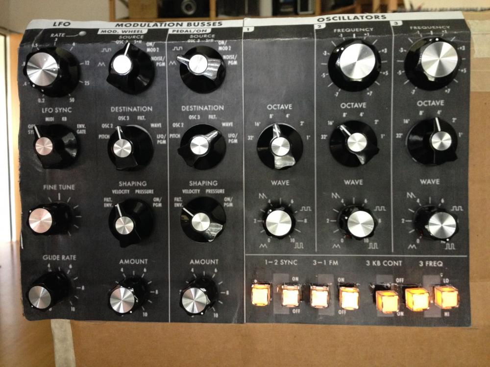
@FantomXR: It's a print screen out of the Moog Voyager Synth PDF manual. Horrible resolution, but a start to get the front panel together :-) I am currently redesigning the layout in inkscape which is a freakin pain in the butt since lines get misaligned frequently and I didn't manage to get nice concentric scales around the buttons (the nice plugin for exactly that which I found online doesn't work with my installation).
I'm still not happy about the fact, that the config always works fine after a reboot for a couple of button presses. Any other idea how to nail this?
Cheers
Andy
-
Hey Thorsten
Thanks for the update. Unfortunately, the init seems not to be working properly every time. Where as module 2 is working every time with v1.032, now I either have 4 or only 1 module working. Rebooting always only enables 1 module no matter how many times I try. Only if I reflash the software several times, suddenly all modules work after about 5 to 8 tries.
Update: Soft resetting via MIOS terminal sometimes also helps after a couple of tries.
Best Regards, Andy
-
Hey fellow midiboxers
I start feeling bad, always coming with more problems instead of solutions. But another unsolved mystery in my Midibox_NG project (next to operating more than 2 AOUT_NGs) is an odd behavior of my DIO Matrix.
Basically, it is configured like in the example for 8x16 buttons and 8x8 LEDs. In my configuration, I have a couple of rotary switches configured as OnOnly for the different states as wells as some toggle buttons with included LEDs:
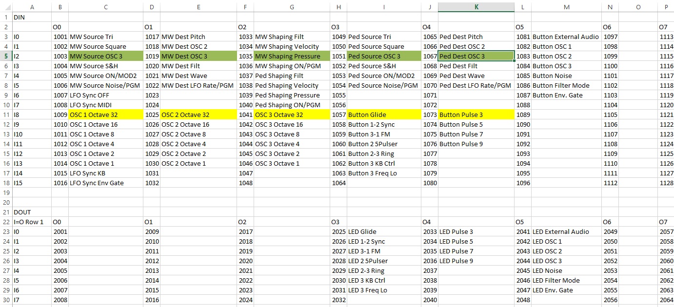
the matrix is wired as follows:
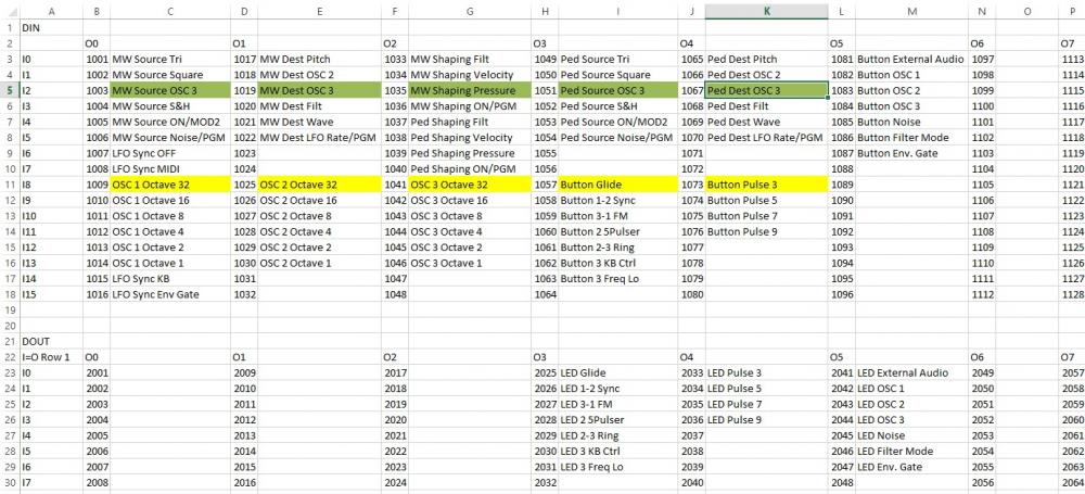
and this is how the configuration looks like:
# DIN_MATRIX hardware
DIN_MATRIX n=1 rows=8 sr_dout_sel1=1 sr_din1=1 sr_din2=2 button_emu_id_offset=1001# DOUT_MATRIX hardware
DOUT_MATRIX n=1 rows=8 sr_dout_sel1=1 sr_dout_r1=2 led_emu_id_offset=2001# EVENTs #MOD BUS EVENT_BUTTON id= 1001 type=CC button_mode=OnOnly chn= 1 CC= 68 range= 0:0 lcd_pos=1:1:4 label="MW Source Tri " EVENT_BUTTON id= 1002 type=CC button_mode=OnOnly chn= 1 CC= 68 range= 25:25 lcd_pos=1:1:4 label="MW Source Square " EVENT_BUTTON id= 1003 type=CC button_mode=OnOnly chn= 1 CC= 68 range= 51:51 lcd_pos=1:1:4 label="MW Source OSC 3 " EVENT_BUTTON id= 1004 type=CC button_mode=OnOnly chn= 1 CC= 68 range= 76:76 lcd_pos=1:1:4 label="MW Source S&H " EVENT_BUTTON id= 1005 type=CC button_mode=OnOnly chn= 1 CC= 68 range= 102:102 lcd_pos=1:1:4 label="MW Source ON/MOD2 " EVENT_BUTTON id= 1006 type=CC button_mode=OnOnly chn= 1 CC= 68 range= 127:127 lcd_pos=1:1:4 label="MW Source Noise/PGM " EVENT_BUTTON id= 1017 type=CC button_mode=OnOnly chn= 1 CC= 69 range= 0:0 lcd_pos=1:1:4 label="MW Dest Pitch " EVENT_BUTTON id= 1018 type=CC button_mode=OnOnly chn= 1 CC= 69 range= 25:25 lcd_pos=1:1:4 label="MW Dest OSC 2 " EVENT_BUTTON id= 1019 type=CC button_mode=OnOnly chn= 1 CC= 69 range= 51:51 lcd_pos=1:1:4 label="MW Dest OSC 3 " EVENT_BUTTON id= 1020 type=CC button_mode=OnOnly chn= 1 CC= 69 range= 76:76 lcd_pos=1:1:4 label="MW Dest Filt " EVENT_BUTTON id= 1021 type=CC button_mode=OnOnly chn= 1 CC= 69 range= 102:102 lcd_pos=1:1:4 label="MW Dest Wave " EVENT_BUTTON id= 1022 type=CC button_mode=OnOnly chn= 1 CC= 69 range= 127:127 lcd_pos=1:1:4 label="MW Dest LFO Rate/PGM" EVENT_BUTTON id= 1033 type=CC button_mode=OnOnly chn= 1 CC= 70 range= 0:0 lcd_pos=1:1:4 label="MW Shaping Filt " EVENT_BUTTON id= 1034 type=CC button_mode=OnOnly chn= 1 CC= 70 range= 48:48 lcd_pos=1:1:4 label="MW Shaping Velocity " EVENT_BUTTON id= 1035 type=CC button_mode=OnOnly chn= 1 CC= 70 range= 80:80 lcd_pos=1:1:4 label="MW Shaping Pressure " EVENT_BUTTON id= 1036 type=CC button_mode=OnOnly chn= 1 CC= 70 range= 127:127 lcd_pos=1:1:4 label="MW Shaping ON/PGM " EVENT_BUTTON id= 1037 type=CC button_mode=OnOnly chn= 1 CC= 73 range= 0:0 lcd_pos=1:1:4 label="Ped Shaping Filt " EVENT_BUTTON id= 1038 type=CC button_mode=OnOnly chn= 1 CC= 73 range= 48:48 lcd_pos=1:1:4 label="Ped Shaping Velocity" EVENT_BUTTON id= 1039 type=CC button_mode=OnOnly chn= 1 CC= 73 range= 80:80 lcd_pos=1:1:4 label="Ped Shaping Pressure" EVENT_BUTTON id= 1040 type=CC button_mode=OnOnly chn= 1 CC= 73 range= 127:127 lcd_pos=1:1:4 label="Ped Shaping ON/PGM " EVENT_BUTTON id= 1049 type=CC button_mode=OnOnly chn= 1 CC= 71 range= 0:0 lcd_pos=1:1:4 label="Ped Source Tri " EVENT_BUTTON id= 1050 type=CC button_mode=OnOnly chn= 1 CC= 71 range= 25:25 lcd_pos=1:1:4 label="Ped Source Square " EVENT_BUTTON id= 1051 type=CC button_mode=OnOnly chn= 1 CC= 71 range= 51:51 lcd_pos=1:1:4 label="Ped Source OSC 3 " EVENT_BUTTON id= 1052 type=CC button_mode=OnOnly chn= 1 CC= 71 range= 76:76 lcd_pos=1:1:4 label="Ped Source S&H " EVENT_BUTTON id= 1053 type=CC button_mode=OnOnly chn= 1 CC= 71 range= 102:102 lcd_pos=1:1:4 label="Ped Source ON/MOD2 " EVENT_BUTTON id= 1054 type=CC button_mode=OnOnly chn= 1 CC= 71 range= 127:127 lcd_pos=1:1:4 label="Ped Source Noise/PGM" EVENT_BUTTON id= 1065 type=CC button_mode=OnOnly chn= 1 CC= 72 range= 0:0 lcd_pos=1:1:4 label="Ped Dest Pitch " EVENT_BUTTON id= 1066 type=CC button_mode=OnOnly chn= 1 CC= 72 range= 25:25 lcd_pos=1:1:4 label="Ped Dest OSC 2 " EVENT_BUTTON id= 1067 type=CC button_mode=OnOnly chn= 1 CC= 72 range= 51:51 lcd_pos=1:1:4 label="Ped Dest OSC 3 " EVENT_BUTTON id= 1068 type=CC button_mode=OnOnly chn= 1 CC= 72 range= 76:76 lcd_pos=1:1:4 label="Ped Dest Filt " EVENT_BUTTON id= 1069 type=CC button_mode=OnOnly chn= 1 CC= 72 range= 102:102 lcd_pos=1:1:4 label="Ped Dest Wave " EVENT_BUTTON id= 1070 type=CC button_mode=OnOnly chn= 1 CC= 72 range= 127:127 lcd_pos=1:1:4 label="Ped Dest LFO Rate/PGM" #OSC EVENT_BUTTON id= 1009 type=CC button_mode=OnOnly chn= 1 CC= 74 range= 64:64 fwd_id=SENDER:3001 lcd_pos=1:1:4 label="OSC 1 Octave 32 " EVENT_BUTTON id= 1010 type=CC button_mode=OnOnly chn= 1 CC= 74 range= 65:65 fwd_id=SENDER:3001 lcd_pos=1:1:4 label="OSC 1 Octave 16 " EVENT_BUTTON id= 1011 type=CC button_mode=OnOnly chn= 1 CC= 74 range= 66:66 fwd_id=SENDER:3001 lcd_pos=1:1:4 label="OSC 1 Octave 8 " EVENT_BUTTON id= 1012 type=CC button_mode=OnOnly chn= 1 CC= 74 range= 67:67 fwd_id=SENDER:3001 lcd_pos=1:1:4 label="OSC 1 Octave 4 " EVENT_BUTTON id= 1013 type=CC button_mode=OnOnly chn= 1 CC= 74 range= 68:68 fwd_id=SENDER:3001 lcd_pos=1:1:4 label="OSC 1 Octave 2 " EVENT_BUTTON id= 1014 type=CC button_mode=OnOnly chn= 1 CC= 74 range= 69:69 fwd_id=SENDER:3001 lcd_pos=1:1:4 label="OSC 1 Octave 1 " EVENT_BUTTON id= 1025 type=CC button_mode=OnOnly chn= 1 CC= 75 range= 64:64 fwd_id=SENDER:3002 lcd_pos=1:1:4 label="OSC 2 Octave 32 " EVENT_BUTTON id= 1026 type=CC button_mode=OnOnly chn= 1 CC= 75 range= 65:65 fwd_id=SENDER:3002 lcd_pos=1:1:4 label="OSC 2 Octave 16 " EVENT_BUTTON id= 1027 type=CC button_mode=OnOnly chn= 1 CC= 75 range= 66:66 fwd_id=SENDER:3002 lcd_pos=1:1:4 label="OSC 2 Octave 8 " EVENT_BUTTON id= 1028 type=CC button_mode=OnOnly chn= 1 CC= 75 range= 67:67 fwd_id=SENDER:3002 lcd_pos=1:1:4 label="OSC 2 Octave 4 " EVENT_BUTTON id= 1029 type=CC button_mode=OnOnly chn= 1 CC= 75 range= 68:68 fwd_id=SENDER:3002 lcd_pos=1:1:4 label="OSC 2 Octave 2 " EVENT_BUTTON id= 1030 type=CC button_mode=OnOnly chn= 1 CC= 75 range= 69:69 fwd_id=SENDER:3002 lcd_pos=1:1:4 label="OSC 2 Octave 1 " EVENT_BUTTON id= 1041 type=CC button_mode=OnOnly chn= 1 CC= 76 range= 64:64 fwd_id=SENDER:3003 lcd_pos=1:1:4 label="OSC 3 Octave 32 " EVENT_BUTTON id= 1042 type=CC button_mode=OnOnly chn= 1 CC= 76 range= 65:65 fwd_id=SENDER:3003 lcd_pos=1:1:4 label="OSC 3 Octave 16 " EVENT_BUTTON id= 1043 type=CC button_mode=OnOnly chn= 1 CC= 76 range= 66:66 fwd_id=SENDER:3003 lcd_pos=1:1:4 label="OSC 3 Octave 8 " EVENT_BUTTON id= 1044 type=CC button_mode=OnOnly chn= 1 CC= 76 range= 67:67 fwd_id=SENDER:3003 lcd_pos=1:1:4 label="OSC 3 Octave 4 " EVENT_BUTTON id= 1045 type=CC button_mode=OnOnly chn= 1 CC= 76 range= 68:68 fwd_id=SENDER:3003 lcd_pos=1:1:4 label="OSC 3 Octave 2 " EVENT_BUTTON id= 1046 type=CC button_mode=OnOnly chn= 1 CC= 76 range= 69:69 fwd_id=SENDER:3003 lcd_pos=1:1:4 label="OSC 3 Octave 1 " #LFO EVENT_BUTTON id= 1007 type=CC button_mode=OnOnly chn= 1 CC= 67 range= 0:0 lcd_pos=1:1:4 label="LFO Sync OFF " EVENT_BUTTON id= 1008 type=CC button_mode=OnOnly chn= 1 CC= 67 range= 48:48 lcd_pos=1:1:4 label="LFO Sync MIDI " EVENT_BUTTON id= 1015 type=CC button_mode=OnOnly chn= 1 CC= 67 range= 80:80 lcd_pos=1:1:4 label="LFO Sync KB " EVENT_BUTTON id= 1016 type=CC button_mode=OnOnly chn= 1 CC= 67 range= 127:127 lcd_pos=1:1:4 label="LFO Sync Env Gate " EVENT_BUTTON id= 1057 type=CC fwd_id=LED:2025 button_mode=Toggle chn= 1 cc= 65 range= 0:127 lcd_pos=1:1:4 label="Glide ^onoff " EVENT_BUTTON id= 1058 type=CC fwd_id=LED:2026 button_mode=Toggle chn= 1 cc= 77 range= 0:127 lcd_pos=1:1:4 label="1-2 Sync ^onoff " EVENT_BUTTON id= 1059 type=CC fwd_id=LED:2027 button_mode=Toggle chn= 1 cc= 78 range= 0:127 lcd_pos=1:1:4 label="3-1 FM ^onoff " EVENT_BUTTON id= 1060 type=CC fwd_id=LED:2028 button_mode=Toggle chn= 1 cc= 90 range= 0:127 lcd_pos=1:1:4 label="5Pulser ^onoff " EVENT_BUTTON id= 1061 type=CC fwd_id=LED:2029 button_mode=Toggle chn= 1 cc= 95 range= 0:127 lcd_pos=1:1:4 label="2-3 Ring ^onoff " EVENT_BUTTON id= 1062 type=CC fwd_id=LED:2030 button_mode=Toggle chn= 1 cc= 79 range= 0:127 lcd_pos=1:1:4 label="3 KB Cont ^onoff " EVENT_BUTTON id= 1063 type=CC fwd_id=LED:2031 button_mode=Toggle chn= 1 cc= 80 range= 0:127 lcd_pos=1:1:4 label="3 Freq ^highlow " EVENT_BUTTON id= 1073 type=CC fwd_id=LED:2033 button_mode=Toggle chn= 1 cc= 91 range= 0:127 lcd_pos=1:1:4 label="Pulse 3 ^onoff " EVENT_BUTTON id= 1074 type=CC fwd_id=LED:2034 button_mode=Toggle chn= 1 cc= 92 range= 0:127 lcd_pos=1:1:4 label="Pulse 5 ^onoff " EVENT_BUTTON id= 1075 type=CC fwd_id=LED:2035 button_mode=Toggle chn= 1 cc= 93 range= 0:127 lcd_pos=1:1:4 label="Pulse 7 ^onoff " EVENT_BUTTON id= 1076 type=CC fwd_id=LED:2036 button_mode=Toggle chn= 1 cc= 94 range= 0:127 lcd_pos=1:1:4 label="Pulse 9 ^onoff " EVENT_BUTTON id= 1081 type=CC fwd_id=LED:2041 button_mode=Toggle chn= 1 cc= 81 range= 0:127 lcd_pos=1:1:4 label="External Audio ^onoff " EVENT_BUTTON id= 1082 type=CC fwd_id=LED:2042 button_mode=Toggle chn= 1 cc= 82 range= 0:127 lcd_pos=1:1:4 label="OSC 1 ^onoff " EVENT_BUTTON id= 1083 type=CC fwd_id=LED:2043 button_mode=Toggle chn= 1 cc= 83 range= 0:127 lcd_pos=1:1:4 label="OSC 2 ^onoff " EVENT_BUTTON id= 1084 type=CC fwd_id=LED:2044 button_mode=Toggle chn= 1 cc= 84 range= 0:127 lcd_pos=1:1:4 label="OSC 3 ^onoff " EVENT_BUTTON id= 1085 type=CC fwd_id=LED:2045 button_mode=Toggle chn= 1 cc= 85 range= 0:127 lcd_pos=1:1:4 label="Noise ^onoff " EVENT_BUTTON id= 1086 type=CC fwd_id=LED:2046 button_mode=Toggle chn= 1 cc= 86 range= 0:127 lcd_pos=1:1:4 label="Filter Mode ^filmode " EVENT_BUTTON id= 1087 type=CC fwd_id=LED:2047 button_mode=Toggle chn= 1 cc= 87 range= 0:127 lcd_pos=1:1:4 label="Env Gate ^envgate "
If I reboot the midibox, all buttons and LEDs work as intended. But after a couple of button presses, suddenly two strange things happen:
- Rotary switches start to lock each other out. If one switch is in position green on the matrix table, the same position in terms of DIN row of other switches is not registered any longer.
- Switches trigger all button events in the same row (e.g. the ones marked yellow in the matrix table). One small detail is that if this happens, the LEDs of the corresponding buttons are getting brighter, the more switches of this row are in the actual ON position. For example, if ID 1009 suddenly starts to trigger ID1025. 1041, 1057 and 1073, LED 2025 and 2033 switch on. If the second rotary switch is set to the position wit the ID1025, the LEDs 2025 and 2033 get brighter. If I toggle on button 1057 (pressing and releasing it), both LEDs 2025 and 2033 even get brighter. In reverse, if I toggle buttons off, the LEDs get dimmer again. You can actually see differently bright lit LEDs in the picture I took of the front panel mockup.
Now what could the actual problem behind this behavior be? What is strange is, that everything always works after rebooting and suddenly starts, after I pressed a couple of buttons or did a couple of switches. Can it be some capacitive behavior of the ribbon cables I used to connect the switches (some are up to 40cm long) which builds up over time? Or could it have something to do with the fact that the rotary switches trigger one of the 4 to 8 switches in every scan (some kind of stack overflow)? What do you think I could try to get closer to a solution?
I appreciate your thoughts and hints regarding this behavior.
Best regards and a happy weekend
Andy
-
Do you have enough AOUT_NGs laying around for the tests or can I help you with anything by performing tests?
I did a couple of tests myself:
- exchanged all cables and modules with each other. Still the third module does nothing and the other two work.
- fed 5V directly to the third module to rule out voltage drop
- reduced cable length by eliminating the AINSER_64 which is daysichained ahead of the AOUT_NG modules.
- configured 16 channels in the hope that module 3 would replicate module 1. No change with or without the AINSER_64 (however,I don't fully understand the transfer protocol, so maybe if the software only feeds 2 modules, the third won't do anything no matter what)
- measured DOUT of the third module and didn't measure any signal coming out
One thing I noticed though is, that if I fully sweep the output CV of a channel of the third module, the voltage changes from 0.09 to 0.11 V.
This does not make any sense to me, but maybe it could be a clue what's going on here.
Thanks for your effort!
Regards,
Andy
-
Hmmm, has anybody been successful with more than 2 AOUT_NG Modules? I am struggling with the 3rd module which does not respond yet (checked cabling and also if this additional module is actually working, which it is). So, no luck with more than 16 channels yet.
I set
AOUT type=AOUT_NG cs=1 num_channels=24 (cs=0 still used for AINSER)
and addressed the new channels with
fwd_id=CV:17
upwards
But nope, no response yet. Thanks for your reply!
Cheers,
Andy
-
Hey everybody. After some hot summerholidays it is time to work on my synth again.
Meanwhile, all the PCBs (except for the modbus/ DOUT board which still has to be designed) have arrived and are ready to be populated. [photos comming soon]
The 5Pulser and Ringmod board worked on the first try after the soldering was complete. It was still a lot of work cabling and tuning everything, but it all worked straight away which is seldom the case in my electronics experience.
I also just finished assembling, tuning and debugging the filter stage. This was a lot more work as the circuits are a lot more complex and have to work unisono. It is now possible to switch between using the two LP filters in parallel to generate a Stereo effect by phase shifting one filter or using one LP filter sequentially with the HP filter generating a bandpass and also phase shifting the HP filter to widen the band.
By using, switching and shifting I mean doing it manually, since these modules are not yet connected to the midibox controller. The analog part should be easy, as I configured everything already when I did the VCO stages. However, I haven't tackled DOUT to switch relays as well as toggle LED buttons on the DIO MATRIX side yet. And since I haven't done a lot of midibox programming/ configuration work lately, it will be a challenge again to get everythong hoocked up properly.
Next will be the ADSR and VCA circuits. The boards are populated and ready for testing.
-
Ok, thanks a lot for your quick reply. Let me know if you consider such an option. It Would be great to be able to midi sync my Synth.
Cheers,
Andy
-
Hey everybody
I searched in the forum as well as the NG documentation but couldn't find anything about this topic. Is there a possibility to forward the midi clock pulse or a division of it to a DOUT pin (comming either from the internal generator or an external clock through midi in)? I would like to sync an LFO to the clock.
Cheers
Andy
-
Too bad. Although, I would not care if I needed to design another scan circuit. But as long as the midibox_NG cannot scan "Charlieplexed" (good to know what the "official" name is) matrices, it wouldn't work anyway.
If you are interested in the RBG price, I can pm you the contact of the salesperson.
-
Has anybody built a BLM with bidirectional two lead duocolor LEDs, where the two colors can be adressed by reversing the polarity?

How would the scan circuit have to be designed in order to work with the standard midibox solutions? Of course, compared with the scalar board, the resistor-transistor arrangement of IC2 could be placed next to IC3 and another 74HC595 next to IC2. But then the scan algorythm would also have to scan each color sequentially.
Why am I looking for such a solution? I evaluated the the switch of choice for my Synth project:

For my needs, I only have single color buttons (yellow). But this button could also be interesting for BLM applications where duocolor would be needed (RGB is available as well).
I am working on a versatile matrix PCB solution for my synth project, where single rows of a matrix can be cut to the desired length and the LEDs can be adressed individually via solder jumpers. These smaller boards can be bought much cheaper in small quantities than the propriatary matrix boards and in my case serve different needs.
-
Hey guys
I evaluated an LED backlit push button switch for my Synth project. Well Buying's TC011-A S4 T turned out to be the perfect switch for my needs:

Although called tact switch, it feels more like a push button switch with a smooth pressure point and doesn't have the distinct click of a membrane switch. It's more like a Marquart but with a stronger spring resistance and a more defined switching point. The cap is 11x11 mm, translucent with a white diffusor cap inside (other versions with only square white caps are also available), as well as an ergonomic indent. There are different color options as well as duocolor and RGB available. Unfortunately, the duocolor version (colors can be chosen freely, as far as I know) is a bidirectional setup, where the LED has to be adressed by switching the polarity of the two leads.
The switches can be obtained relatively cheap directly from the manufacturer Wellbuying from China. For a lot of 100 pcs, I paid only USD 0.78 a piece for a single color version.
If anybody is interested, I can post pictures of the yellow as well as the orange version in action. I also have a contact, if somebody needs switches. Meanwhile, they are also available through Mouser, but for a much higher price.
Find an individually addressable four button PCB eagle schematic for single LED type TC011s including the part library:
Important: In case you want to use these PCBs in conjunction with a Schaeffer frontpanel with standoffs (no through hole), the mounting holes on the PCB need to be further apart as the glued on standoffs have quite a large base which otherwise interfer with the routed holes for the buttons.
-
After a longer pause, the project is moving on. Find the documentation and schematics of my VCO, waveshaper & VCM design here:
https://www.muffwiggler.com/forum/viewtopic.php?p=1856429#1856429
The PCBs of the LP part of my VCF are ordered and the HP portion is in design.
-
Perfect, you are welcome!
-
Hi Markus
How long is your cable between the LPC17 and the AOUT_NG? I had some trouble in the beginning, when I had a cable which was longer than 10-20cm.
I don't see any reason, why you should have damaged the chip with the wrong connection you mentioned. As long as you don't connect these pins to +/-12V, you should be save.
cheers
Andy
-
Did you really experiance audible distortion when AC coupling the signal? Should be very doable with a low enough Lowcut around 5Hz. Eg 330nf into a 100k load.
Using a sineshaper is in fact nice as you can morph from tri to sine to square, or from saw to rounded saw to pulse.
I found this sounds even more useful compared to the tri to saw fading as it provides a nice range of morphing overtones, really altering the spectrum (compared to just fading in the upper overtones with a tri to saw fade.
Of course the fading from tri to saw is nice as well! What would be cool: real morphing of the up and down portion of the ramps at a given frequency. Seems like this is rather a complex task in an analog circuit though... Some digital synths do it, sounds very nice.
To be honest, I never checked how much distortion an additional AC coupling would cause. I went for the classic 10k, 10uF and noticed that the sharp edges of the sawtooth and traingle get rounded a bit on the scope. That's when I decided not to do any more AC coupling on the VCO.
You're right, real morphing would be very nice. However, controlling the upper and lower portion gets more complex and as you say, is also a bit more complex to realise with analog circuits. Ian Fritz has two nice approaches with the "Wavolver" and the "SNICster": http://home.comcast.net/~ijfritz/sy_over.htm
Hmm, you also don't have any idea what I could try to solve the DIO_matrix rotary switch problem?
-
Thanks a lot for your insights in your project!
As it seems, I took a very similar approach to your solution.
- I actually do exactly the same, voltage controlling a common saw to tri converter to do this kind of transition. And that's where I had the first problem, compensating the voltage level from cutting the saw signal to half and also balancing it around 0V. I solved this with the first LM13700 only being affected during saw-tri transition.
- However, I didn't AC couple the signal between tri-saw and saw-rect to keep the distortion as low as possible. As a result, the signal at the output before the AC coupling moves from -10/0 to 0/+10, limiting the different trimming ranges due to the DC component of the signal.
- I wanted to use only one CV to blend through all the different wave shapes. Therefore I split the CV, using the lower half (0-5V) for the tri-saw transition and the upper half (5-10V) to transit from saw to rect as well as subsequently modulate the pulse width of the rectangle. The pulse width modulation is only done with the rectangle and not with the triangle signal.
- Your solution with the sine converter to get a rectangle sounds pretty neat. I copied the circuit used in the micromoog, which uses a variable threshold to clamp the signal to a positive DC level above the triangle AC signal level. This leads to an instant doubling of the pp voltage. It's not that critical for the signal volume however, since the average volume does not change that much.
- The LDR approach is probably very precise, since the average signal volume changes a lot during transition. I managed to get pretty much the same pp values for the three clean mayor signals saw, tri and rect. Of course, the over all volume changes during the tri-rect transition and again during rect PWM. But I'm still happy with the result.
By the way, the documentation on the muffwiggler forum is not yet finished. Meanwhile, I have the circuit refined, the PCB edged three times and all three VCO's are working very well together after a lot of tweaking the circuits. I am going to document the final circuit as well as all the findings soon.
-
Strange DIO_MATRIX rotary switch problem:
On the front panel, I use 9 rotary switches to select stuff like octave, modulation routing, etc. The cabling is done like the typical scan matrix application for DIO_matrix modules (http://www.ucapps.de/midio128/midio128_v3_dio_scanmatrix.pdf). I connected the multiple switch positions of my first rotary switch to C0-C7 and the slider via a diode to R0. The second switch is connected to C0-C7 and R1, and so on, and so forth. Unlike momentary switches, one position of each rotary switch is always ON, of course.
When I switch on the midibox initially, usually I am able to select each position on each switch as desired. But somehow, after a while/a couple of times switching/operating several different switches/many switches in the same position (not sure yet, what causes the new behavior), I can suddenly not select the same position as a certain other switch has anymore.
E.g. switch A is in position 2 and I operate switch B. The LCD display shows each change of switch B reliably. But suddenly, when I try to put switch B to position 2 (again), the display shows, that I have put switch A to position 2 instead. I am then not able to put switch B to position 2 anymore, until I change switch A to position 3 for example. But now, position 3 of switch B is locked until I change the position of switch A again.
Does anybody have an idea, what could cause this interlocking situation? As I don't know, how the DIO_matrix's scanning pattern works, it is hard for me to figure out what could cause this behavior. I can only guess that it could be a problem related to:
- cable length leading to some kind of interference problem (I have one 20 cm flat ribbon cable from the module to a distribution node and lengths from there to the switches between 10-30 cm)
- some kind of saturation problem (because it is occurring over time)
- depending on the scan pattern, too many switches in the same position causing unwanted voltage drops
I might be able to shorten the cable from the module to the node a little bit, but that won't help on the maximum length that much. Another thing to try would be to completely reverse how the rotary switches are connected and go from C0 via diode to the slider and connect the different positions to R0-R7.
Before I start messing up the nice cabling and spend another 5 m of new cables and hours of my time, I would like to hear your opinion on this. Has anybody experienced similar problems?
-
After over a year of development, I would like to start documenting my Midibox_NG project in this thread to collect as much information as possible for similar future projects. The idea is to keep all findings, questions and struggles concerning this projects in one thread to keep myself organised and to help future digital/analog synth developers.
As the title predicts, the goal of this project is to design and develop an all in one box digitised analog synth, similar to the MiniMoog Voyager. The synth will be controlled solely over midi. An LPC17 with Midibox_NG running acts as the main brain to read digital pots and switches of the control panel, save and recall presets as well as to drive the synth through multiple analog and digital outputs.
Analog synth hardware:
1x LFO
2x Modulation Bus
3x VCO incl. waveshapers as well as additional loops for other effects than the waveshapers (documented on: http://www.muffwiggler.com/forum/viewtopic.php?t=108794)
1x Noise generator
1x Ext_In
1x Mixer stage
1x 5Pulser (http://home.comcast.net/~ijfritz/sy_cir8.htm)
1x Ring modulator
1x Phaser effect
2x Moog ladder LP filter (to create a stereo effect through filter cutoff spacing)
1x Moog T904B HP filter (to create a band pass together with one of the LP filters (http://www.freeinfosociety.com/electronics/schemview.php?id=944)
2x ADSR (for filter and volume)
1x Stereo VCA
1x Headphone preamp
1x +/-15V & +5V switching power supply (I learned, that it is much easier to develop circuits with the additional "headroom" of +/-3V in comparison to a +/-12V supply)
1x Power board to generate +/-12V for the AOUT_NG modules as well as +10V clean reference voltage.Resources
All the analog circuits are redesigned and relayouted to be uC controllable. They are mainly based on the following modules:
- Ninni Bergfors' Moog based bergfotron modules (http://hem.bredband.net/bersyn/)
- Original Moog D schematics (http://www.fantasyjackpalance.com/fjp/sound/synth/synthdata/16-moog-minimoog.html)
- Original Micromoog schematics (http://www.fantasyjackpalance.com/fjp/sound/synth/synthdata/07-moog-micromoog.html)- Yves Usson's Yusynth (http://yusynth.net/Modular/index_en.html)
- René Schmitz's modules (http://www.schmitzbits.de/)
- Carsten Toensmann's Moog Modular Clone (http://www.analog-monster.de/mmschemos.html)- Vinnui's Modbus concept (http://vinnui.blogspot.ch/2011/09/concept-of-modulation-bus.html)
The original idea was to use the Moog D schematics solely and as many original parts as possible. But after already acquiring many old parts for a reasonable amount of money, I dumped the idea when the last Chinese seller of UA726 remakes went off market. However, I don't regret the decision, as I am very happy with my results so far with more modern parts, which are not nearly as energy hungry as the old stuff.
Midibox Hardware:
1x LPC17 core module
1x KS0108 based graphic LCD
1x SD card reader
1x AINSER64 module
1x DIO_MATRIX module
1x DOUT module (own design with partly high power shift registers for switching relays)
4x AOUT_NG modules
Development Roadmap (fully implemented, partly done, not touched yet):
- HARDWARE Power Board
- HARDWARE Midibox modules (excl. DOUT)
- HARDWARE VCO & waveshaper board (incl. trimming & tuning)
- HARDWARE LP filter
- HARDWARE HP filter & filter switching circuit
- HARDWARE 5Pulser
- HARDWARE Ring Modulator (on the breadboard and PCB layouted)
- HARDWARE ADSR (PCB layouted)
- HARDWARE DOUT module
- HARDWARE control panel pots & switches
- HARDWARE Mixer including overdrive LED circuit
- HARDWARE VCA & headphone preamp
- HARDWARE LFO, MOD BUS, Noise generator circuits and PCB
- HARDWARE Casing
- HARDWARE Phaser (planned as a seperate module, since not enough AOUTS available)- SOFTWARE Utilising AINSER64 and AOUT_NG at one port ()
- SOFTWARE Controlling multiple AOUT_NG modules at once ()
- SOFTWARE VCO octave switch option (thanks TK)
- SOFTWARE Multiple rotary switches locking each other out (softwarebug ironed out, thanks again, TK)
- SOFTWARE Controlling Digital switching ICs (binary input) by DOUTs (signal switching related topic)
- SOFTWARE synth fine tuningrange (+/- 3 semitones, steps as fine as possible) -> solved in the analog section, without midibox assistance- SOFTWARE VCO detuning -> semitone detuning works, free detuning not implemented in MBNG)
- SOFTWARE Midibox_NG menu structure -> initial work done
- SOFTWARE Preset save and recall
- SOFTWARE Midi control of parameters (excl. tone & pitch bend) -
Dear TK, god of the Midi Box :queen:
Finally I managed to finish all my three VCO boards, hooked them up to the uP and tuned the oscillators. The result with your transpose options are great and the whole note pitch as well as octave and semitone transpose only need 4 AOUTs for 3 VCOs. However, is there a possibility to have a finer resolution than semitones to transpose, (like for example pitch-bend) which I can use likewise mutliple times to detune OSC2 and 3 individually as well as finetune the whole synth to other instruments? I tried to use semitone transpose but with NRPNs instead of CCs. But the result is still a semitone transpose.
Thank you very much for these awesome features!
-
All right...I'll give you some feedback as soon as 4 AOUT_NGs are working :yes:
... btw. octave transpose is working perfectly! Semitone transpose works with CCs. Next will be a test with NRPN to see, if I get a smooth semitone transpose over a 15 semitone range without audible steps.
@lukas412: THX!
-
Sorry, everything working smoothly now. Haven't got a clue yet what the problem was, but consider it as resolved.
@Admin: Please delete this topic, thank you!

DIO Matrix going haywire
in MIDIbox NG
Posted
Alright, a little step closer:
J6 is set correctly, the pull-up resistors are the right value and solidly solderd and I also checked J27 which is fine as well (also the signal itself, not just the jumper).
But what I figured out is, that if I feed both 5V and GND directly from the PSU to the board, the fault happens much less (which means it does happen but much later). Also the noise level on the 5V rail lowers from +/-400mW to +/-60mV. But still, it does happen far too often. Also, if I connect my scope to the rail at the board, it happens more often. I soldered some 100uF cap and a 1000p cap to the board which unfortunately did not help at all. But it even gets more mysterious. If I turn AINSER64 pots, I can provoke the fault as well, which never happened before. Of course, the wires of these pots cross the button wires at some point, which won't be possible to avoid.
Well, I am a bit lost here with this mystery.