cmos
-
Posts
2 -
Joined
-
Last visited
cmos's Achievements
MIDIbox Newbie (1/4)
0
Reputation
-
541 = 74HCT541, an octal buffer/line driver. There's one in your core board (IC1) already, so you might be able to use it if you have a spare DOUT SR, otherwise check out this doc for connecting the extra bits to J28: http://ucapps.de/mbhp/mbhp_core_lpc17_output_buffers.pdf. That's from the Download/Additional info section of the core_LPC17 docs http://ucapps.de/mbhp_core_lpc17.html
-
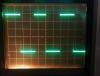
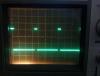
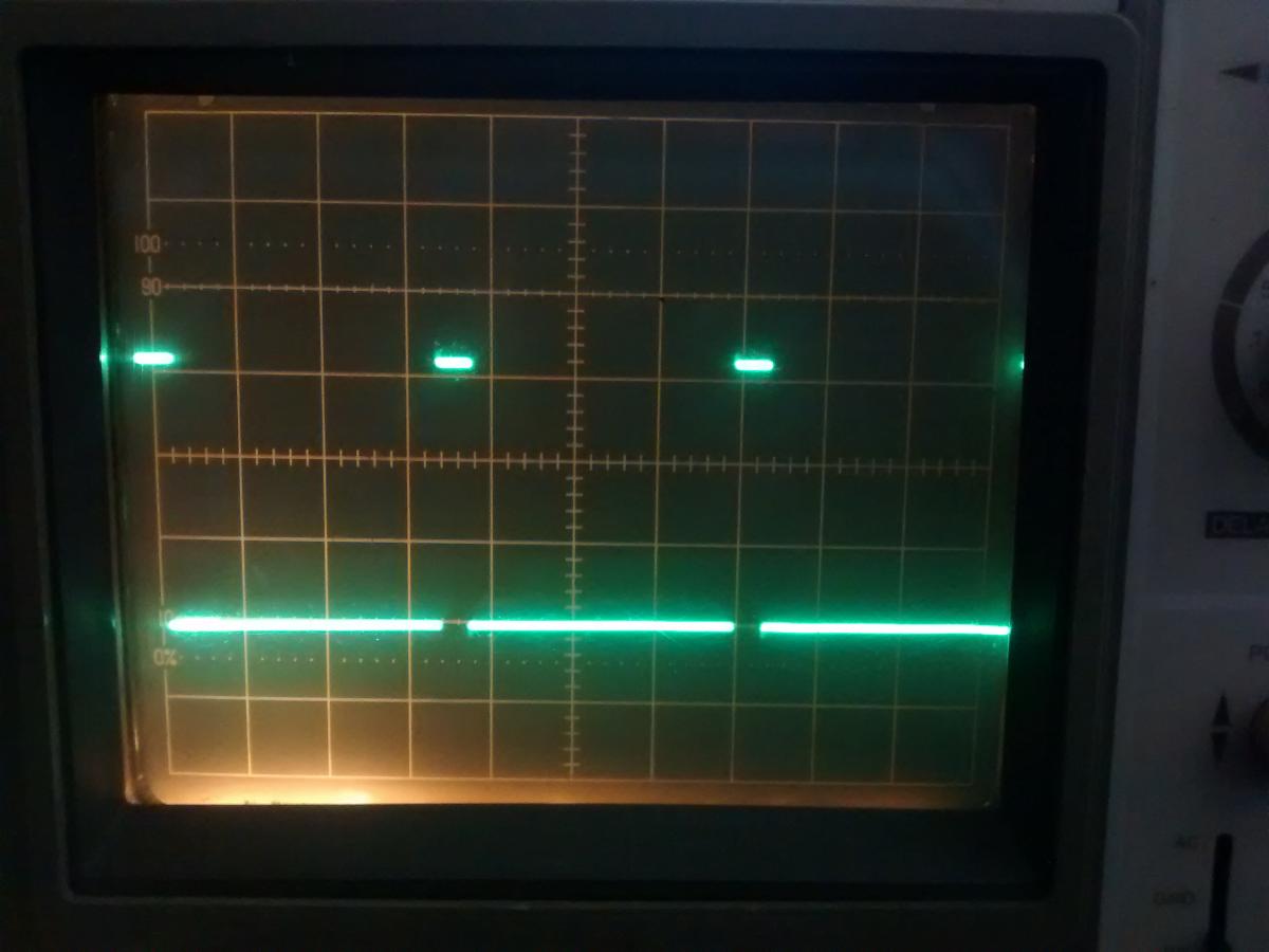
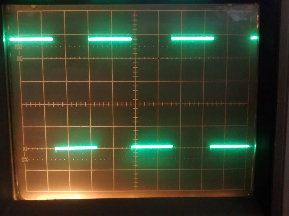
Ah the 707, the true master of many a setup and surely the greatest all round MIDI/sync/trig/converter, but with bonus drum sounds :smile: I too had timing issues with din sync24 out to a 202/303. I think I've solved it, so I thought I'd share the joy. Besides which, I've been lurking for ages, so I hope this first contribution helps other MIDIboxers. Big thanks to Mr Klose (and others) for their tireless work - we are all essentially standing on the shoulders of giants. I'm using a USB powered MBHP_CORE_LPC17 core running MIDIbox SEQ V4. I'm a long way from putting it into a case - just using bulldog clips/stripboard etc for now, though I have stuffed together 1x SD Card bodge, 2x 40x2 LCDs, 1x DIN and DOUT R5 boards, and some loose buttons to get up and running. Initially I hooked up the 303's Sync input to J28.SDA, as documented here: LPC17 connections. To my surprise, my 303 responded, i.e. it did play, although the timing was all off. There was a noticeable but inconsistent lag between some steps every bar or two, making it practically unusable. It was as if the 303 was pausing momentarily on some steps. Sort of an interesting effect, but would clearly cause any dancefloor to react badly. Initially, I thought it probably needed a 3.3V -> 5V level shift with a 541, but that didn't seem make a difference. Time to get the scope out... Here's the din sync clock output from my MC202. 5ms/dev horizontal, 1V/div vertical (though I don't trust my scope's calibration - the poor thing is nearly as old as me). Compare this with the output straight from J28.SDA. You can see it's 3.3V as expected, but the default pulsewidth (1ms?) looks too short. Stuffing this signal through a 541 and tweaking the pulsewidth, I found that 8ms was spot on with the defaults set for clock divider=16 and 24 PPQN. Now we have 5V pulses/square wave (I actually measured the supply at 4.84V with a meter on the 541) and a pic very similar to the first. More importantly, both the 202 & 303 behaved themselves as sync slaves, no longer sounding like narcoleptic amateurs. It even worked at 3.3V, without the level shifter, so it seems Roland isn't too picky about the voltage, but it's all about the pulsewidth setting - check out the CV config menu page for that. @smaudio: This seemed to happen only when my 202 was in 'play once' mode. When I saved a short pattern then went into cycle mode (shift -> cycle) the unwanted gap at the end disappeared. I see that using a dedicated DOUT for din syn clocks is now the favoured route instead of J28. I haven't checked this out yet, I'm using a SEQ V4 anyway, and this post is long enough already so I'd best leave it there. I hope the above all makes sense and the scope pics aren't too shabby. Cheers, C