-
Posts
106 -
Joined
-
Last visited
Content Type
Profiles
Forums
Blogs
Gallery
Posts posted by alchemist
-
-
Hello,
This feature is managed by acpid, used by many distributions. As said, you can better switch to Ubuntu or Debian.
-
Hello,
I guess this could be a new thread, but let's continue here ;)
I don't know how to upgrade Puppy packages, the better is to contact the Puppy maintainers.
Can't you use a more complete Linux distribution ? Puppy is quite light and it would be difficult to build something for it.
-
Hello,
The family's 6581 was dead, as was the C64 (electric shock from a desk lamp).
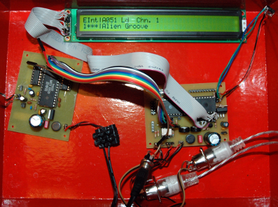
I got an other 6581 from eBay and I have a working minimal set-up:

The next step will be to build the full control surface and put all that stuff in a box (probably a C64 from a friend, so that I will have a stereo set-up)
BIG BIG THANKS to Thorsten who is so patient and answers to all my dumb questions !
-
Which version of (g)libc is installed ?
sudo ldconfig --version
There can be puppy is not using glibc but an other C library (uclibc or elibc).
In that case you will need to compile MIOS studio from sources.
-
Hello,
I've ordered an other SID 6581 on eBay, and I get sound now !
So, my family's SID was dead.
-
Yes, the sources compile fine on 32 and 64 bits, with a simple "make" call.
-
The C64 where came the SID died in beginning of years '90 (this was the family's C64). It died by electric shock from an evil desk lamp. Thus yes, it can be defective.
I will get an other C64 from a friend and test the SID on it, and test the other SID on the board.
-
Hello,
I am almost at the end : I have no sound on the MBHP_SID except a small noise like "computer sound".
I checked the connections with the interconnection app, and everything is OK (I had 3 pins not working and fixed them).
I don't see a "next check if it fails" in the walktrough... what can I do now?
I have a "plan B": since I will have a stereo setup, I will solder the second plate and test it. But plate #1 should also be fixed ;)
-
FYI: the soldering was such a mess (done with a too wide soldering tip) that I ordered an other CORE module. I've just built it this evening (with a fine soldering tip), and the MIDI I/O are now OK and really stable (I could upload the OS and applications many times).
The voltages are OK on both boards (CORE and SID).
I still have no sound, but I will check the interconnections and will connect the LCD display.
-
Hello,
I can run the binary in my 32 bits environment, but not in my 64 system, because it is true 64 bits.
And because Gentoo is source based, and because I like to compile everything I use (just useless, I know...) ;)
-
Hello,
I just created an ebuild for Gentoo Linux, that compiles the MIOS Studio sources. It's in the "pro_audio" overlay.
It as simple as "svn checkout ; unzip juce sources ; go to mios_studio linux build ; make ; copy binary" ;)
It works in 32 and 64 bits.
-
Hello,
I fixed the MIDI IN problem (short-circuits around the J10 connector). Then I uploaded the OS and the SID application. Now the display shows the boot message and SID messages :smile:
But I still have MIDI In noise, still around J10 and will fix that.
This topic is "resolved" for me.
-
Hello,
Thank you for your reply.
I did read the walkthrough manual, but I thought the SID aplication archive was the OS + the application.
I will also plug the diode, but I have now a MIDI IN problem : the upload fails, the MIDI Out sends good Sysexes, but when I do the loopback test (replace PIC by a jumper at RX/RX), the returning output is completely corrupted, and this was not so before. This was maybe due to my last checks, I did reintroduce "bugs" in the soldering... I was too enthusiastic, and did it late in the evening... not good.
But I learn a lot, and my motivation is really high :) But I have to manage the time to play with soldering with family ;)
-
OK. The 1N4148's are only for multiple CORE communications ?
-
Hello,
My SID box is almost working (MIDI I/O, voltages & ground measures on MBHP_CORE and MBHP_SID PCBs), but I have no display (just a black line) and no sound.
I tested the LCD with a 40x2 and a 16x2, both results. Both are normally compatible with the default Hitachi Driver (the 16x2 comes from my Arduino kit and working, the 40x2 is from voti.nl).
So I have 2 blocks of questions
1. LCD
- For the SID applications, I should only use 4 bit data (4-7). The SID manual don't seem to tell to use a 1k pull-up resistance on D3. Do I need to do it?
- Will the LCD display "READY" only when all is OK? or do I have to check something?
- To use the test application, do I need to do it with or without the LCD connected?
2. SID
- Do I need to remove the 6581 for the SID connection test application?
Thank you for the support!
-
Yeah !
Next step : finish the MBHP_SID board #1 and connect it to the CORE :)
-
SOLVED !
There were small short-circuits. I fixed them with a screwdriver (test CORE10).
Operating System: MIOS8
Board: MBHP_CORE or similar
Core Family: PIC18F
Bootloader is up & running!
-
Aha ! I see some other short-circuits in the MIDI out path, when it crosses a connector...
But still the same noise after the clean-up.
-
Hello,
I fixed 2 short-circuits (I had a too big soldering tip at that time) and probably 2 cold solder.
Before the fixes, it was only 0xFF, and now, it changed, but when I reply (and checked again some soldering), it's again 0xFF
I don't see always messages in the MIDI monitor, but my MIDI interfaces LEDs are always on.
With MIDIOX, I see at the moment some 0xFF's when I power off the core module.
I will recheck the components and soldering saturday. I will find it !!!
When I replug the MIDI cable, the MIDI messages change : CC's, Note On, Note Off...
Example from MIOS Studio Linux
Scanning for MIDI Inputs...
[1] Midi Through
[2] MIDIMATE II (1)
[3] MIDIMATE II (2)
MIDI Monitor ready.
[10202.628] c0 78   Chn# 1  Program Change 120
[10202.632] ff
[10203.555] e1 00 00   Chn# 2  Pitchbend -8192
[10207.340] e1 00 00   Chn# 2  Pitchbend -8192
[10211.125] e1 00 00   Chn# 2  Pitchbend -8192
[10214.910] e0 00 00   Chn# 1  Pitchbend -8192
[10218.695] e0 00 00   Chn# 1  Pitchbend -8192
[10221.845] ff
[10221.845] ff
[10221.846] ff
[10221.847] ff
[10221.849] ff
[10221.850] ff
[10221.851] ff
[10221.854] ff
[10221.854] ff
[10221.855] ff
[10222.791] e0 00 00   Chn# 1  Pitchbend -8192
[10226.576] e0 00 00   Chn# 1  Pitchbend -8192
[10230.361] e0 00 00   Chn# 1  Pitchbend -8192
[10234.146] e0 00 00   Chn# 1  Pitchbend -8192
[10237.931] e0 00 00   Chn# 1  Pitchbend -8192
[10241.716] e0 00 00   Chn# 1  Pitchbend -8192
[10245.501] e0 00 00   Chn# 1  Pitchbend -8192
[10249.286] e0 00 00   Chn# 1  Pitchbend -8192
[10253.071] e0 00 00   Chn# 1  Pitchbend -8192
[10256.856] e0 00 00   Chn# 1  Pitchbend -8192
[10260.641] e0 00 00   Chn# 1  Pitchbend -8192
[10264.426] e0 00 00   Chn# 1  Pitchbend -8192
[10268.211] e0 00 00   Chn# 1  Pitchbend -8192
[10271.996] e0 00 00   Chn# 1  Pitchbend -8192
[10275.781] e0 00 00   Chn# 1  Pitchbend -8192
[10279.566] e0 00 00   Chn# 1  Pitchbend -8192
[10283.351] e0 00 00   Chn# 1  Pitchbend -8192
[10287.136] e0 00 00   Chn# 1  Pitchbend -8192
[10290.921] e0 00 00   Chn# 1  Pitchbend -8192
[10294.706] e0 00 00   Chn# 1  Pitchbend -8192
[10298.491] e0 00 00   Chn# 1  Pitchbend -8192
[10302.276] e0 00 00   Chn# 1  Pitchbend -8192
[10306.061] e0 00 00   Chn# 1  Pitchbend -8192
[10309.849] e0 00 00   Chn# 1  Pitchbend -8192
[10313.632] e0 00 00   Chn# 1  Pitchbend -8192
[10317.417] e0 00 00   Chn# 1  Pitchbend -8192
[10321.202] e0 00 00   Chn# 1  Pitchbend -8192
-
Hello,
[EDIT: changed pin 26->25, this is a TX problem]
I checked the soldering and Vdd, ground. Everything seems OK now except on pin 25 (Tx).
I have 5 V on the PCB at the soldering of pin 25, but 0.8V on the pin 25 itself. I checked that the soldering is OK and I got continuity between the PCB and the pin.
And the MIDI out messages are still garbage (FF, control change, or note off).
The main.hex of mios_bootstrap_picstart_workaround_v1.zip cannot be uploaded (checksum error).
-
FYI: the 6N139 works perfectly to replace a 6N138
-
Thank you very much, I will check that later (now time to go to bed).
Even if it doesn't work at the first time, I am happy some parts work.
That board was quite more difficult than the Elex PCBs 25 years ago :shifty:
-
It was flashed by Mike.
I don't see +5V on TX and RX : http://www.ucapps.de/howtodebug/mbhp_core_extract_measuring_vdd.gif
-
The loopback test on the module works.
I will check the rest of the check-list, maybe there is a short-circuit of bad solder.


Bug in MIOS Studio 2.4.6 for Linux? Feature request?
in MIDIbox Tools & MIOS Studio
Posted
Hello,
Same problem for me : none of the "browse" buttons work (Gentoo Linux).