

Starspawn
-
Posts
47 -
Joined
-
Last visited
Content Type
Profiles
Forums
Blogs
Gallery
Posts posted by Starspawn
-
-
Eventual success!! After checking everything else I finally found the missing jumpers under the DOUTX4 v1 pcb ... shift registers had no ground. I blame me 6 years ago, and the fact that that is not the connections between pcbs that I doublechecked over and over.
-
Only a slight update, have been troubleshooting a bit, but just mentioning what Im completely sure of.
With the config pasted earlier, the leds on the I to IV buttons do light up sometimes, mainly just when either select or mute all is chosen by the wilba panel, the IV led either goes green or red.
So that would indicate serial is received by IC9, and it does what it is told to in the config (light up at that action).
The question then is, how do I make the buttons take the actions their leds are showing? The encoder works, so buttons should as well, but I cant see what they are called in the settings? It doesnt go through the serial chain?
And at the same time, could someone just give me a default setting where I am supposed to see Aout gates? Just setting Aout channel and getting the CV out isnt enough to get the gates at the corresponding Dout serial as well? Should it be?
-
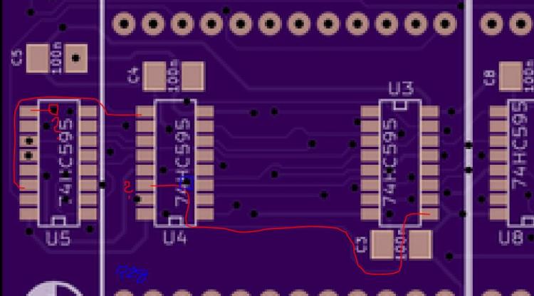
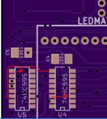
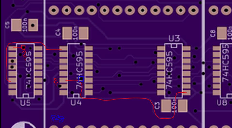
Edit: Ignore question marks.The path from U4 9 to U5 14 seems clear. The one I marked previously goes to IC end of R28 so comes from U3. I have continuity where I am supposed to have continuity. So back to settings and software.
-
Might just have been crosseyed on the first pass looking at pcb, these are the correct paths?
-
Another thing, on the schematic for the TPD the serial chain from U4 to U5 is connected from pin 9 to pin 14, however, on PCB it seems to go pin 9 to pin 9 and pin 14 to pin 14? But from U3 to U4 and and from U5 to U9 its pin 9 to pin 14 as schematic.
Could that cause a problem in the serial chain, or is there some purpose to that? -
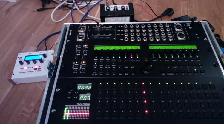
With the above configuration the behaviour of the TPD is to give me upwards counting red leds with each step count (counting all tracks at the same time on default, so full red led row upwards), and green leds lighting up towards 7th top led every time something happens on the corresponding track (so with only event on track one, just the leftmost column lights up). Can anyone confirm that this is correct, and maybe some settings to use to test it further?
-
Correct, SR17 is set to Led - Select (17 - 04) and Led - Mute all tracks (17 - 00), but as mentioned do nothing as far as I can tell, certaintly no lights except at startup.
The Doutx4 is set for SR18-20 (gates, triggers, clocks).
Im using V4+ .096 ... ehm maybe thats it? Whats the last V4 standard software?I can do fine fine soldering by hand, but Im a programming bumpkin :/
-
So my midibox is mostly happy, led issues sorted out, aout perfectly calibrated, BLM and TPD doing what they should, but the TPD has a problem I think may be setup related.
First up, the 4 buttons only light up at startup, and most importantly the Doutx4 after do nothing. So hardware wise that would indicate the serial chain not passing through somehow. Ive checked U5 and U9, the led matrix works as far as I can tell (two colours, counting up, and showing note on on channel) so the serial must pass through it, and U9 has been very carefully checked and changed for certainty, but neither leds light up, nor does Doutx4 work. It should not be a parts or soldering error, so pointing at setup/software. Wire might be a bit long internally, but it seems to stop at U9 anyhow.
Anyone encountered something similar? Is there any setting in the v4 itself I should check? For channel or main setup/options?
I first used my own HW file, then changed to beautyofdecays file as I basically stole his setup and I thought that might fix it.
His inserted below:
##################################################
# Setup File for Wilba's Frontpanel
# $Id: MBSEQ_HW.V4 2502 2017-06-10 21:15:17Z tk $
##################################################


##################################################
# MIDI Remote Keyboard Function
##################################################

# The note number which activates the remote function
# 96 = C-6 (some MIDI monitors display C-5)
# 0 disables the remote keyboard function
MIDI_REMOTE_KEY 96

# The CC number which activates the remote function
# (e.g. to control it with a footswitch)
# Allowed numbers: 1-127 for CC#1..CC#127
# 0 disables the function (default)
MIDI_REMOTE_CC 0


##################################################
# Track Selection CC
# Allows to synchronize track selections with a DAW
##################################################

# select the mode:
# 0: no CC sent on track changes
# 1: send a single CC which contains the track number as value
# 2: send CC..CC+15 depending on track number with value 127
TRACK_CC_MODE 0

# over which port should the CC be sent?
# specifiy: USB1..USB4, OUT1..OUT4, IIC1..IIC4, AOUT (haha ;-), OSC1..OSC4
TRACK_CC_PORT USB1

# over which MIDI channel should the CC be sent (1..16)?
TRACK_CC_CHANNEL 1

# which CC number should be sent (if TRACK_CC_MODE == 2: the first CC)
TRACK_CC_NUMBER 100


##################################################
# Running status optimisation
# Enabled by default, should be disabled if a MIDI
# device connected to a MIDI port doesn't fully
# comply to the MIDI specification.
# Expects two parameters: port number and 0/1 to
# disable/enable the optimisation.
##################################################

# OUT1 (MIDI1 port of MBHP_CORE_STM32 and MBHP_CORE_LPC17 module)
RS_OPTIMISATION OUT1 1

# OUT2 (MIDI2 port of MBHP_CORE_STM32 and MBHP_CORE_LPC17 module)
RS_OPTIMISATION OUT2 1

# OUT3 (MIDI3 port of MBHP_CORE_STM32 and MBHP_CORE_LPC17 module)
RS_OPTIMISATION OUT3 1

# OUT4 (MIDI4 port of MBHP_CORE_LPC17 module)
RS_OPTIMISATION OUT4 1


##################################################
# Menu Shortcuts allow a quick selection of menu pages.
# Will be displayed when the "MENU" button is pressed
# Syntax: MENU_SHORTCUT <gp-button-number> <page-name>
#
# <gp-button-number> in the range of 1..16
# <page-name>: one of these names:
#
#   - MENU         (Page Menu)
#   - FXSEL        (Fx Selection)
#   - STEPSEL      (Step Selection)
#   - TRGSEL       (Trigger Selection)
#   - PARSEL       (Param. Selection)
#   - TRACKSEL     (Track Selection)
#   - BPM_PRESETS  (BPM Presets)
#   - EDIT         (Edit)
#   - MUTE         (Mute Tracks)
#   - MUTE_PORTS   (Mute Ports)
#   - PATTERNS     (Patterns)
#   - SONG         (Song)
#   - MIXER        (Mixer)
#   - EVENTS       (Track Events)
#   - MODE         (Track Mode)
#   - DIRECTION    (Track Direction)
#   - DIVIDER      (Track ClockDivider)
#   - LENGTH       (Track Length)
#   - TRANSPOSE    (Track Transpose)
#   - GROOVE       (Track Groove)
#   - TRG_ASSIGN   (Track Triggers)
#   - MORPH        (Track Morphing)
#   - RANDOM       (Random Generator)
#   - EUCLID       (Track Euclid Generator)
#   - RECORD       (Record)
#   - MANUAL       (Manual Trigger)
#   - FX_ECHO      (Track Fx: Echo)
#   - FX_HUMANIZER (Track Fx: Humanize)
#   - FX_LIMIT     (Track Fx: Limit)
#   - FX_LFO       (Track Fx: LFO)
#   - FX_DUPLICATE (Track Fx: Duplicate)
#   - FX_LOOP      (Global Fx: Loop)
#   - FX_SCALE     (Global Fx: Scale)
#   - UTIL         (Utilities)
#   - BPM          (BPM Selection)
#   - OPTIONS      (Options)
#   - SAVE         (Save Pattern)
#   - METRONOME    (Metronome)
#   - MIDI         (MIDI Configuration)
#   - MIDIMON      (MIDI Monitor)
#   - SYSEX        (SysEx)
#   - CVCFG        (CV Configuration)
#   - DISK         (Disk (SD Card))
#   - ETH_OSC      (Ethernet & OSC)
#   - LIVE         (Live Play)
#   - REMIX        (Pattern Remix)
#   - BOOKMARKS    (Bookmarks)
#   - ABOUT        (About this MIDIbox)
#
##################################################

MENU_SHORTCUT  1 MIXER
MENU_SHORTCUT  2 EVENTS
MENU_SHORTCUT  3 MODE
MENU_SHORTCUT  4 DIRECTION
MENU_SHORTCUT  5 DIVIDER
MENU_SHORTCUT  6 LENGTH
MENU_SHORTCUT  7 TRANSPOSE
MENU_SHORTCUT  8 GROOVE
MENU_SHORTCUT  9 TRG_ASSIGN
MENU_SHORTCUT 10 FXSEL
MENU_SHORTCUT 11 MANUAL
MENU_SHORTCUT 12 MORPH
MENU_SHORTCUT 13 BPM
MENU_SHORTCUT 14 SAVE
MENU_SHORTCUT 15 MIDI
MENU_SHORTCUT 16 SYSEX


##################################################
# Shift Register Setup
##################################################

# maximum number of connected shift registers in a DIN or DOUT chain (1..23)
SRIO_NUM_SR    23

# number of first and second DOUT shift register used for GP LEDs
GP_DOUT_L_SR    0
GP_DOUT_R_SR    0

# DOUTs for Dual Color option:
GP_DOUT_L2_SR  0
GP_DOUT_R2_SR  0

# OPTIONAL: individual track LEDs can optionally be assigned to SRs:
# they correspond with the BUTTON_DIRECT_TRACK* buttons
TRACKS_DOUT_L_SR 0
TRACKS_DOUT_R_SR 0

# sets the debounce delay for low-quality buttons in mS
# use low values for high quality buttons - this ensures best latency.
# use higher values for lower quality buttons.
# Recommended values:
#   - 0   for high quality buttons (we used it many months w/o complaints)
#   - 5  is the default
#   - 20 for low-quality buttons
DEBOUNCE_DELAY 5


##################################################
# Optional BLM Matrix
##################################################

# set this value to 1 if each track has its own set of 16 LEDs to display unmuted steps and current sequencer position
# or if you are using a button/led matrix for misc. button/LED functions
BLM_ENABLED     1

# define the shift registers to which the anodes of these LEDs are connected
# Note: they can be equal to GP_DOUT_[LH]_SR, this saves two shift registers, but doesn't allow a separate view of UI selections
BLM_DOUT_L1_SR    4
BLM_DOUT_R1_SR    7

# define the shift register to which the cathodes of these LEDs are connected
# Note that the whole shift register (8 pins) will be allocated! The 4 select lines are duplicated (4 for LED matrix, 4 for button matrix)
# The second DOUT_CATHODES2 selection is optional if LEDs with high power consumption are used - set this to 0 if not used
BLM_DOUT_CATHODES_SR1  3
BLM_DOUT_CATHODES_SR2  6

# set an inversion mask for the DOUT shift registers if sink drivers (transistors)
# have been added to the cathode lines
# Settings: 0x00 - no sink drivers
#           0xf0 - sink drivers connected to D0..D3
#           0x0f - sink drivers connected to D7..D4
BLM_DOUT_CATHODES_INV_MASK 0x00

# 0: no DUO colour LEDs are connected to the LED matrix (position marker inverts step LED)
# 1: DUO colour LEDs are connected to the LED matrix, second LED displays position marker
# 2: Like option 1, but the first LED is turned off when the position marker activates the second LED
BLM_DOUT_DUOCOLOUR  2

# define the shift registers to which the anodes of the "second colour" (red) LEDs are connected
BLM_DOUT_L2_SR  5
BLM_DOUT_R2_SR  8

# set this to 1 if a button matrix is connected
BLM_BUTTONS_ENABLED 1

# set this to 1 if these buttons should only control the "step triggers" (gate, and other assigned triggers) - and no UI functions
BLM_BUTTONS_NO_UI   1

# optional (only useful in conjunction with the BLM):
# if 0: the GP buttons/LEDs are working as usual
# if 1: the GP buttons/LEDs always select the page items like if the MENU button is pressed,
#       the GP LEDs show the selected page (if matching with any of these items)
BLM_GP_ALWAYS_SELECT_MENU_PAGE 0

# define the DIN shift registers to which the button matrix is connected
BLM_DIN_L_SR  7
BLM_DIN_R_SR  8


##################################################
# Additional 8x8 BLM as used for Wilba's Frontpanel
##################################################

# set to 1 to enable 8x8 BLM driver
BLM8X8_ENABLED  1

# to which shift register are the select lines connected?
# Allowed values: 0 to disable, 1..16 to assign shift register
BLM8X8_DOUT_CATHODES_SR  1

# set an inversion mask for the DOUT shift registers if sink drivers (transistors)
# have been added to the cathode lines
BLM8X8_DOUT_CATHODES_INV_MASK 0x00

# to which shift register are the LED anode lines connected?
# Allowed values: 0 to disable, 1..16 to assign shift register
BLM8X8_DOUT_LED_SR      2

# 0: no mapping of 8x8 LEDs
# 1: enable GP LED -> 8x8 matrix mapping for Wilba's MB-SEQ PCB
BLM8X8_DOUT_GP_MAPPING  1

# 8x8 matrix for misc. button functions
BLM8X8_DIN_SR  2


##################################################
# Optional BPM digits
##################################################

# set to 1 or 2 to enable the 3 optional BPM digits
# 0: BPM digits disabled
# 1: BPM digits with common cathode
# 2: BPM digits with common anode
BPM_DIGITS_ENABLED 1

# define the DOUT shift register to which the segments are connected (0=disabled)
BPM_DIGITS_SEGMENTS_SR 9

# define the DOUT SR and pin to which the common pins are connected
# we are counting from right to left
# Example: 140.5 BPM: (COMMON1 = .5, COMMON2=0., COMMON3=4, COMMON4=1)
#                       SR  Pin
BPM_DIGITS_COMMON1_PIN   10   0
BPM_DIGITS_COMMON2_PIN   10   1
BPM_DIGITS_COMMON3_PIN   10   2
BPM_DIGITS_COMMON4_PIN   10   3


##################################################
# Optional Step digits
##################################################

# set to 1 or 2 to enable the 3 optional STEP digits
# 0: STEP digits disabled
# 1: STEP digits with common cathode
# 2: STEP digits with common anode
STEP_DIGITS_ENABLED 1

# define the DOUT shift register to which the segments are connected (0=disabled)
STEP_DIGITS_SEGMENTS_SR 9

# define the DOUT SR and pin to which the common pins are connected
# we are counting from right to left
# Example: Step 123: (COMMON1 = 3, COMMON2=2, COMMON3=1)
#                       SR  Pin
STEP_DIGITS_COMMON1_PIN   10   4
STEP_DIGITS_COMMON2_PIN   10   5
STEP_DIGITS_COMMON3_PIN   10   6


##################################################
# Optional LED Track Position Display
# See also http://www.midibox.org/dokuwiki/doku.php?id=tpd_pcb
##################################################

# set to 1 or 2 to enable the relative track position display
# 0: TPD disabled
# 1: TPD enabled - columns are cathodes, rows are anodes
# 2: TPD enabled - columns are anodes, rows are cathodes
TPD_ENABLED 2


# define the DOUT shift register to which the columns are connected (0=disabled)
TPD_COLUMNS_SR_L 16

# for a 16x16 TPD: define the SR to which the right columns are connected (0=disabled, use only 8x8 TPD)
TPD_COLUMNS_SR_R 13

# define the DOUT shift register to which the green LED rows are connected (0=disabled)
TPD_ROWS_SR_GREEN_L 14

# define the DOUT shift register to which the right green LED rows are connected (0=disabled, use only 8x8 TPD)
TPD_ROWS_SR_GREEN_R 11

# define the DOUT shift register to which the red LED rows are connected (0=disabled)
TPD_ROWS_SR_RED_L 15

# define the DOUT shift register to which the right red LED rows are connected (0=disabled, use only 8x8 TPD)
TPD_ROWS_SR_RED_R 12


##################################################
# CV and Gate/Trigger/Sync Setup
##################################################

# AOUT interface now selected in CV Configuration Menu and stored in MBSEQ_GC.V4 file
# please scroll through the menu to find this page!

# the 8 CV gates can be assigned to a shift register (0=off, 1-32: number of shift register):
# - 1st CV Gate available at DOUT SR output D7
# - 2nd CV Gate available at DOUT SR output D6
# - 3rd CV Gate available at DOUT SR output D5
# - ...
# - 8th CV Gate available at DOUT SR output D0
CV_GATE_SR1   18

# and DIN Clock Outputs can be assigned to a shift register as well (0=off, 1-32: number of shift register):
# D7..D0 will output individual clock or start/stop signals which can be configured in the CV configuration page
CLK_SR        20

# additional gate triggers are available on common digital output pins of the
# DOUT shift register chain - they are assigned to AOUT channel #16 (Note C-1, C#1, D-1, ...)
# define the shift registers which should be used here (each provides 8 gates)
# Note that SRs assigned to this function cannot be used as LED outputs (exclusive function)
# Allowed values: 1-32, 0 disables the function, all other values invalid and not allowed
DOUT_GATE_SR1   19
DOUT_GATE_SR2   0
DOUT_GATE_SR3   0
DOUT_GATE_SR4   0
DOUT_GATE_SR5   0
DOUT_GATE_SR6   0
DOUT_GATE_SR7   0
DOUT_GATE_SR8   0

# if set to 1, the additional DOUT "gates" will send 1mS pulses
# useful for analog drums
DOUT_1MS_TRIGGER 0

# should J5A/B/C outputs be enabled (0: no, 1: yes, 2: yes, but in open drain mode)?
#  - the 6 first AOUT gates will be forwarded to J5A/B
#  - the remaining last 2 AOUT gates are available at J5C.A10 and J5C.A11 (LPC17: J28.WS and J28.MCLK)
#  - DIN sync clock will be forwarded to J5C:A0 (LPC17: J28.SDA)
#  - DIN sync start/stop will be forwarded to J5C:A1 (LPC17: J28.SC)
#  - if open drain mode enabled (option 2), external pull-ups have to be connected to J5 pins
#    (advantage: pin levels can be pulled to 5V)
#
# NEVER USE THIS TOGETHER WITH ANALOG POTS - IT WILL CAUSE A SHORT CIRCUIT!
J5_ENABLED 1


##################################################
# LED assignments to DOUT pins
# SR = 0: LED disabled
# SR = 1..23:  directly forwarded to DOUT pin
# SR = M1..M8: forwarded to a 8x8 LED matrix
#
# Please note: due to historical reasons, pin 0-7
# are mirrored!
# Pin 0 = DOUT Pin D7
# Pin 1 = DOUT Pin D6
# Pin 2 = DOUT Pin D5
# ...
# Pin 7 = DOUT Pin D0
##################################################

#           SR  Pin
LED_TRACK1  M7   2
LED_TRACK2  M7   1
LED_TRACK3  M5   2
LED_TRACK4  M5   1

#                SR  Pin
LED_PAR_LAYER_A  M4   2
LED_PAR_LAYER_B  M4   1
LED_PAR_LAYER_C  M4   0

#           SR  Pin
LED_BEAT    M1   1
LED_MEASURE  0   0

#                    SR  Pin
LED_MIDI_IN_COMBINED  0   0
LED_MIDI_OUT_COMBINED 0   0

#           SR  Pin
LED_EDIT    M5   3
LED_MUTE    M6   3
LED_PATTERN M6   2
LED_SONG    M7   3

#           SR  Pin
LED_SOLO    M6   1
LED_FAST    M6   0
LED_FAST2    0   0
LED_ALL     M7   0

#           SR  Pin
LED_GROUP1  M8   3
LED_GROUP2  M8   2
LED_GROUP3  M8   1
LED_GROUP4  M8   0

#                SR  Pin
LED_TRG_LAYER_A  M2   2
LED_TRG_LAYER_B  M2   1
LED_TRG_LAYER_C  M2   0

#          SR  Pin
LED_PLAY   M1   3
LED_STOP   M3   3
LED_PAUSE  M2   3
LED_REW    M3   2
LED_FWD    M1   2
LED_LOOP    0   0
LED_FOLLOW  0   0

#              SR  Pin
LED_EXIT        0   0
LED_SELECT      17   4
LED_MENU        0   0
LED_BOOKMARK    0   0
LED_SCRUB       0   0
LED_METRONOME   0   0
LED_RECORD      0   0
LED_JAM_LIVE    0   0
LED_JAM_STEP    0   0
LED_LIVE        0   0
LED_UTILITY     0   0
LED_COPY        0   0
LED_PASTE       0   0
LED_CLEAR       0   0
LED_UNDO        0   0
LED_MOVE        0   0
LED_SCROLL      0   0

#                  SR  Pin
LED_STEP_VIEW      M3   1
LED_PAR_LAYER_SEL   0   0
LED_TRG_LAYER_SEL   0   0
LED_TRACK_SEL       0   0

#                  SR  Pin
LED_TAP_TEMPO       0   0
LED_TEMPO_PRESET    0   0
LED_EXT_RESTART     0   0

#         SR  Pin
LED_DOWN   0   0
LED_UP     0   0

#             SR  Pin
LED_MIXER      0   0

#                   SR  Pin
LED_TRACK_MODE       0   0
LED_TRACK_GROOVE     0   0
LED_TRACK_LENGTH     0   0
LED_TRACK_DIRECTION  0   0
LED_TRACK_MORPH      0   0
LED_TRACK_TRANSPOSE  0   0
LED_FX               0   0

#                                SR  Pin
LED_MUTE_ALL_TRACKS              17   0
LED_MUTE_TRACK_LAYERS             0   0
LED_MUTE_ALL_TRACKS_AND_LAYERS    0   0
LED_UNMUTE_ALL_TRACKS             0   0
LED_UNMUTE_TRACK_LAYERS           0   0
LED_UNMUTE_ALL_TRACKS_AND_LAYERS  0   0


##################################################
# Button assignments to DIN pins
# SR = 0: Button disabled
# SR = 1..23:  directly triggered from DIN pin
# SR = M1..M8: triggered from a 8x8 button matrix
##################################################

#            SR  Pin
BUTTON_DOWN  M4   2
BUTTON_UP    M4   3
BUTTON_LEFT   0   0
BUTTON_RIGHT  0   0

#                SR  Pin
BUTTON_SCRUB     M4   4
BUTTON_METRONOME M4   5
BUTTON_TAP_TEMPO  0   0
BUTTON_JAM_LIVE   0   0
BUTTON_JAM_STEP   0   0

#             SR  Pin
BUTTON_STOP   M3   5
BUTTON_PAUSE  M2   4
BUTTON_PLAY   M2   5
BUTTON_REW    M3   4
BUTTON_FWD    M1   4
BUTTON_LOOP    0   0
BUTTON_FOLLOW  0   0

#              SR  Pin
BUTTON_MENU    M7   5
BUTTON_SELECT  M8   4
BUTTON_EXIT    M8   5

#              SR  Pin
BUTTON_TRACK1  M7   6
BUTTON_TRACK2  M7   7
BUTTON_TRACK3  M5   6
BUTTON_TRACK4  M5   7

#                  SR  Pin
BUTTON_PAR_LAYER_A M4   6
BUTTON_PAR_LAYER_B M4   7
BUTTON_PAR_LAYER_C M3   6

#               SR  Pin
BUTTON_EDIT     M5   3
BUTTON_MUTE     M6   2
BUTTON_PATTERN  M6   3
BUTTON_SONG     M7   2

#            SR  Pin
BUTTON_SOLO  M6   4
BUTTON_FAST  M6   5
BUTTON_FAST2  9   2
BUTTON_ALL   M7   4

#            SR  Pin
BUTTON_GP1   M5   0
BUTTON_GP2   M5   1
BUTTON_GP3   M6   0
BUTTON_GP4   M6   1
BUTTON_GP5   M7   0
BUTTON_GP6   M7   1
BUTTON_GP7   M8   0
BUTTON_GP8   M8   1
BUTTON_GP9   M4   0
BUTTON_GP10  M4   1
BUTTON_GP11  M3   0
BUTTON_GP12  M3   1
BUTTON_GP13  M2   0
BUTTON_GP14  M2   1
BUTTON_GP15  M1   0
BUTTON_GP16  M1   1

#              SR  Pin
BUTTON_GROUP1  M8   6
BUTTON_GROUP2  M8   7
BUTTON_GROUP3  M6   6
BUTTON_GROUP4  M6   7

# alternative (individual) track selection buttons
# LEDs have to be assigned to TRACKS_DOUT_L_SR and TRACKS_DOUT_R_SR
#                     SR  Pin
BUTTON_DIRECT_TRACK1   0   0
BUTTON_DIRECT_TRACK2   0   0
BUTTON_DIRECT_TRACK3   0   0
BUTTON_DIRECT_TRACK4   0   0
BUTTON_DIRECT_TRACK5   0   0
BUTTON_DIRECT_TRACK6   0   0
BUTTON_DIRECT_TRACK7   0   0
BUTTON_DIRECT_TRACK8   0   0
BUTTON_DIRECT_TRACK9   0   0
BUTTON_DIRECT_TRACK10  0   0
BUTTON_DIRECT_TRACK11  0   0
BUTTON_DIRECT_TRACK12  0   0
BUTTON_DIRECT_TRACK13  0   0
BUTTON_DIRECT_TRACK14  0   0
BUTTON_DIRECT_TRACK15  0   0
BUTTON_DIRECT_TRACK16  0   0

#                   SR  Pin
BUTTON_TRG_LAYER_A  M2   6
BUTTON_TRG_LAYER_B  M2   7
BUTTON_TRG_LAYER_C  M1   6


# Following button functions are usually assigned to Fx
# buttons, or to dedicated (labeled) buttons
# In Wilba's frontpanel layout:
# F1 is located at SR M3 Pin 3
# F2 is located at SR M2 Pin 2
# F3 is located at SR M2 Pin 3
# F4 is located at SR M1 Pin 2
# and there are dedicated buttons for Copy/Paste/Clear/Utility/StepView

#                    SR  Pin
BUTTON_TRACK_SEL     M3   3
BUTTON_LIVE          M2   2
BUTTON_RECORD        M2   3
BUTTON_SAVE_ALL      M1   2


#                    SR  Pin
BUTTON_PAR_LAYER_SEL  0   0
BUTTON_TRG_LAYER_SEL  0   0

#               SR  Pin
BUTTON_UTILITY  M3   2
BUTTON_COPY     M7   3
BUTTON_PASTE    M8   2
BUTTON_CLEAR    M8   3
BUTTON_UNDO      0   0
BUTTON_MOVE      0   0
BUTTON_SCROLL    0   0
BUTTON_BOOKMARK  0   0

#                 SR  Pin
BUTTON_STEP_VIEW  M5   5

#                 SR  Pin
BUTTON_EXT_RESTART 0   0

#                SR  Pin
BUTTON_MIXER      0   0

#                SR  Pin
BUTTON_SAVE       0   0

#                   SR  Pin
BUTTON_PATTERN_RMX   0   0

#                 SR  Pin
BUTTON_FOOTSWITCH  0   0

#                 SR  Pin
BUTTON_ENC_BTN_FWD 0   0

#                      SR  Pin
BUTTON_TRACK_MODE       0   0
BUTTON_TRACK_GROOVE     0   0
BUTTON_TRACK_LENGTH     0   0
BUTTON_TRACK_DIRECTION  0   0
BUTTON_TRACK_MORPH      0   0
BUTTON_TRACK_TRANSPOSE  0   0
BUTTON_FX               0   0
BUTTON_TEMPO_PRESET     0   0


#                                   SR  Pin
BUTTON_MUTE_ALL_TRACKS               0   0
BUTTON_MUTE_TRACK_LAYERS             0   0
BUTTON_MUTE_ALL_TRACKS_AND_LAYERS    0   0
BUTTON_UNMUTE_ALL_TRACKS             0   0
BUTTON_UNMUTE_TRACK_LAYERS           0   0
BUTTON_UNMUTE_ALL_TRACKS_AND_LAYERS  0   0


# alternative (individual) bookmark buttons
# no LEDs available!
#                        SR  Pin
BUTTON_DIRECT_BOOKMARK1   0   0
BUTTON_DIRECT_BOOKMARK2   0   0
BUTTON_DIRECT_BOOKMARK3   0   0
BUTTON_DIRECT_BOOKMARK4   0   0
BUTTON_DIRECT_BOOKMARK5   0   0
BUTTON_DIRECT_BOOKMARK6   0   0
BUTTON_DIRECT_BOOKMARK7   0   0
BUTTON_DIRECT_BOOKMARK8   0   0
BUTTON_DIRECT_BOOKMARK9   0   0
BUTTON_DIRECT_BOOKMARK10  0   0
BUTTON_DIRECT_BOOKMARK11  0   0
BUTTON_DIRECT_BOOKMARK12  0   0
BUTTON_DIRECT_BOOKMARK13  0   0
BUTTON_DIRECT_BOOKMARK14  0   0
BUTTON_DIRECT_BOOKMARK15  0   0
BUTTON_DIRECT_BOOKMARK16  0   0

##################################################
# Button behaviour
# 0: active mode as long as button pressed
# 1: pressing button toggles the mode
##################################################

BUTTON_BEH_FAST         1
BUTTON_BEH_FAST2        0
BUTTON_BEH_ALL          1
BUTTON_BEH_SOLO         1
BUTTON_BEH_METRONOME    1
BUTTON_BEH_LOOP         1
BUTTON_BEH_FOLLOW       1
BUTTON_BEH_SCRUB        0
BUTTON_BEH_MENU         0
BUTTON_BEH_BOOKMARK     1
BUTTON_BEH_STEP_VIEW    0
BUTTON_BEH_TRG_LAYER    0
BUTTON_BEH_PAR_LAYER    0
BUTTON_BEH_TRACK_SEL    0
BUTTON_BEH_TEMPO_PRESET 0


##################################################
# Special Behaviour of ALL button
# 0: only parameter layers are modified by ALL function
# 1: trigger and parameter layers are modified by ALL function
##################################################
BUTTON_BEH_ALL_WITH_TRIGGERS 0


##################################################
# Encoder Functions
# SR = 0: encoder disabled
# SR = 1..16: DIN assignment
# Types: NON_DETENTED, DETENTED1, DETENTED2, DETENTED3, DETENTED4, DETENTED5
##################################################

#              SR  Pin  Type
ENC_DATAWHEEL   6   2   DETENTED3

# the speed value for the datawheel which is used when the "FAST" button is activated:
ENC_DATAWHEEL_FAST_SPEED 3

#        SR  Pin  Type
ENC_GP1   1   6   DETENTED3
ENC_GP2   1   4   DETENTED3
ENC_GP3   1   2   DETENTED3
ENC_GP4   1   0   DETENTED3
ENC_GP5   3   6   DETENTED3
ENC_GP6   3   4   DETENTED3
ENC_GP7   3   2   DETENTED3
ENC_GP8   3   0   DETENTED3
ENC_GP9   4   6   DETENTED3
ENC_GP10  4   4   DETENTED3
ENC_GP11  4   2   DETENTED3
ENC_GP12  4   0   DETENTED3
ENC_GP13  5   6   DETENTED3
ENC_GP14  5   4   DETENTED3
ENC_GP15  5   2   DETENTED3
ENC_GP16  5   0   DETENTED3

# the speed value for GP encoders which is used when the "FAST" button is activated:
ENC_GP_FAST_SPEED 3

# Auto FAST mode: if a layer is assigned to velocity or CC, the fast button will be automatically
# enabled - in other cases (e.g. Note or Length), the fast button will be automatically disabled
ENC_AUTO_FAST        1

# optional BPM encoder
#              SR  Pin  Type
ENC_BPM         9   1   DETENTED3

# the speed value for the BPM encoder which is used when the "FAST" function is activated
ENC_BPM_FAST_SPEED 3
-
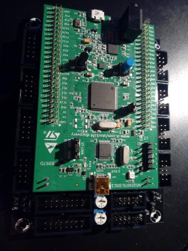
Yep, I just stole beautyofdecay_ case design as I never got around to it myself and seeing his lovely one made it easier to decide to upgrade. Got the BLM/TPD from ilmenator ofc, had the case, so wasnt to bad a deal to finally have it done :)
So many thanks to the beauty and the ill ;) Still to do: Fix one led on the BLM that doesnt light up (button is fine) and calibrate CV-out.
-
Solved. The main reason for bezels which I didnt include was the cause ... going from plastic panel to metal I discovered there was several leds that had an open side to the panel, shorting some legs to ground/panel. Havent found them all yet, found three at first, but confirmed that all is as it should be without front panel. Luckily I had used several days on a similar problem with a synth repair, those leds will drive you nuts unless youre aware of the possibility.
Aaaand 13 leds later its allright ...
-
After the stm32F4 core was made available, and there finally was some fine fpd files, BLM, TPD etc I decided to upgrade my Seqv4 in the style of beutyofdecay_
However, after upgrading to STM, finally getting application running and setting up HW file with the one for BLM then TPD as a beginning, Im having problems with the wilba panel.
BLM seems to work as intented, as well as TPD, but Wilba does not correspond properly to the functions when I press the buttons, utility and others are moved, choosing tracks show several leds lit, etc
Has there been another version of the CS panel since 2009ish? Mine is the blue 2009 version. Its the same result with every version of the wilba basic configuration.
Its the same behaviour even without BLM and TPD connected. Attached is the HW file.
At startup buttons Track group 1 and 2 and track 1, track+parameter layer 1, edit, mute, pattern and forward light up green.
And as said, even though buttons will light up when pressed, the functions do not correspond to panel/expected.
Panel was working fine on LPC17 core. -
And its alive :D A combination of using bin always, setting to single midi, changing device name, changing around different B usb cables ... i finally found mios32 device over midi and could flash :)
-
Im uploading over USB as in all posted examples, apologies if that was unclear (wasnt really aware ST-link was a dongle programmer as well) ... but yes, Ive tried that, no difference.
-
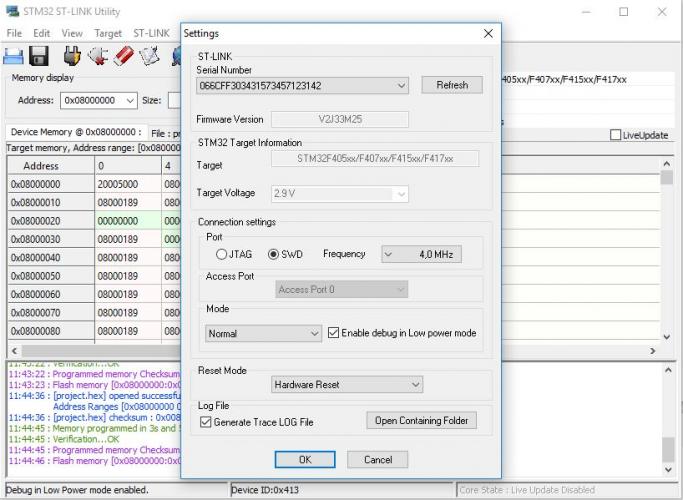
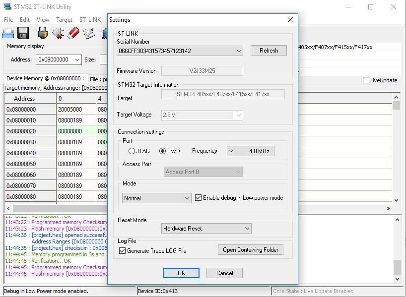
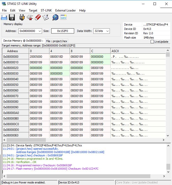
Yep, tried wipe, tried using both bin and hex file. Settings in ST-link as attached (default).
Should I try uploading with another programmer than ST-link? If so with what fuse settings etc?
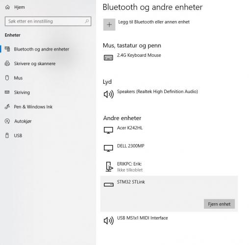
Still inclined to blame windows as I see no midi device from STM no matter what I do.
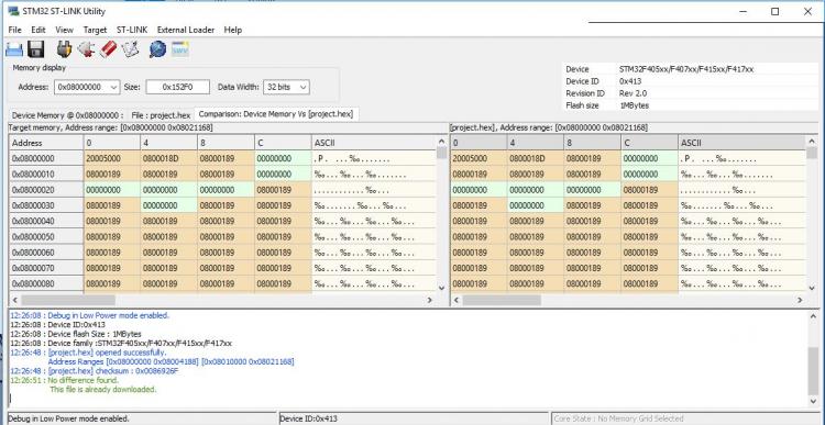
As for core jumpers J1 on STM as well as the two for ST-link is jumpered. Comparison in ST-Link finds no problem.Is there a way to force it to boot from user flash memory?
-
Nope, nothing wrong there. Would I need to have both the USB connections in? I jumpered from 5V to PA9 so i wouldnt have to.
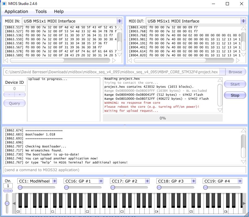
The problem seems to be that when I press start in MIOS the connection to the core immediatly drops, but after the upload fail (few seconds) it reconnects saying bootloader cant be entered.
Ive done nothing to the settings this time around, but I tried various settings in help(limiting to one midi etc) yesterday. Device ID, name etc updates so theres obviously contact.
Also tried hold blue, press black, continue to hold blue ... but then result is that it loses contact until I release blue again (thats the screenshot asking me to reset the core).
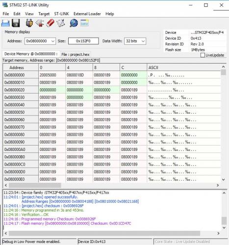
Attached screenshot for successfull bootloader programming. Also finally shows up as STM in device manager.
-
Yes. Might there be some setting for the STlink program that has to be right? Reset mode or something?
Also all that is connected now is the core itself and a single midi i/o board. No sd card text file, no jumpers except midi power.
I dont see that it should matter, but just mentioning in case its relevant. -
Yes, firmware is updated, stm is from mouser (407 IC MB997 model, so knew I had to update). I used ST-link.
Tried reuploading bootloader and different versions of the 0.95 files (there was 2014 and 2018 versions), still same.
Is there some setting in the help commands that might help? -
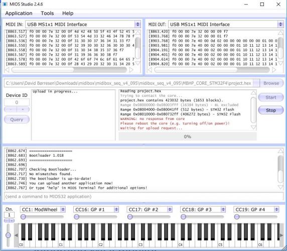
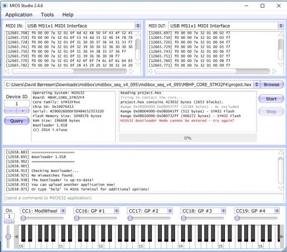
Intstead of relying on usb midi from stm I connected main board and one of the midi cards and got as far as this, where if I just have it connected it is recognized as up to date bootloader, but drops out when programming ... or as this while cycling and holding blue button, where it gets no core response.
-
As title, upgrading from lpc17 to STM ... Ive installed bootloader, but win 10 simply wont find the device and my old mac either (that I could find no midi app for).
Trying to connect via USB, both USB cables connected (big for power and small for midi).its not being recognized as an audio/other device but as a disk. stm drivers are installed as admin, ive tried both with disk option type stm when upgrading and without. Other midi devices over usb do appear, asio4all installed.
Known problem? It simply wont show on windows so obviously a windows problem, but maybe one someone has solved I hope.
Thanks for any tips. -
Ok, ill pass. Im not EU and assume hes not VAT, so its another 25 percent and much handling on both box and panel for me.
Was hoping a lowered price would offset that but at cost I have to make same decision as when I saw it offered first.
Especially as what Id really like most is a box like the ambika has, simple folded, wood sides, white with print :) -
Yes I understood that, but as Id be needing panel and backpanel I was wondering if you had made inquiries about the total price?
And your price is basically same as you were paying so Id just be taking your spot? -
I might be interested, got the acrylic, but would like an upgrade ... whats you price, and is there a quote for the panel and backpanel?
-
Check if he did the same stupid thing as me ... changed the regulators around.
If it is I just saved you the week+ it took me to find that out ;)
Symptoms were pretty much the same. -
Solved .. and in my defense it was almost the first PCB I soldered a couple years ago ... the regulators were switched.
Desoldered the 33, clipped and changed the 7805, swapped, and confirmed working, now to dive into it properly.
:smile:
Definetly owe you beers ...


"Searching SD Card..." hangs more often on bootup
in MIDIbox SEQ
Posted
Check the orientation of the regulators on the lpc17 board, I had a similar problem when I had one connected backwards.