jab
-
Posts
49 -
Joined
-
Last visited
-
Days Won
1
Content Type
Profiles
Forums
Blogs
Gallery
Everything posted by jab
-

BLM16X4.ngc - Invalid flag in EVENT_LED_MATRIX
jab replied to jab's topic in Testing/Troubleshooting
Thanks TK! Will test out tonight :) -
Hi folks - Running MBNG v1.032. I'm doing some testing with the BLM16X4 sample, but I get the following error at upload/runtime: [233770.480] AUTOLOAD 'blm16x4' [233770.480] [MBNG_FILE_C:46] ERROR: invalid flag in EVENT_LED_MATRIX ... colour=0 (expect 0..2) [233770.490] [MBNG_FILE_C:50] ERROR: invalid flag in EVENT_LED_MATRIX ... colour=0 (expect 0..2) [233770.490] [MBNG_FILE_C] Event Pool Number of Items: 16 [233770.490] [MBNG_FILE_C] Event Pool Allocation: 658 of 24576 bytes (2%) [233770.504] Patch 'blm16x4' loaded from SD Card! [233770.513] [MBNG_FILE_R] /blm16x4.NGR (optional run script) not found [233781.771] [FILE] Download of 3334 bytes in progress (0%) [233781.848] [FILE] Download of 3334 bytes finished. When I change the cc sliders in mios studio, only the green led's light up. I have also triple-checked that the SR config matches my setup. In addition if I run the rgb_1 sample everything works as expected. Am I doing something wrong? Or did I uncover a bug? Thanks in advance!
-
Very cool! Are there plans to adapt this for MB_NG? I'm interested in building an external pedal board that will have some additional DIN/DOUT inside. Or is there a simpler way to do this if all I'm looking for is extending the SRIO?
-
No reply to my PM... is he on extended vacation?
-
Not sure if there is a difference between boards produced by EA/NXP (my understanding that it was something of a joint venture and there was only one manufacturer, but perhaps not?). For what it's worth, I looked back to my thread on the NXP forum, and EA did eventually document the change: link
-
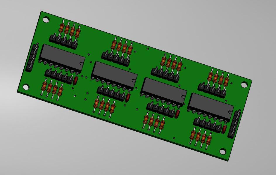
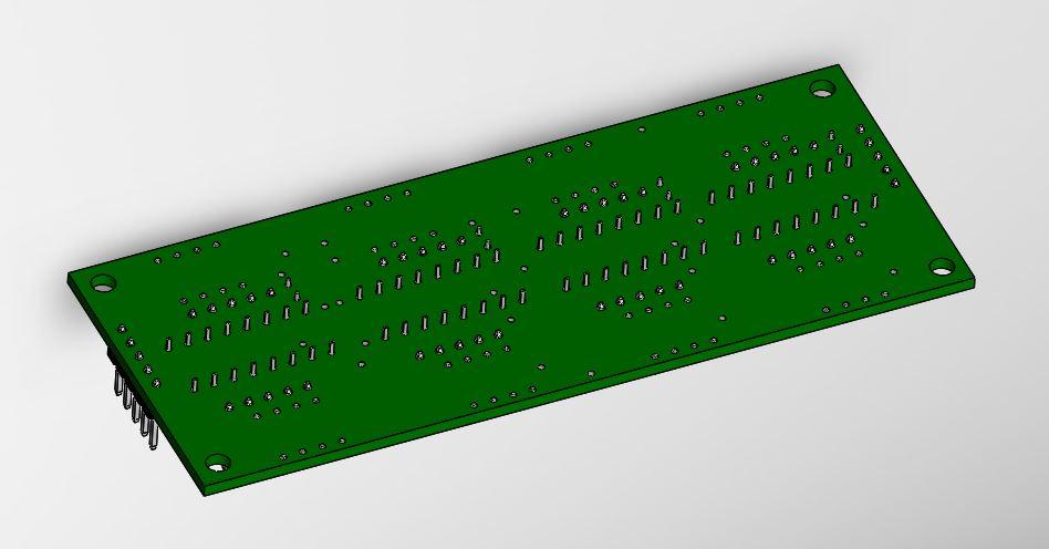
Thanks, and these are not just renderings - these are parametric models that can be used with CAD software! So potentially stupid question here: are the DIN/DOUT/DIO_MATRIX boards that SmashTV sells based of his own layout/design? Or are the .brd files available somewhere?
-
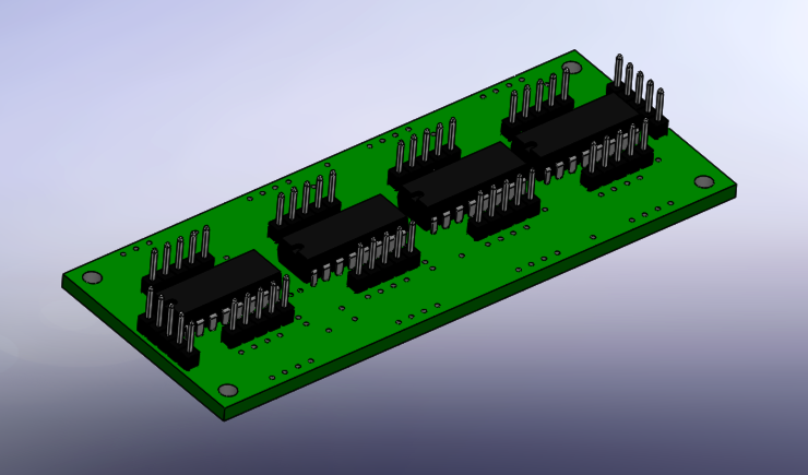
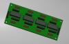
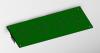
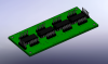
Sooo... here's the deal. Eagle v7.1 has a BRILLIANT ulp to export to IDF. So far it seems to be very smart, just need to move the board outline to layer 20 and it will output an IDF file readable by Solidworks. From there, i used the circuit works app to associate solid models with the electrical components. The models included with SW are pretty nice, except they are drawn with the origin of the part at pin 1, while the IDF file exported by eagle sets the component origin at the center of the component. I had to set an auxiliary coordinate system at the component center, but after that it worked nicely! See attached for an example of the DIN board... Of course, after I finished I noticed that the board layout from SmashTV is different than board file on the ucapps site...
-
ah, looks like step export is described here: http://sourceforge.net/projects/kicad-3d/files/utilities/
-
well that looks cool - can it be exported as a .stl/.step/.iges file?
-
Agreed, I'd also like TK's approval. I forgot he has his own SVN repository - as far as I know CVS/SVN/GIT can handle any kinds of files, although it's really made for text/ascii sorts of files. If he's ok with hosting models there I think that would be a good solution. I also like your idea of community forks of board designs (I had to substitute some components due to lack of availability in Asia), but as with the question about models I defer to TK. **Paging TK** Yesterday I spent a few hours working on this, and I think i better understand the ECAD to MCAD process now. If the MB community is predominantly working in eagle I think I have another option to try that would reduce the need to bring boards into designspark as an intermediary step (although i'm starting to prefer designspark over eagle at the moment, but i'm an ME so I'm no authority on this subject). Also while it's cool being able to have fully detailed solid models made based on component dimensions, it's largely unnecessary for design purposes and would slow down rendering/work with large assemblies. It make sense to make simplified/detailed MBHP parts/assemblies for use in different situations. Like I said, I'm doing this more as a learning experience (and I need another hobby besides drinking) so I'm interested to see how detailed/precise I can get. Anyways, here's a screen cap of my work in progress:
-
Thanks for the input guys, sorry for not posting back sooner, I've been busy with work and don't get much done at night before falling asleep... So far I haven't had a lot of luck with this... I probably wouldn't have gone down this road had I known the challenges (to be honest, I could just make a simple model to act as a "keep out" zone for the purposes of my project), but I'm I like the idea of having an electrical schematic and board layout linked to a 3d solid model - so I guess you could say i'm committed now (or mostly just stubborn). The initial method I came across of using a ULP to convert eagle board files is pretty tedious - the "generate_3d_data.ULP" will generate an IDF file, but it requires component heights be specified on an additional eagle layer, and I haven't been able to make that work so far. So far it just leaves me a board with holes, which isn't a bad start but less than i was hoping for. If I were inclined, I could use the board and add components to it, but I'm going to look into more automated solutions first. Per ilmenator, I took a look at Eagle3d and KiCad, but as far as I can tell those generate mesh based models (think blender, maya, etc) rather than parametric models used in cad software... these tend to be difficult to bring into solid works and are more useful for visualisation. I did install kicad for testing though, but i haven't done much with it yet. The dxf.ulp mentioned by Imp is a similar situation, works to create a board, but still have to deal with adding components somehow. Novski mentioned designspark, which so far looks like the best bet. It has capability to export an IDL file that is directly readable by circuitworks and brings in component information as well. I made up a simple test board in designspark to see if this is the automated solution i'm looking for. Assuming that works, I'll have to see if I can convert the eagle .brd files of the DIN/DOUT modules to designspark - there's a note on the relevant pages: Not sure what this means exactly, but maybe worst case scenario i would just need to re-identify/map the components in designspark? For the CORE_LPC17, there's actually a .step file included with the gerber files, which is good because there isn't a .brd file. That one imports into solid works reasonably well, but the components are missing leads and other things. Probably good enough for my purposes, but I'd still be interested in rolling my own. That board actually needs an update to match the Rev C version of the LPC1769, so if/when someone gets around to that (long term these will be superseded by the stm32f4 I know) hopefully they can provide a .brd file as well. Anyways, that's what i've been up to... thanks for the feedback already provided and any more to come!
-
Hi folks - I'm working on designing my enclosure in Solidworks, and I'm interested to make some solid models of the different modules to help design my prototype. I didn't see any existing attempts like this, but maybe the community can point my towards something i could use or otherwise collaborate on/with? If not... I think I can take an eagle file (i believe a single .brd file will work), do some post-processing, and bring that into solidworks for the component modeling - it's supposed to be somewhat automatic, but we'll see how that goes. Does anyone have any experience or suggestion with this? (Disclaimer, I'm a mechanical engineer by education, but never modeled electronic components or assembled boards before) My intention of course is to give these to the community, in whatever file formats I can export. (Maybe these can be added to the GIT repository?) I'm a bit time limited though, and only have physical parts of the LPC17 Core, DIO_MATRIX, DIO, and DIN, so those would be my first priorities to make (more or less in that order). Any suggestions would be appreciated, I'll probably start experimenting this weekend.
-
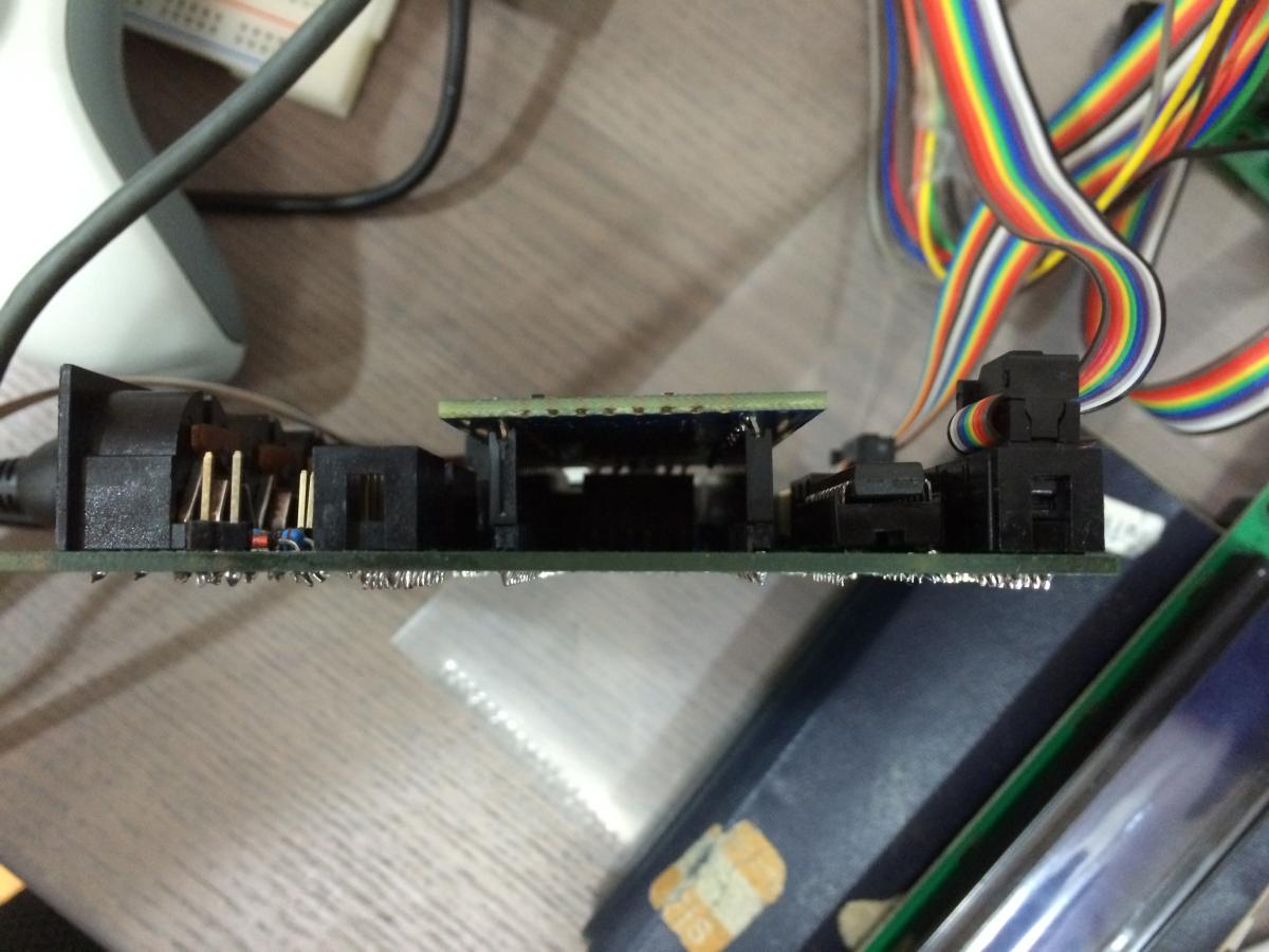
Hey guys, since there's been more discussion about this (and maybe for my own closure) I thought I'd show my solution to this, it's similar to what's been previously mentioned: I don't plan on using this hardware with anything else, but I still wanted to make the parts removable. I tried to find a method to put a bend in the male headers, but I couldn't make consistent bends, so I scrapped that idea. Then I noticed that the pins on the female headers are thinner, and could be formed pretty easily - just pressed the leads at a 30ish degree angle against my workbench, and decided to see if I could make this work So I soldered in male headers to the core module (a few pins only to start), then fit the female headers to the LPC and tried to line everything up - which took a little time but was possible.. There's a gap between the header and the pcb, but in my case the leads were long enough that I still had enough to solder to. I soldered a few pins on the LPC, and then tried removing the LPC with the headers attached - it's a tight fit, but possible. So then I plugged it back in and soldered the rest. Continuity checked out ok for all pins. I haven't tested all the functionality of my core module yet, but so far I haven't found any connection issues. LCD 1/2, DIN/DOUT, and SD card all are working well. Anyways, I'm sure my EE professors would cringe if they saw this, but I'm an ME, so I'm going to use that as my excuse ;) Not the cleanest solution, but so far it's working out, and while I don't make a point of removing the LPC, it's nice to have the option available. Hope this is some help for folks that find themselves with a rev C LPC.

-
Good point, but I'm afraid to touch it since I got it working! I'd like to work on some software for a while before go back to troubleshooting hardware... :)
-
Thanks TK - Confirmed that all the SR's I have are 74HC595, LCD I'm using is 5V. I'm in Taiwan, wonder if I got some flaky components? (Although they are labelled as TI parts)
-
So this is weird... while waiting for some advice, I made up a 1x DOUT board to test controlling outputs. It didn't work at first, and traced the issue back to the shift register. I thought I'd try that using that same 595 in the core module since I knew it was good, and what do you know, the LCD fired right up! But what's strange is that the 595 that I previously used in the core module, worked fine in the DOUT board. Maybe it wasn't seated quite right in the socket?
-
Hi Gents - I have an LPC17 core built, boot loader installed, MIDIBox NG uploaded, and SD card connected. I'm still waiting on some DIN/DOUT boards, so for now I only have a 2x40 LCD to test with. And that's where I'm stuck... LCD powers on, MIOS studio appears to detect it (I don't get a "no response" msg), I've checked the brightness and contrast pots, but all I see are bars/boxes/rectangles on the top line. So in no particular order, here's what I've looked at so far: Continuity check between LCD connectors J15A/B and LCD pins is OK (based on this schematic http://www.ucapps.de/mbhp/mbhp_lcd_2x20_mios32.pdf) Continuity check between shift register outputs and J15A/B pins is OK Enabled display on 2nd LCD using mios32 boot loader update application and tried connecting the lcd to J15B - No change Replaced 74HC595 IC with a new part - No change So now I've moved on to testing with the console using "testlcdpin", but I'm having trouble interpreting the results. With the LCD disconnected, and testing all pins on J15A with a meter, here are my findings: ON J15A/B pins RS, RW, E1, E2 all measure from 0-3.3V as expected when changed from 0 to 1 at the console Yesterday, d0-d7 stayed at 0V no matter what command I entered, but the console reported the expected logic-0 level at the d7 input pin However, today I have just retested, and now get the message, "ERROR: D7 input pin shows unexpected logic-1 level!" "Please check the D7 feedback line on your core module!" So... very confused now - any insight as to what I'm doing wrong or what I can try next? Thanks in advance!
-
Thanks for that and other support with this killer project, have a beer on me!
-
Thanks Thorsten - I took a look around the "electronics street" and wasn't able to find a 7833, best I could come with are these: 7585-3.3T: http://pdf.datasheetcatalog.com/datasheets2/59/590930_1.pdf LM3940: http://www.ti.com/lit/ds/symlink/lm3940.pdf Are either of these suitable?
-
Hey folks, I'm having trouble finding an LF33 here in Taiwan. Any suggestions for a substitution? The data sheet calls this part a "VERY LOW DROP VOLTAGE REGULATORS WITH INHIBIT", but I don't quite understand the details and I wouldn't be able to explain in Chinese (I'm an expat). Thanks in advance.
-
Very frustrating, I decided to go with the LPC17 version since it looked like a quicker path to a completed project. In hindsight, I wish I went the STM32F4 route...
-
Rev C change confirmed by Embedded Artists: (From lpcware.com forum) Seems like a completely undocumented change... I requested additional details, but not sure if they will come back with anything...
-
So I'm not the only one. Thanks for chiming in. I figure i'll end up doing something similar, but it's so weird that there isn't documentation of this change... I registered at embedded artists, but it seems like they basically send you to nxp for support. I put up a post there as well.
-
Thanks for the replies. I've been looking for information on the Rev C board for a few days now. I thought that surely this is a known issue... I didn't buy from embedded artists, shipping to Taiwan is 32 euro which is a little pricy and doesn't include customs fees. So I checked the product page and distributor list at NXP.com, and they listed Element14 as a distributor for Asia. I noticed that they have some connection to Farnell so all seemed legit. Any tips on how check the authenticity of the board? What's interesting is that the latest data sheet from NXP doesn't even list "C" in the board revisions... link I'll send a message to embedded artists and what they say. I can take some pictures tonight when I'm back from work.
-
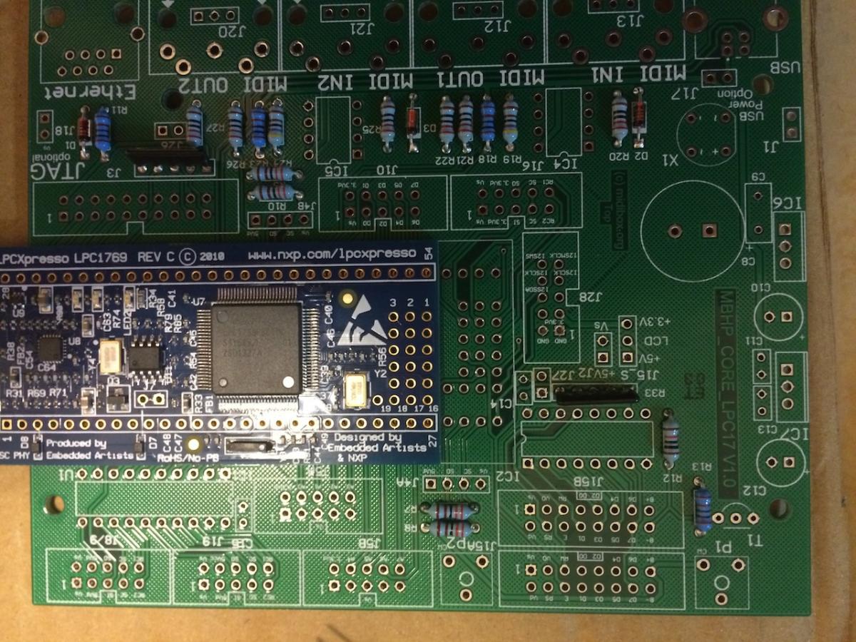
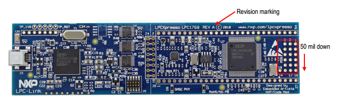
Hello from Taiwan - Not sure if this is the right forum, but here goes: Had a MBHP_Core board made up by a local pcb prototyped and had an LPC1769 sent over from singapore. Started putting things together and noticed that some of the pins on the LPC don't line up with the board, see attached. Is this a known issue with the Rev C LPC's? Update 2014.10.16: Embedded Artists did document the change: Link: Product Change Note - EA-XPR-003