

Alasdair Moon
-
Posts
141 -
Joined
-
Last visited
-
Days Won
7
Content Type
Profiles
Forums
Blogs
Gallery
Posts posted by Alasdair Moon
-
-
Im Moment hab ich davon leider noch zu wenig Durchblick, da meiner immer noch nicht fertig ist. Also auf dem Level .. ich hab die Platinen schon ...
Bin aber gerne bereit mich da etwas tiefer rein zu knien und zu helfen, wenn man mich ein bischen guided ..
-
Hab grad den Link zum smd soldering video mal probiert, der ist veraltet ... der neue Link ist
http://store.curiousinventor.com/guides/Surface_Mount_Soldering/101
Oder direkt youtube https://youtu.be/3NN7UGWYmBY
-
-
Stimmt, die page ist weg, auf nicht über andere Wege zu erreichen ...
-
Beimir auch, sowohl auf Android, als auch unter Linux, egal welcher browser...
-
Das 2te DOUTx4 für die Gates und Clock das ich als Brealout in den Modular bauen will wäre dann so richtig konfiguriert??
##################################################
# CV and Gate/Trigger/Sync Setup
##################################################

# the 8 CV gates can be assigned to a shift register (0=off, 1-32: number of shift register):
# - 1st CV Gate available at DOUT SR output D7
# - 2nd CV Gate available at DOUT SR output D6
# - 3rd CV Gate available at DOUT SR output D5
# - ...
# - 8th CV Gate available at DOUT SR output D0
CV_GATE_SR1   9

# and DIN Clock Outputs can be assigned to a shift register as well (0=off, 1-32: number of shift register):
# D7..D0 will output individual clock or start/stop signals which can be configured in the CV configuration page
CLK_SR        10

# additional gate triggers are available on common digital output pins of the
# DOUT shift register chain - they are assigned to AOUT channel #16 (Note C-1, C#1, D-1, ...)
# define the shift registers which should be used here (each provides 8 gates)
# Note that SRs assigned to this function cannot be used as LED outputs (exclusive function)
# Allowed values: 1-32, 0 disables the function, all other values invalid and not allowed
DOUT_GATE_SR1   11
DOUT_GATE_SR2   12
DOUT_GATE_SR3   0
DOUT_GATE_SR4   0
DOUT_GATE_SR5   0
DOUT_GATE_SR6   0
DOUT_GATE_SR7   0
DOUT_GATE_SR8   0
-
Nach gefühlten 200 Tagen MBSEQ_HW.V4 aus dem WebSVN Trunk, glaube ich das mir ein Lichtlein aufgegangen ist.
DIN und DOUT sind 2 separate Chains
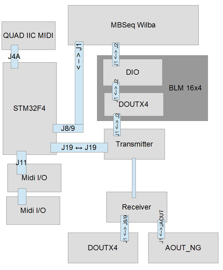
also müsste meine Theorie stimmen das die SR auf dem DIO als DIN 7 / 8 und DOUT 3 / 4 angesprochen werden wenn ich sie wie im Bild oben direkt hinter das Wilbapanel hänge.
Wenn ich mich an TKs http://www.ucapps.de/mbhp/button_duoled_matrix.pdf halte, müsste dann die Config so aus sehen, wenn ich die Cathodes und die INs auf das DIO setze und die L1 L2 / R1 R2 für die DUOLeds auf das erste DOUTx4
################################################### Optional BLM Matrix################################################### set this value to 1 if each track has its own set of 16 LEDs to display unmuted steps and current sequencer position# or if you are using a button/led matrix for misc. button/LED functionsBLM_ENABLED 1# define the shift registers to which the anodes of these LEDs are connected# Note: they can be equal to GP_DOUT_[LH]_SR, this saves two shift registers, but doesn't allow a separate view of UI selectionsBLM_DOUT_L1_SR 5BLM_DOUT_R1_SR 7# define the shift register to which the cathodes of these LEDs are connected# Note that the whole shift register (8 pins) will be allocated! The 4 select lines are duplicated (4 for LED matrix, 4 for button matrix)# The second DOUT_CATHODES2 selection is optional if LEDs with high power consumption are used - set this to 0 if not usedBLM_DOUT_CATHODES_SR1 3BLM_DOUT_CATHODES_SR2 4# set an inversion mask for the DOUT shift registers if sink drivers (transistors)# have been added to the cathode lines# Settings: 0x00 - no sink drivers# 0xf0 - sink drivers connected to D0..D3# 0x0f - sink drivers connected to D7..D4BLM_DOUT_CATHODES_INV_MASK 0x00# 0: no DUO colour LEDs are connected to the LED matrix (position marker inverts step LED)# 1: DUO colour LEDs are connected to the LED matrix, second LED displays position marker# 2: Like option 1, but the first LED is turned off when the position marker activates the second LEDBLM_DOUT_DUOCOLOUR 1# define the shift registers to which the anodes of the "second colour" (red) LEDs are connectedBLM_DOUT_L2_SR 6BLM_DOUT_R2_SR 8# set this to 1 if a button matrix is connectedBLM_BUTTONS_ENABLED 1# set this to 1 if these buttons should only control the "step triggers" (gate, and other assigned triggers) - and no UI functionsBLM_BUTTONS_NO_UI 1# optional (only useful in conjunction with the BLM):# if 0: the GP buttons/LEDs are working as usual# if 1: the GP buttons/LEDs always select the page items like if the MENU button is pressed,# the GP LEDs show the selected page (if matching with any of these items)BLM_GP_ALWAYS_SELECT_MENU_PAGE 0# define the DIN shift registers to which the button matrix is connectedBLM_DIN_L_SR 7BLM_DIN_R_SR 8 -
So, lang dauert es aber irgendwann wirds klappen ....
Zumindest hab ich die meisten Platinen jetzt .. das BLM16x4 werde ich doch durch nen Eigenbau mit 1 DIO-Matrix und 1 DOUT bauen.
Stimmt eigentlich meine Verkablung mit den Modulen so wie unten im Bild?? DIO und DOUT nach dem wilbapanel ergeben das BLM 16 x 4 ... Receiver, AOUT, DOUT werden direkt in den Modular gebaut
Muss jetzt nurnoch hinter die Logik mit dem Ansprechen der einzelnen SR kommen.
BLM hat schonmal 6 DIN SR und 2 DOUT SR
Die DIO hat 2 DIN und 2 DOUT SR ... sind das dann DIN 7 und 8 und DOUT 3 und 4
DOUT1 dann nochmal 4 DOUT SR also DOUT 5 - 8
DOUT2 dann DOUT SR 9 - 12
Oder werden die SR von vorne einfach durchgezählt .. also nach 8 SR vom Wilba wäre dann beim DIO SR 9 - 12, DOUT1 SR 13 -16 und DOUT2 im Modular hat dann SR 17 - 20 ?

-
There is www.ucapps.de/midibox_cv_v2.html that will have CV-in's. What do you want todo with the CV-in's in a Sequencer?
-
Cool, so my reichelt Checkout can be done as soon as I have the money. Thanks loderbast ..
-
Do the ITT D6R fit out of the box?? I first wanted to buy them too cause I like round simple buttons, but was unshure, cause the inner holes of the wilba panel are not 5 by 5.
-
O.k. I have not yet builded my seq, but I'm a bit familiar with oldschool sequencing ..
Ratcheting is normally done by using gates with different speed for the same sequence that runs at the same speed ... this is easy with cv / gate synths ... via midi it is a bit more difficult ..
In the midibox manual I saw that there are multiple gate / trigger layers per track
Quote:
A:Gate: the active trigger layer (A,B,C,..H), and the trigger function which is assigned to the layer
The trigger layer can selected with the TrgSel (F3) button, or with the optional Trigger Selection buttons which are part of the MIDIbox SEQ V4 frontpanel.
End Quote
Maybe that would be a possibility ...
-
wich are alternative switches ??
On the pcb it looks like multipe switches can be aplied ..
Do 6x6 mm fit as well??
What about these??
Or maybe these??
-
SOLVED I simply changed the url from irc.mibbit.net to irc.eu.mibbit.net Mibbit uses a proxy so all connections seem as one IP to it
-
Yes, must be my client and mibbit ... I get a "Too many connections from your IP" ???? Only one chatclie t nere in my house via my router ... hmmmmm
-
since one week i can not connect to the chat anymore ...
the widget works .. but my chatclient refuses to connect ..
Anyone else with this problem??
-
Just found this quote from tk about the aout ng
.......
Quote
Is the Aout or out NG accept the 15 V?
...... TK .......
Yes, the allowed voltage range is +/- 18V
Best Regards, Thorsten.
-
The AOUT can be used with +-15v?? Cool cause I have the same idea ... in my case to build the aout into modular using the line driver boards
-
Exactly that pdf i was looking for ... 64 button + duo led .. ty
And yes .. I wanted to use dot matrix boards for the switches, leds and diodes .. wire them as matrix with verowire or copper wire like this
www.reichelt.de/Kupferlackdraht/CUL-100-0-28/3/index.html?&ACTION=3&LA=2&ARTICLE=57179&GROUPID=4484&artnr=CUL+100/0,28
So if i use one dio matrix and one dout .. i have all the SR i need and only need to alter the blm part of the config file .. great
-
Hi folks,
I saw the wiki of the 16x4 BLM board
www.midibox.org/dokuwiki/doku.php?id=16x4blm_pcb
and got my hands on one from a bulk order ....
but I was wondering .. could I build my own BLM 16x4 by using standard dio and dout boards??
If I read the wiki well I need 2 DIN shift registres and 6 DOUT shift registers .. so I could use
one DIO Matrix board and a second DOUTx4 board too, right? ..
Seeing this pdf from the dio wiki page I'm unsure if not only one dio module is enough
http://www.ucapps.de/mbhp/mbhp_dio_matrix_8x16buttons_8x8leds.pdf
Do I really need the dual color leds?? Hmmm .. maybe if tracks have different lenght ..
My question is .. could someone show me how I should tconnect the buttons and led to the shift registers?? .. best in form of the nice pdf files tk provides us with.
Advantage for me would be that I can bring the buttons in line with the Seqv4 wilba design and also use the same switches ...
Or would it be much easier to use the MBBLM via Lemur .. for Lemur now is available on Android too???
-
@jaytee: Normally you could also do the same with some din and dout or an i/o matrix board .. be aware that the IC on the blm are SMD and you have to go with the marquardt switches and the layout is not lined up with the upper 16 rotary encoders
-
Habs mich getraut .. Bestellung ist raus .. gleich nen 2ten Satz für meine Liebste mitbestellt (ja die mag Elektronik und findet löten sogar entspannend .. also selber löten .. nicht nur zugucken)
Irgendwie freu ich mich wie Hulle darauf bald ein Midiboxer zu sein ..
-
Danke sneakthief,
Konnte gestern noch mit SmashTV chatten ... PCBs sind komplett da ja das wilba board die din dout vereint die man benötigt. Grosse Bestellung geht heute raus.
Für den Rest hoffe ich ja immernoch irgendwie an Farnell zu kommen die in Lüttich sitzen .. die haben auch den tlv5630 dort auf Lager. Für Farnell.de gilt ja ... Nur Geschäftskunden ... bei Farnell.be steht einfachn nur .. als Privatperson nur Bestellungen über 50€ .. Ich probier das einfach mal ....
-
Ja .. die bekomme ich ja bei reichekt o.ä. ..
aber die PCBs für ne Bestellung bei SmashTV müsste komplett sein wenn ich mich nicht ganz vertue ...
Muss nurnoch gucken wo ich das stm32f4discovery und den tlv5630 her bekomme .. bei mir um die Ecke in Lüttich sitzt Farnell .. weiss aber nicht ob ich da mal ebenso als Normalsterblicher einkaufen kann ...

The Flatsequencer (MBSEQ V4 with TPD, battery powered)
in MIDIbox SEQ
Posted
Woooooowwww ....Buildmaster ..
Sieht Hammer aus