

p4rancesc0
-
Posts
7 -
Joined
-
Last visited
Content Type
Profiles
Forums
Blogs
Gallery
Posts posted by p4rancesc0
-
-
Hi Julian , any news on this beautiful case ?
Cheers
Frank
-
Hi,
I was thinking exacting the same...
I don't know what cowboy is going to do, but I was one of the beta testers of the mb909 (a sequencer for the tr9090) and I'm pretty disappointed that the project is gone...
I've lost hours in finding bugs on an incomplete software and now that everything seems to be over I can't still access the src code.
Why I'm telling this here ? It was a branch of the seqv4 but the hardware was build with dogm 240x128 display and the usability was a total nightmare, not all menus were backported. The main problem is that I intended the mb909 like a master sequencer with a 909 in front and not like the 909 sequencer...the work for back porting all the usability to that display ... really can't say but a way too much when the software is maintained and documented when using the right display configuration.
I still think that It would be great to have a fully working seqv4 inside the enclosure of a 9090 and control with it other synths, but I need to make another pcb with teh rght buttons and the right displays this time!
More ore less like "cowboy"
Any other hints ?
Any eagle schematics out there ?
Anyone willing to start another drummachine / workstation prototype ?
Please feel free to move this to another topic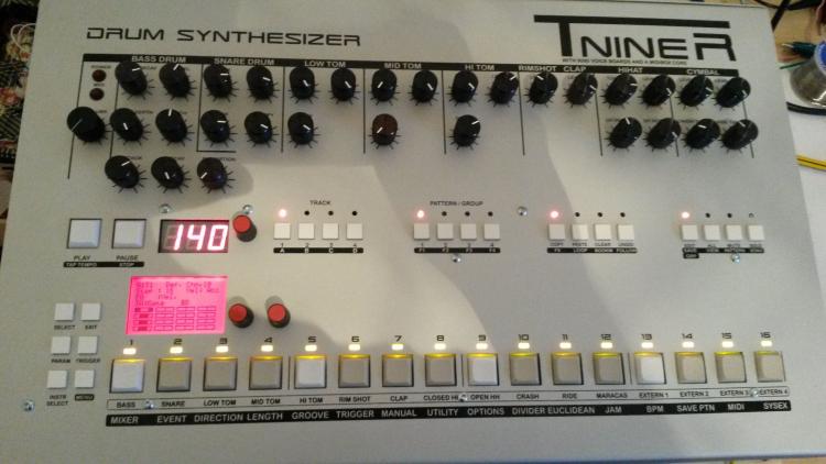
-
U1 on the STM32F4 it's cold... I think it's the 3V regulator. The LCD + backlight should be less than 40mA.
Any hints on the ugly SPI signals ?
-
Just now, Shuriken said:
To get some things clear:
- Do you provide power through USB or J2?
J2, with a reulater 5 V 2A psu
- What Port are you using to connect the DOGM lcd?
I'm using J15A
The MBHP_CORE_STM32 which is mentioned in the pdf is not the same as the MBHP_CORE_STM32F4 you are using.
Thanx! Is out there a connection diagram from the STM32F4 and a DOGM display... I think I'm having issued with the SPI lines ... signals are really ugly... LCD a lot of times crashes ... 1M resistor (the oscilloscope probe) partially solves the problem and makes the MB909 usable for a longer while -
Hi,
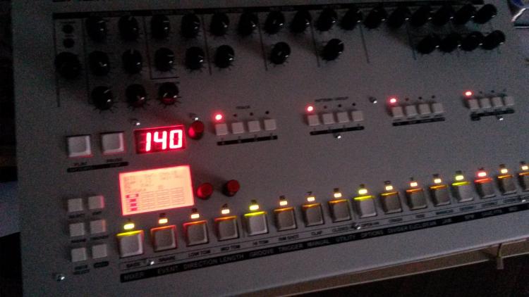
I just finished building a CORE_STM32F4 with a MIDI_IO Module. It's connected with a MB909 MK-IV board but this is another story.
I've noticed that 3V output, VDD output are @ 3V... I'd expect 3.3V ...
By the way I'm looking into this because I've having trouble with the LCD: it's unstable.
The best way to replicate: hold EDIT button, it makes at lot of message on the SPI, after few seconds the DOGM display becomes full white.
The core is supplied with a 2A PSU. The sofwatre doesn't crash, can see SPI messages after LCD "crash".
Anyway, the question is:
3V core pin, VDD core pin: are they normal @ 3V or they should be @ 3.3V (at least VDD @3.3V) ?
This document is confusing me:
http://ucapps.de/mbhp_lcd.html
this PDF:
it talks about the 3.3V but it's unclear where I can get it on the STM32.
Thanks
-
Hi guys, I've got the same problem.
I'm in Italy and I'd rather avoid 20E from mouser.
I see that alternatives could be 693063010911 Wurth Elektronik , so this one could be Ok ?
http://it.rs-online.com/web/p/accessori-per-connettori-per-memorie-e-sim/7636794/
sorry to bother but I'd like to double check.
I see it only has 9 pin, the 3M one wasn't 11 pins ?
Thanks in advance
Francesco


Possible new case option, without needing Heidenreich group buys
in MIDIbox SEQ
Posted
My pcbs just arrived, still waiting for any updates !
Cheers
FranK