

Nirokesan
-
Posts
46 -
Joined
-
Last visited
-
Days Won
1
Nirokesan's Achievements
MIDIbox Newbie (1/4)
2
Reputation
-
 What knob are you using for data wheel?
 -
Issue with Sign-up and Contact forms, not working
Nirokesan replied to Nirokesan's topic in Miscellaneous
Welcome! Glad I could help (though I had the smallest of parts) -
I received an email from someone attempting to sign-up for the forum. He says the sign-up and contact forms are broken. I tried to create a dummy account and could not pass the security screen, and I'm sure I had the correct answers. Can someone look into this? Is there another thread already discussing this? I searched and did not find one. thanks!
-
Thanks for the help. I don't know that this is "fixed", but I too logged in using my username after resetting a password and it seems to be working. Cheers!
-
I just looked at my account settings and it shows my password being 8 characters long but the password I just created to log in and write this post is 12 characters long
-
This is terribly frustrating. Every time I try to log in, I'm told my password doesn't match. I request a change, change it, write it down, and next time it's "wrong" again. Why is this happening?
-
I opened the 303 and tested the socket connections which all seemed fine, but there was no solder on Pin 2. Maybe it broke free from the pad and pin? I don't know. Added solder there and reflowed the other pins. Works fine now, trigger length is 3-4ms here, can't remember
-
https://i.imgur.com/7CDCKkM.gifv DIN Sync out via the DOUT Clock+S/S SR# works fine with my 606, however, I needed to use a trigger length of 2ms at least otherwise the 606 played in some broken sort of half-time. The above GIF shows a trigger length of 3ms (maybe 4ms) and a tempo of 128 bpm. So the failure I experienced before must be the fault of my 303. I've tried with two different cables that have both been tested for continuity. I just did a test between my 606 and 303 alone and discovered some irregularities. Both units play fine by themselves. When I connect the two together, the clock rate on the 606 also flashes on the 303 showing that the clock is getting through the socket and interrupting the internal (this is different from the connection to the DOUT as the MIDIbox clock is not running until you press play). When I press Run on the 606, the clock on the 303 stops flashing but the Run light is on, no sound from the 303 (just like with the MIDIbox). Obviously I need to look at the schematics and take this issue elsewhere. (edit: looked at schematics, a bad pin 3 solder joint on the 303 socket could be the problem. Will examine) Bottom line is.....DIN Sync from the DOUT works just fine if the trigger length is set larger than 1ms (increase if necessary), I can keep my breakout box design, and I can use different timing divisions.
-
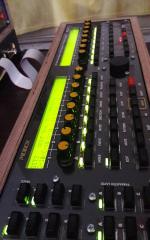
Thanks for your reply, Gerald. Yes, I'm using SeqV4 with latest software. I cannot test J5B without disassembling my sequencer enclosure, and I'd prefer not to if there is another solution, especially as there is no room on the rear panel to add any more ports. my hardware and config file are all set up as you can see in this GIF : https://i.imgur.com/BFUeDRB.gifv The right-most column of sockets and LEDs is showing the SR assigned to clock and start/stop. You can see that I have different clock divisions set for the separate clock outs, and all Start/Stop outputs are held "high". I'd prefer to use this DOUT SR for DIN Sync to my Roland gear since I can supply different clock divisions to each machine, and because the case is already built with the provision for two DIN ports. The questions are....why is this DOUT SR failing to drive my 303, has anyone else got this working with STM32 and DOUT, and how?
-
I thought this was going to be simple, but I haven't got it to work. Is anyone using a DIN Sync out with an STM32? I searched the forum and most of the posts involve the older core and boosting the signals from 3.3V to 5V. During my build, I just assumed that I could use a DOUT SR set to clocks and start/stop, wire a pair to a DIN Socket, and be good to go. That didn't work. I thought perhaps I had the pin-out of the socket wrong (top two google images for DIN Sync out contradict one another), but swapping them didn't work either. In fact, one way made the Run light of my 303 come on, and the other way made the selected pattern light flash. I don't get that. I traced the signal from the 303 back thru the cable and believe that the correct configuration of the socket (face side) is: clock S/S NC. NC Gnd I started looking into DIN Sync standards and read that the clock should be a square wave and should have a delay of 9ms for the first step. Could this be the issue? I also read in the other threads mentioned above that some people got the Sync to work from the old core using clock lengths of 3-6ms (this must depend on the chosen tempo, not optimal). What are my options here? I'd prefer to use the Clock SR from my DOUT as the Sync sockets are already built into that box, but if I'm forced to connect directly to the STM32, I will. Thanks for any advice/shared experience. Surely someone must have DIN Sync working from the STM32!
-
https://imgur.com/a/dwaIr made this quick GIF to show the breakout box and LED drivers in action.
-
-
Thanks, yes I know in this case the offset is only for the bipolar null adjustment, I meant that other devices have an offset and scale (VCO, VCF, etc) It might have been a good idea to make the AOUT_NG accept a through-hole socket so the SMD DAC could be soldered to an adapter board and easily swapped out to find a good one. Although, this isn't like swapping out a transistor. $$$ Can you share with me the values for your channels (what you've decided is usable and unusable)? I haven't tried an "ear test" yet, still waiting for my new output boards to arrive. Maybe I won't even notice the non-linearity, it amounts to 1cent between 0-1V, half a cent from 1-2V, but not too bad above that. Perhaps I can just use from 2V and above and pitch my VCOs down, I'd still have a decent 6 Octave range.
-
Can we agree on a procedure and update the WIKI page? I did a preliminary calibration of my board last night. I assume I did it correctly, but maybe there's something I've overlooked or misunderstood. Basically did this: 1. Connect DMM to output header pins. 2. Select 1V, adjust scale trimmer so DMM reads 1V, repeat up to 8V. (Of course, now my 1V is off my an average of +10mV and 2V is off by +4mV) 3. Switch to bipolar modes. 4. Select "middle", adjust bipolar trimmer so that DMM reads 0V Is this correct? Usually when adjusting something for v/oct, there is a scale and an offset trimmer, right? That way the scale is correct across the full range. Perhaps I need to first monitor the outputs at "min", then add that value to each test level? Or do I just have to trim back the 8V result to 7.997V or so to get 1V result back closer to 1.000V? thanks!
-
[S] TPD (Track Position Display) full kits for sale
Nirokesan replied to ilmenator's topic in Fleamarket
I understand. How exactly do the LEDs correspond to a track position? I can't tell what I'm seeing in your breadboard video. I appreciate your help,
