voronin75
-
Posts
17 -
Joined
-
Last visited
voronin75's Achievements
MIDIbox Newbie (1/4)
0
Reputation
-
Thank you very much, you helped me a lot! SHIFT + track 3 (extra coll.) ---> mute/unmute function of track buttons
-
So the problem is generally solved by RC filter (with 100 ohm+100pF in serial to gnd) at the end of the SC line. (does not work with the second filter on the RC line) But there are two questions - the SHIFT button does not display BPM (led is ok), and the exta buttons column work only as a track selection, but mute / unmute does not work (although leds displayed if mute / unmute on SEQ) I will search, but maybe there are any ideas?
-
Grounding on the chassis I meant the direct connection of the last SC output to the ground of the power supply. Without RC shunt termination. Everything works well with one exception. when you turn it on, you must reconnect the SC-> GND bus) Otherwise the device does not start correctly. I am an amateur))) I will try.
-
The problem is solved by connecting the last output in the SC chain to the ground (to the main chassis ground, not the last board gnd) It works correctly and stably. I still do not understand why. Can someone explain? Or i missed something? I found the answers here. I think this is what latig on said.
-
latig on thanks for your answer! The grounding of the blm power supply is connected directly to the seq ground. Can you explain buffering the J8/9 signal and/or terminating the chain with an RC shunt.? 74HC125 chip on minicore is buffer, right? Works fine only two scalar in different combination CS setions. How check SRIO integrity? Here short video of trouble https://fex.net/uk/s/slzdkay
-
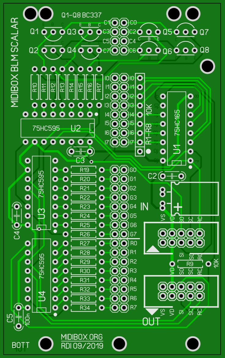
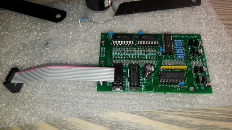
This is my version of SCALAR. Mount under main pcb to dil socket.

-
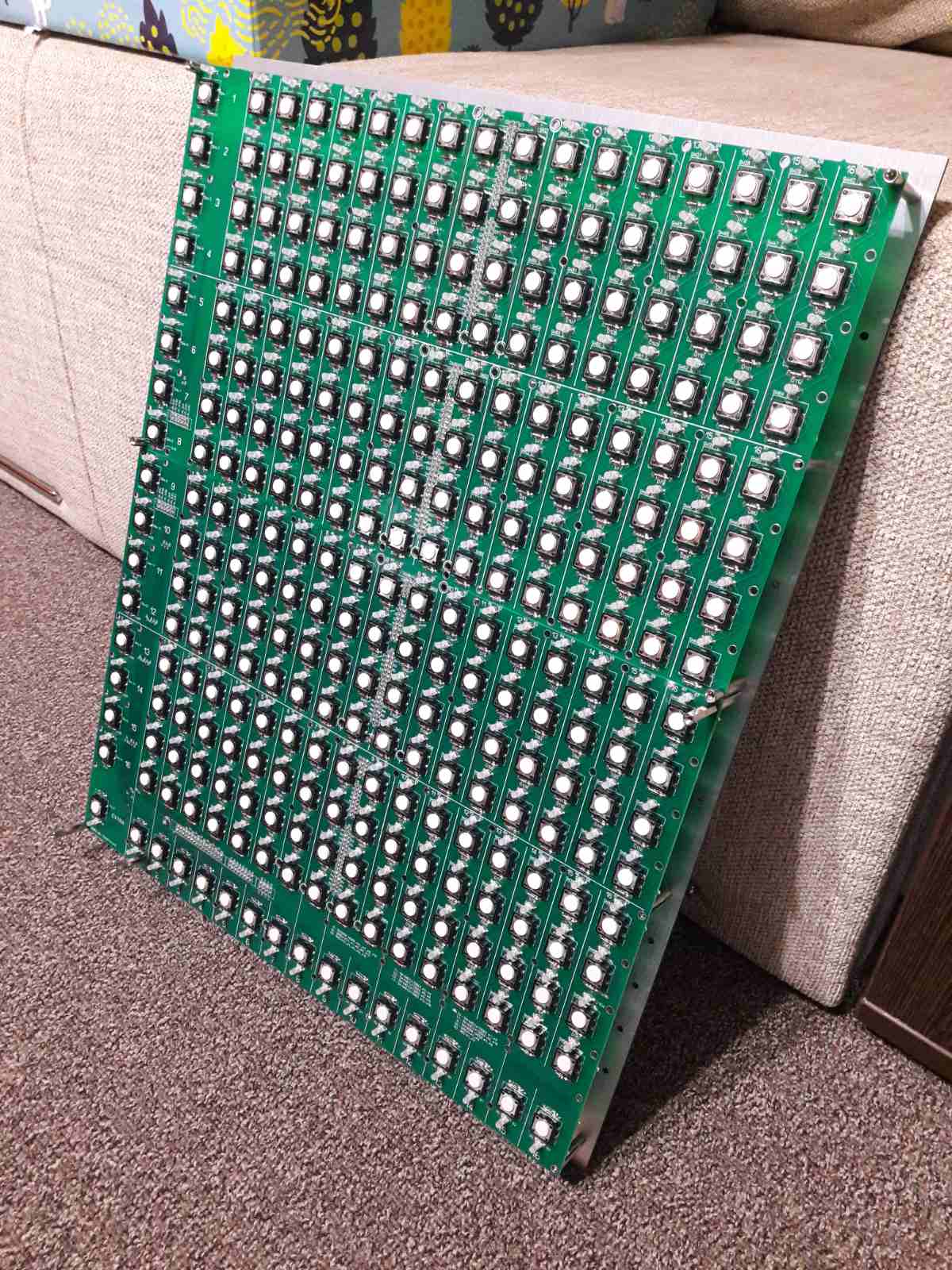
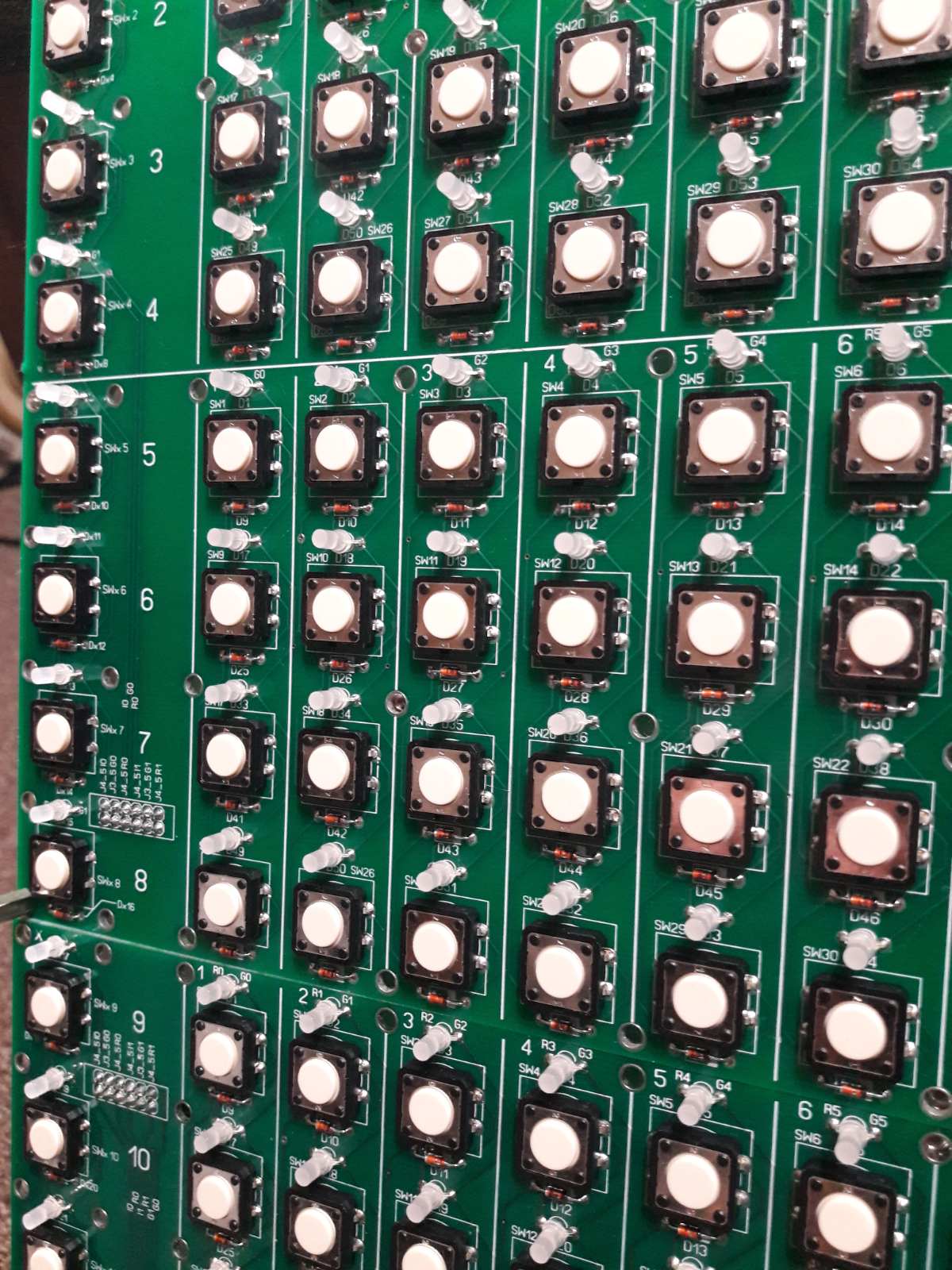
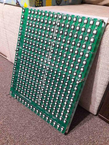
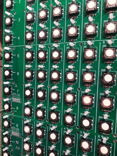
Hi all midiboxer) Need your help! I built blm 16x16+X on PCBs. CS consists of two printed circuit boards: the first contains 16+Xx8, 2 scalar modules are installed under it, the second 16+Xx8+X contains 3 SCALAR modules The device connects to midibox seq v4 normally on port IN3 Firmware PIC4620 blm_scalar_v1_1, Power from 5V 3A power supply Test of the first section 16x4 with SCALAR module -ok The next section test is 16x8 with two SCALAR modules -ok Test of the next section 16x12 with three SCALAR modules - all the LEDs blink, the buttons transmit the midi event to the midi monitor if you click Section test 16x16 + extra - the device goes crazy, all the LEDs are lit randomly, the buttons transmit the midi event to the midi monitor All the same if you change the scalar modules in any configurations, the same if you connect the modules arbitrarily on the board i.e. e.g. starting at line 5, etc.) Those. Errors on the PCB seem to be eliminated, on the scalar, it seems, too. Remains Core (voltage drop in the last scenario to 4.9V) Connection length between SCALAR modules about 100mm jumpers on Core J5 are not installed as stated in the description of the firmware project_without_ain.hex (the same result with jamper) Has anyone come across? Please tell me where to look? Regards Modules are installed under CS and connected by a ribbon cable about 10 cm

-
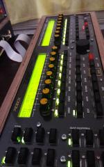
New completed MIDIBOX SEQ V4 with friends
Images added to a gallery album owned by voronin75 in MIDIbox Gallery
New completed MIDIBOX SEQ V4 + CV / Gate module (base on LINE DRIVER, AOUT NG and DOUTX) with MFOS Sound Lab Mini-Synth MarkII. Made in Ukraine. -
-
Solved. Short under the IC socket. Thank you for attention.
-
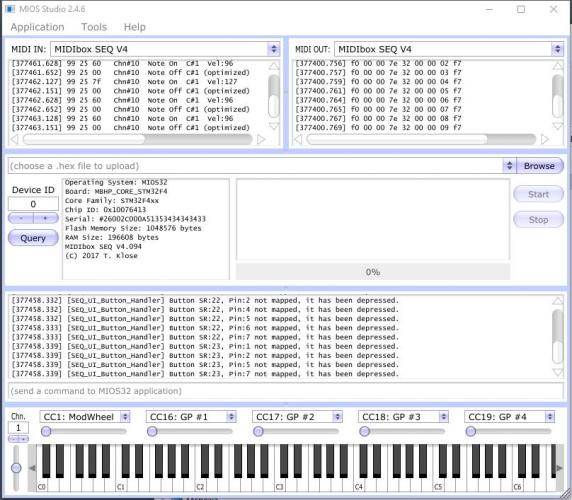
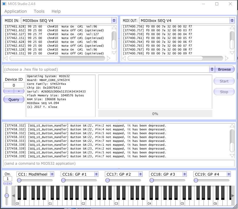
I have seq v4 with wilba CS working fine. I add the line driver + aout ng modules connected by scheme for seq users from www.ucapps.de/mbhp_line_driver.html (j8/9 of core to j1 cs; j2 to j2 transmiter; j19 of core to j19 transmiter etc.) and in result have crazy seq.(screenshot) and MC3486, MC3487 seems warm. Check for shorts on line driver pcbs- all fine. Pinout seems normal. Some result without any connection fron transmiter. AOUT seems work fine. Tell me please where to look for error. Thank you.