

knochenfabrik
-
Posts
29 -
Joined
-
Last visited
Content Type
Profiles
Forums
Blogs
Gallery
Posts posted by knochenfabrik
-
-
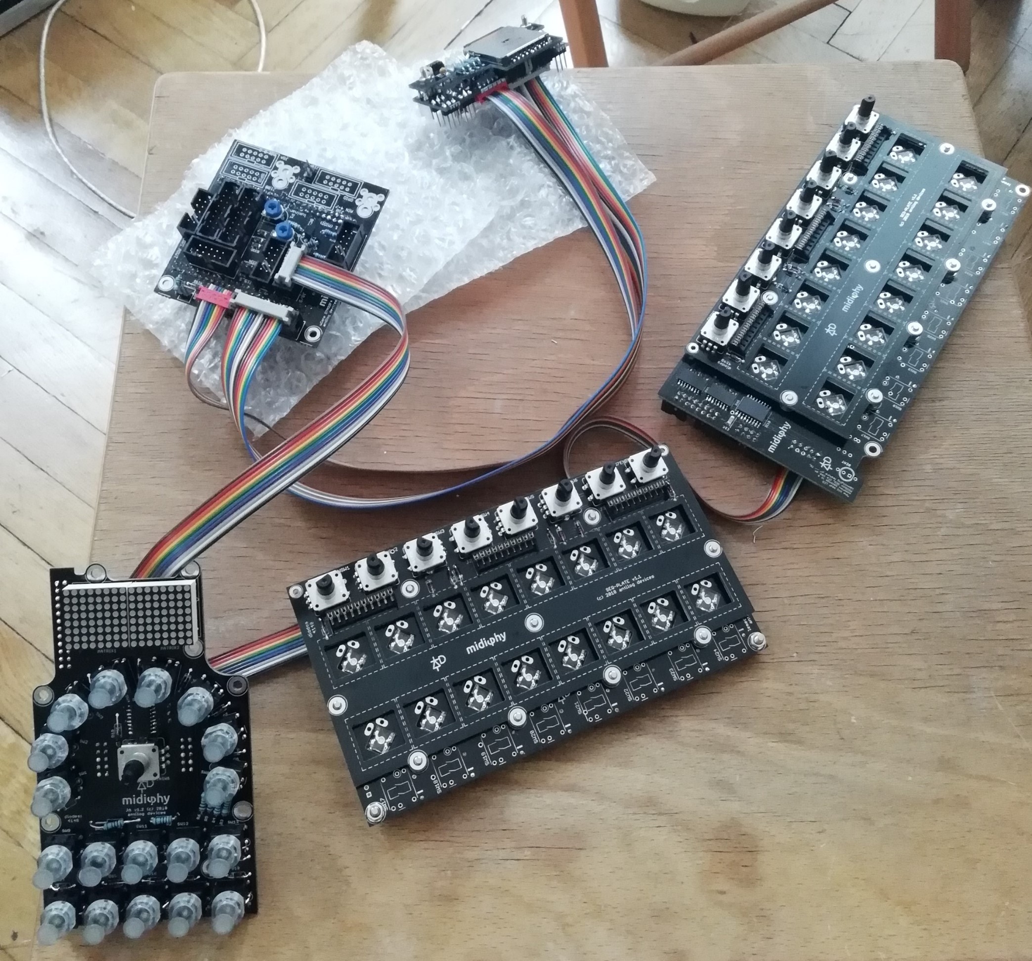
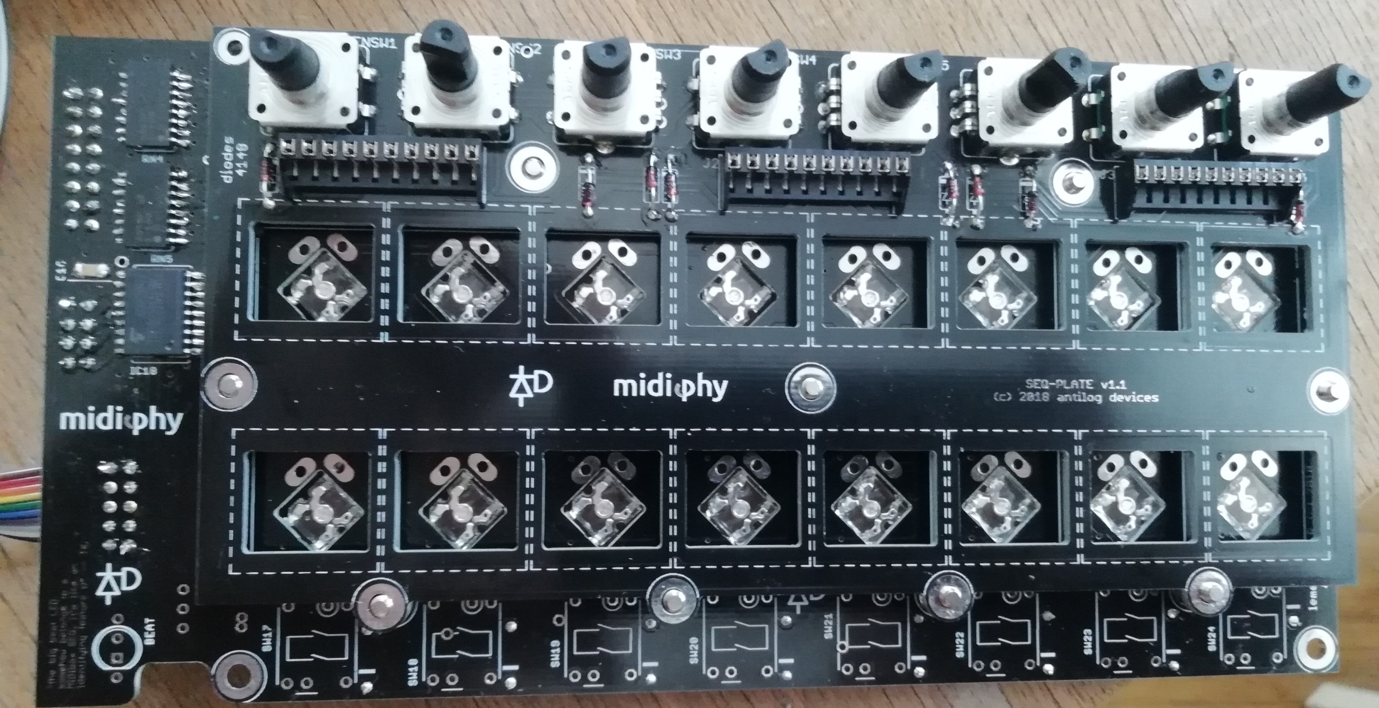
Hi guys, made some progress and mistakes so here I am again. Finished the JA and both Lemec-boards. JA-board was working find when tested with MIDIBOX_NG (with Midibox App all LEDS in the lowest row start to light after ~5 sec of powering on - the green LED doenst light up - in MIDIBOX_NG it works just fine when clicked though)
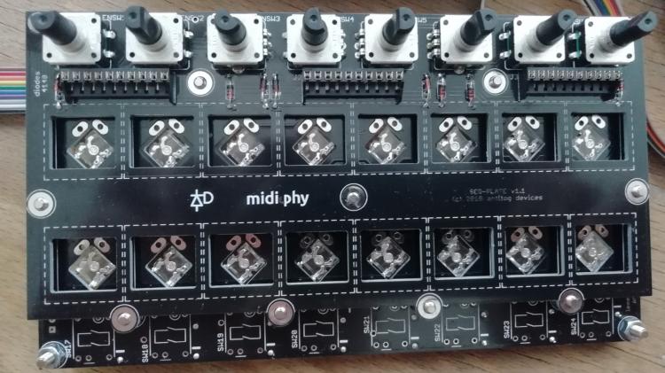
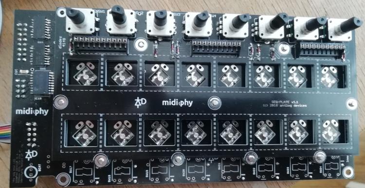
So i went on to test the Encoders and Switches on the LEMEC boards. On the left board (first in chain) all of the Encoders work
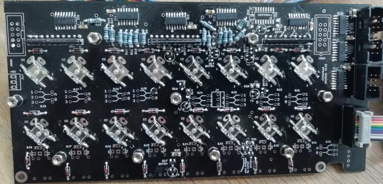
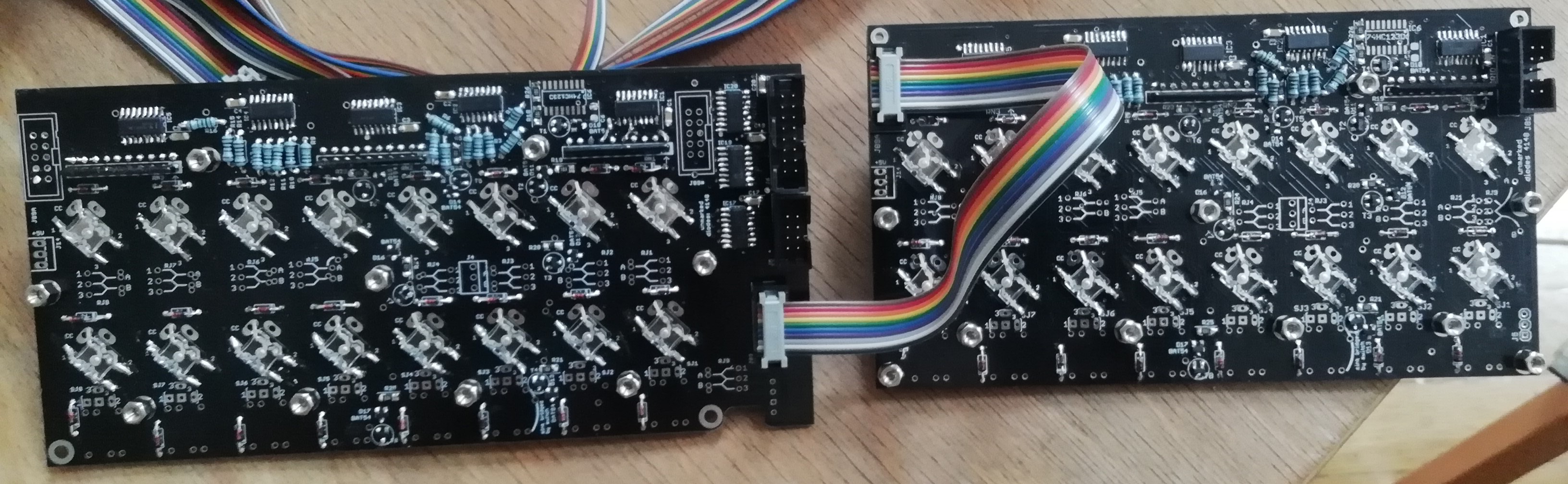
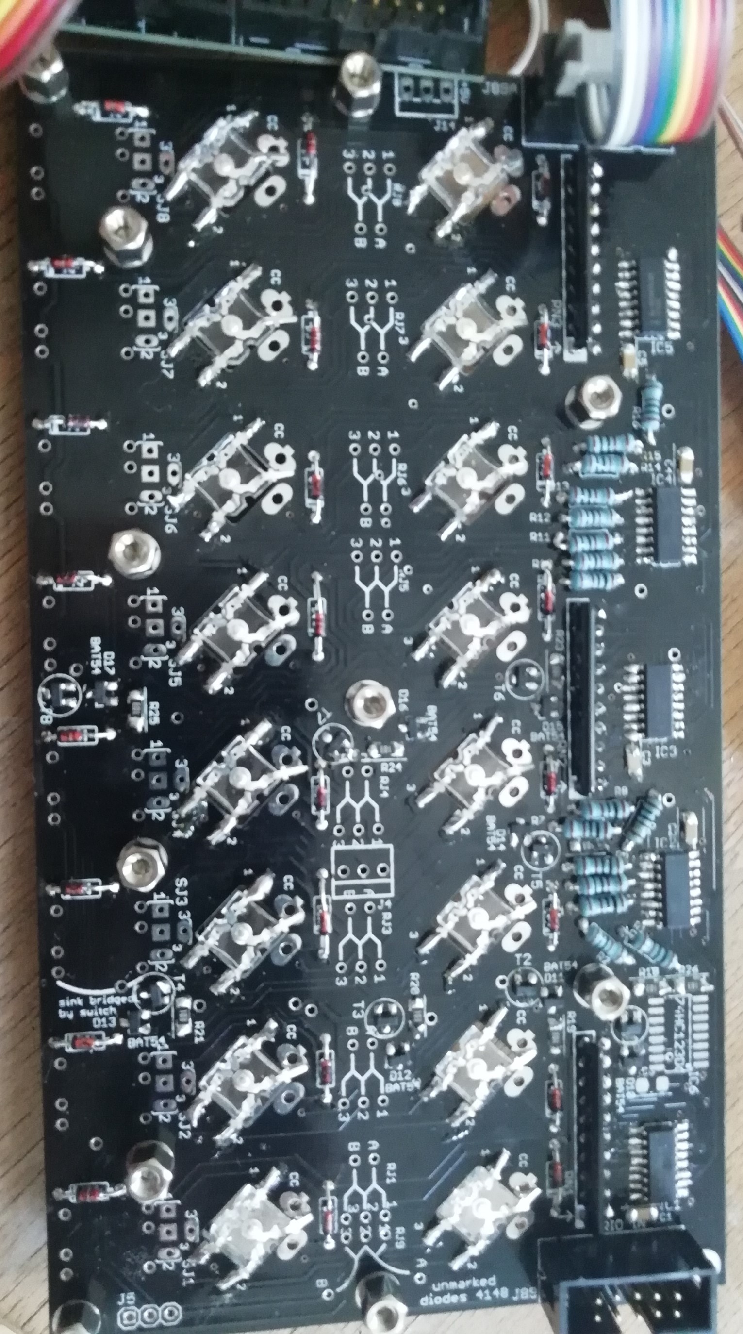
and One single Matias Switch doesnt work (The one in the down right corner - 2nd row, 8th column)Had the 4148 Diode in the wrong direction - now it works perfect. On the right board (2nd in chain) none of the switches and encoders work and when everything is chained together for DIN test alle the 16 encoders dont react. I had to "air-wire" IC1 on the right board since i removed a bit of pad and traces on 3 pins of the 10 pin header (see photos attached).Tried to resolder IC17 on the 2nd board and now it seems that if its connected none of the encoders on any board work - if i only connect the first board to the JApcb it works perfectly fine.
Also when i only connect the RH pcb (2nd in chain) to the JApcb the LEDS and switches on the JApcb wont work and i get this message when loading SEQ_R
"[7621.268] load seq_r
[7621.630] [MBNG_FILE_C:1] WARNING: unknown command: test
[7621.630] [MBNG_LCD] no response from CLCD #1.1
[7621.630] [MBNG_LCD] no response from CLCD #2.1
[7621.631] [MBNG_FILE_C] Event Pool Number of Items: 203
[7621.631] [MBNG_FILE_C] Event Pool Allocation: 7066 of 65536 bytes (10%)
[7621.641] MBNG_MATRIX_DOUT_NotifyReceivedValue(1, 1, 0)
[7621.641] MBNG_MATRIX_DOUT_NotifyReceivedValue(2, 1, 0)
..........................................."If anyone could give me a clue on what i should look i would be very thankful.


-
17 minutes ago, latigid on said:
Hi Alex,
Maybe try pushing the 407v board in a bit more into the 2x25 pin headers? You can test for continuity between the top pin of the 407v and the bottom pin of the wCore PCB.
You should have continuity on the pins on the broken-out USB PCB (D-, D+) all the way back to the MCU pins (PA11, PA12). Looking from the bottom of the USB PCB, the data connections are on the left of the USB B connector, but the five-pin 0.1"/micromatch should suffice. The D+ line is closer to the edge of the board where the plug comes in.
Check the position of the host/slave switch on the USB PCB portion. Should be up for normal USB.
Edit: pictures look okay from what I can see. Sometimes the forum dislikes PNG I think; you can try a different format.
The host/slave switch it was indeed :D. Feeling so dumb now haha. Thank you very much for the fast response - and now i can continue testing/building the dream :D. Cheers, Alex.
-
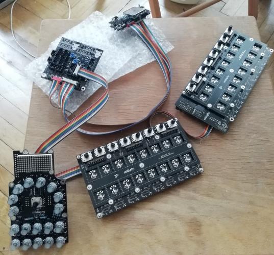
Another build, another problem :).
Finished the USB and Ucore PCB - soldering, mounted the Waveshare PCB and my PC wont find any Midi-Device. When Waveshare-PCB is connected directly without uCore it is detected (with power set to USB mode). However, when mounted to the uCore all i get is a lighting "PRW LED" but no Midi Connection found. I already restarted the Software and my Computer to "refresh" but that didnt help either. Here are some picks of my work so far. Maybe someone has an idea at what i should take a closer look (obviously Pin-headers should be soldered correctly and cable shouldnt have a short). Sorry for the bad lighting on the pictures I will try to provide better ones if needed.
Thanks in advance!
Alex
Ps: I cannot upload pictures directly to the forum (error -200). Is there a max file size?


Troubleshooting midiphy SEQ v4+
in MIDIbox SEQ
Posted · Edited by knochenfabrik
Thank you again for the fast response. I tried to reflow some pins and get rid of short where they seemed to be possible.
Status Quo: Japcb + Les Mec LH work fine together but when Reconnected all the PCBs and loaded SEQ_L - with both les mecs installed all the encoders still dont work (no turns and press on all of the encoders on both boards) - when i press switches on JApcb i get the following in console:
"[10389.729] load seq_l
[10390.157] [MBNG_LCD] no response from CLCD #1.1
[10390.157] [MBNG_LCD] no response from CLCD #2.1
[10390.157] [MBNG_FILE_C] Event Pool Number of Items: 348
[10390.157] [MBNG_FILE_C] Event Pool Allocation: 12250 of 65536 bytes (18%)
[10390.178] Patch 'seq_l' loaded from SD Card!
[10390.184] [MBNG_FILE_R] /seq_l.NGR (optional run script) not found
[10396.484] set debug on
[10396.655] Debug mode turned on
[10402.023] MBNG_MATRIX_NotifyToggle(2, 34, 0)
[10402.023] MBNG_DIN_NotifyToggle(3034, 0)
[10402.023] [EVENT] id=BUTTON:3034 hw_id=BUTTON:3034 bank=0 fwd_id=LED:3034 type=NoteOn value=0 label=
[10402.023] MBNG_DOUT_NotifyReceivedValue(3034, 127)
[10402.023] MBNG_MATRIX_DOUT_NotifyReceivedValue(3, 34, 127)
[10402.026] MBNG_MATRIX_NotifyToggle(2, 50, 0)
[10402.026] MBNG_DIN_NotifyToggle(3050, 0)
"
Can i assume that failure must be on the Lemec-board (RH)?
Additional question: is it possible to progress without the lemec (RH)? - install and test the OLED, MIDI8 etc.?