

j4ustin
-
Posts
15 -
Joined
-
Last visited
-
Days Won
2
Content Type
Profiles
Forums
Blogs
Gallery
Posts posted by j4ustin
-
-
Noticed some weird behavior today while sending a midi clock out via midi port 3 to a Norns device. The clock on Norns was showing a clock speed 3x the amount set by the loopa. When I turn off MCLK DIN OUT for all but one of the outputs it sets the clock correctly on the Norns. Perhaps it is sending 4x the midi clock signals. Possibly related is that the Loopa sends a midi clock out of port 3 even if that output turned off in the settings. IE: I currently have all MCLK DIN OUT set to OUT1 only, but my Norns is getting the correct clock settings even though it's attached to PORT 3.
The USB clock out works OK as I am syncing Ableton via USB MIDI clock.
-
Thanks again for the help, been learning the device today. Think it could become the heart of a live setup. Cheers guys!
-
 1
1
-
-
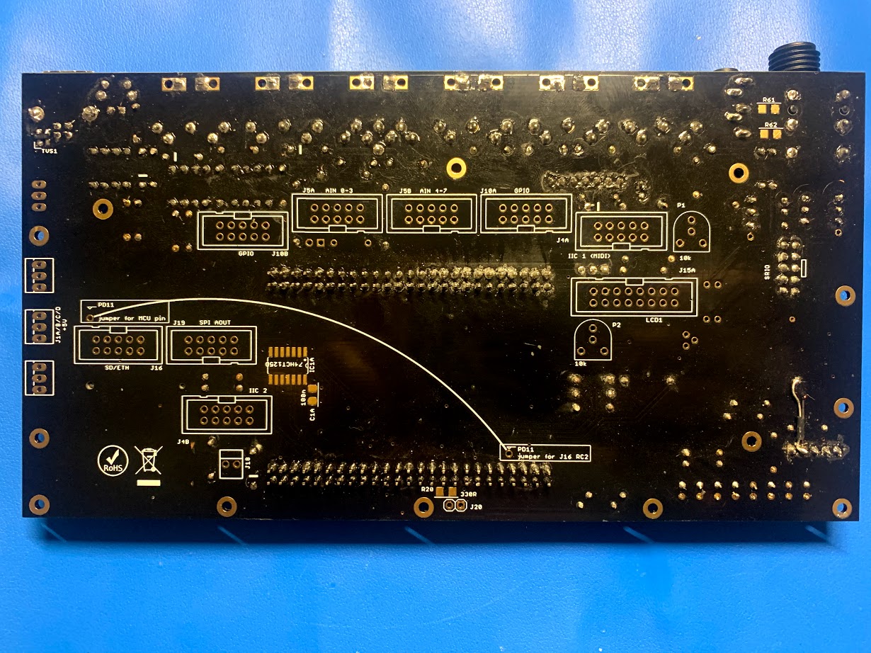
Got it! That picture you posted had a busted trace as well. Must have cut that one when I was chopping off the plastic pieces that hold the pins together. Everything is working great now! Thanks for all your help @latigid on and @Hawkeye. Can't wait to box this thing up and get playing!
-
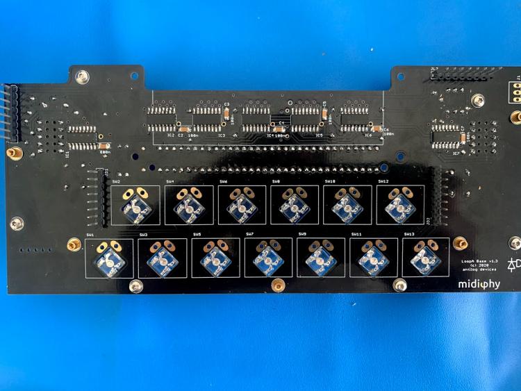
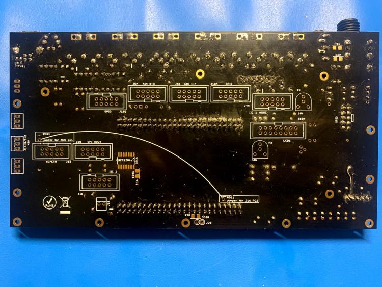
Made a critical mistake during the build and missed soldering in the sockets on the core pcb and, instead, soldered in the actual pins from the top board. This led to having to remove the pins via de-soldering and I knicked (likely with my cutting tool) the board just above j15C header causing the issue. That was the only de-soldering I've had to do on the board at all, should have paid closer attention to the instructions at the beginning of the video. Didn't spot this broken trace as it was kind of hidden by the socket. I've double checked all the sockets for any other knicks that may have happened.
I've tested for continuity from the bottom of base pcb socket pins to the connected plate pcb pins on top and there is connectivity between all the pins. I'll double check for any shorts between them. I'll go back through and fix the soldering on those pins
This is the resistor network I've put in place on the plate PCB: https://www.mouser.com/ProductDetail/652-4816P-T2LF-10K. I'm sure aligned the dot correctly with what is on the silkscreen, and have verified by re-watching the video at that point to ensure I had the placement correct.
-
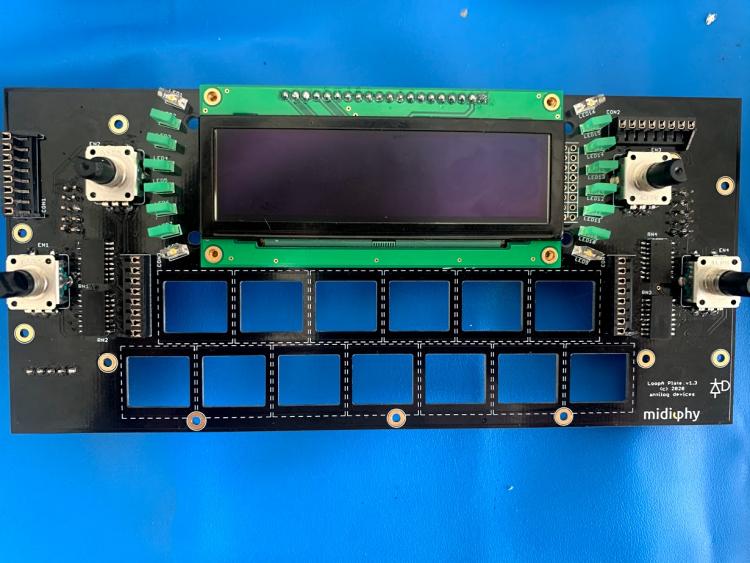
None of my buttons or encoders are registering. I validated that all of the headers are making contact from the bottom of the board to the top, and i can trigger a button press by bridging the top two pins on the j9a header so I know that the button presses can work. Nothing from the encoders though.
I'm going to keep checking where the connections could be failing. Any pointers here would be excellent, feel like I'm one step away from this thing wrapping up.
-
Yeah! Feeling better now. Any tips on where I could look to fix encoder presses and button presses? None of those are registering with the boards. I am seeing the led's all lighting up for both the side of the screen and the buttons. I also see the animation for LoopA Testmode
-
Got it! Turns out i cut a trace between the j15c header 4 and the pc9 header on the waveshare. Must have missed that test when I was going over it earlier. Still have the encoder issues, so that's next, but feeling better about this though.
Going to have to look closer to ensure I didn't cut any other traces on the board which may be causing the encoder / button issues.
-
1
-
-
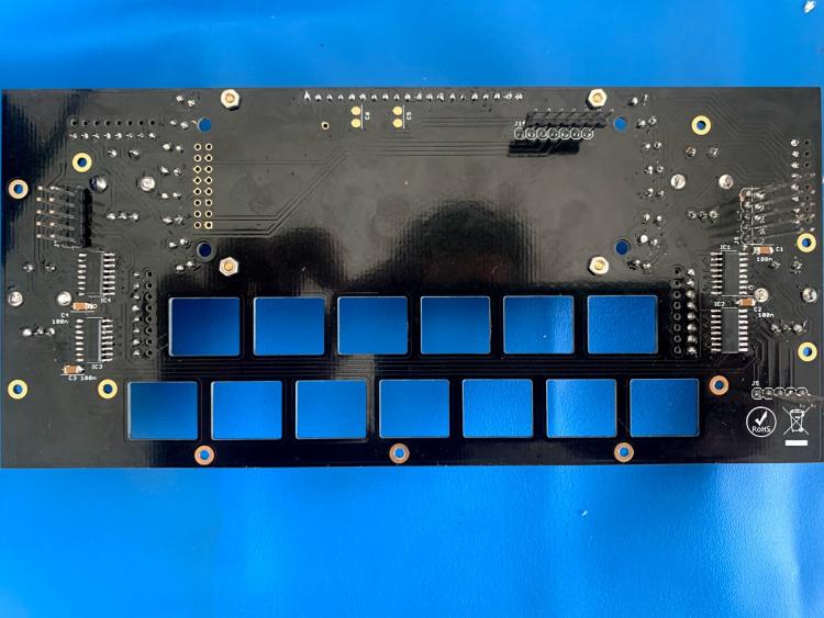
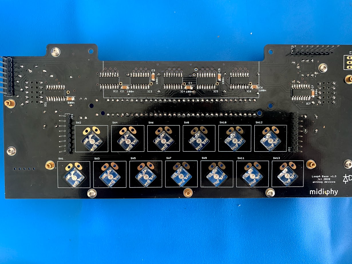
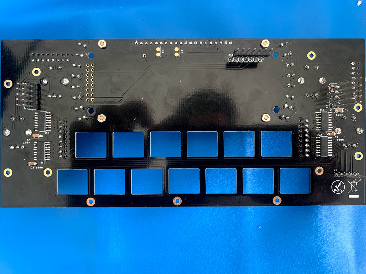
Here are the other pcb's. These came out cleaner than the base. Maybe I missed something, but I've been through the video feels like twice now.

-
Just now, latigid on said:
Hmm, did you try reflowing the joints? How is the unit being powered? Is the LoopA firmware loaded? Are you running in test mode (no SD card)?
You could check the above-mentioned pins for shorts to 0V/3v3 or even to each other, so check a) adjacent pins on the J15C header and b) pins on the waveshare breakout,
Happy to take a look at the soldering of the other boards. You can also load MB_NG and check if your DIN is working as expected from MIOS Studio (set debug on).
I reflowed every joint and checked the soldering on pretty much every header.
im powering with a usb into my computer. Have tried with 2 usb cables and a usb wall jack as well.
validated the loopa firmware is in there. Can see the io options in my daw with the loopa plugged in.
it is in test mode. I’m seeing the light cycling as in the video test mode. The side screen leds all light up and the button leds all cycle through correctly as well.
I’ll check for shorts and the din next.
-
I checked for continuity between the J15C and the waveshare pins then all the way to the display from the j15c on the bottom of the board. All of the connections are being made correctly and the reset is showing 3.3v as well as the 3.3v header on the display itself. There is continuity between the Net NS9 and the IC2 header 15 pin as well.
Another symptom I noticed that could be related to the screen is that my pots and buttons are only sometimes triggering the lights as registering input when testing with a jumper on the buttons or pushing down the encoders. That behavior makes me think that maybe the two might be related since the connectivity between the screen and the waveshare seems intact.
-
Thanks @latigid on. I'll look into all these pointers and will report back.
-
Sure. Thanks again for the help. Also, sorry if some of this is messy, I'm still getting my feet wet with larger scale projects.
-
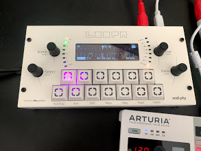
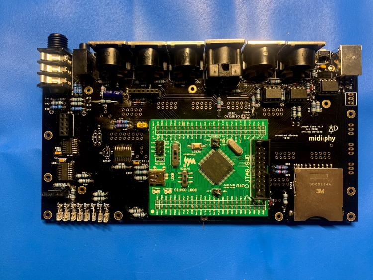
Hey all, I've gotten most of the loopa put together over the past week, but my screen will not start.
The loopa boots up ok and enters test mode. I can trigger the button presses and am seeing responses from the side leds. There does seem to be an issue with the pots as when I push them in they don't register the same as the buttons. Not sure where to look to try and debug this further, any help is appreciated.


LoopA V2 Introduction, Features & Support Thread
in MIDIbox User Projects
Posted
Hey @Hawkeye,
Figured it out thanks to your advice! I have an echo going from my Launchpad pro -> Norns. As you pointed out in (c) this is because I have a router turned on that passes Input 1 (my launchpad) out to the Norns. The clock signal being sent from the Loopa to the Launchpad is passing through and sent again to the Norns, and when the clock output for Norns is turned on I'm seeing the multiplication.
Thanks for the help!