

Duggle
-
Posts
992 -
Joined
-
Last visited
-
Days Won
5
Content Type
Profiles
Forums
Blogs
Gallery
Everything posted by Duggle
-
I'm not actually sure about this.... I'm very much in a learning mode with SEQV4. I've come to it with only the V4lite as background (I think the capabilities of the SEQV4 are brilliant, btw!) I'm looking at my rig and thinking about how to make the elements work together. I'm not sure what you mean by "phrase"...if its a different starting point in the song.. that may be useful but it does reduce the "address space" of the song selection method. Focusing on my current needs, the RC-50 has 99 patches (song slots) which would map well to SEQ songs in a 1:1 way, I guess.
-
My set-up has an RC-50 Looper feeding a midi clock into MIDI IN2 of my SEQV4. The SEQV4 responds to start/stop, sync very nicely. It makes sense therefore to have song selection controlled from the RC-50 panel also. The RC-50 will send out a program change when it's patch is changed and it has a table to determine which program number gets sent. Is there a way to make this select the current song in the SEQV4?
-
That's great to know! For large and performance critical stuff I am, and will, use LPC17 for obvious reasons. Its nice to have the possibility of smaller, cheap, and simple processor where appropriate.
-
Great TK, I assume what wasn't working (reliably) now is? If I'm correct regarding the signals going to the SR's, the RS line is non critical as it's transition latches the register data to the output pins (in the case of DOUT), and samples the input pins into the register (in the case of DIN). If there is bounce on this line it does not change anything. Does this mean no source code for STM32, or no documentation? It's just that I've been doing an additional side project with what I'm calling a "MiniCore" . It involves the STM32 chip soldered to a LQFP SMD adaptor board. It's small, very cheap $0.90, plus $6.90 for the STM32F103RET6. Its best suited for projects where you don't necessarily need heaps of I/O options connected to the core. Anyhow, it works great with MIOS32 so I guess that is enough (heaps,actually!!!). It will come to light when I post details of my novel take on BLM (coming soon!). If NG can be used on this MiniCore platform it would be a bonus. Oh yeah, I have a method of soldering the LQFP that I recon even the greenest newbie could successfully do! (It involves solder, iron, wick, and flux paste).
-
Yes, and also (more importantly) pin 12 which is the clock. The clock is distributed to all SR's in the chain (the data line is re-transmitted between each SR, so less prone to integrity problems, RST line won't cause problems either ), so it's much longer, more prone to problems such as ringing, which can introduce extra transitions and corrupt data in the SR's.
-
Normally the signal integrity potential problems can be solved/prevented by: Good layout and wiring (e.g wire clock in a point to point (not star) manner, reduce the area of the loop formed by the signal path and it's ground return,etc.)drivers and termination. I notice the LPC17 core has a 541 driver. That's good, but I predict that potential problems may be caused by the fast edge transitions onto the transmission line of DIN/DOUT connections. The fix is very simple: a (typical) 100 Ohm resistor in series with the signals at the output of the driver. This helps in a couple of ways: it slows down the edge transitions by enough to reduce excitation of resonant modes(ringing). It also provides a closer match of driver to line impedance resulting reflections getting absorbed rather than reflected -> reduced or eliminated line ringing.The STM32 core has an open drain and 220R pullup driving the line. The effect of this can be seen pictured in this article The rising edge (driven by the 220R pullup) is fine, but the falling edge ( driven by the port pin drain) shows the signs of ringing. Since I wrote the blog article, I've discovered the best termination that fixes this is a diode in parallel with the series termination resistor at the driver source. In other words a 220R resistor in parallel with a signal diode (anode towards the driver, not the line). The affect of this is that a high is driven onto the line by the 220R pullup (passing through the diode) and a low is driven through the 220R series termination resistor.Its a bit late to change/improve the PCB layout of 16LED ring PCB, but I think the way to drive a large string of these modules is with the termination schemes I've just outlined. To guide newbies, it may be possible to explicitly state the conditions where it is possible to exceed the 16SR limit. That is, you can use nn of module yy with xx cm of standard ribbon, terminated in such and such way. Anyhow it's a subject area I can see myself involved with a lot in the future. I'm interested in taking the keyboard display in the direction of 6 (or so) octaves of RGB. To get good colour resolution and variable brightness and invisible flicker, It may be necessary to address the DOUT chain with higher frequency updates (even faster clock rate, if it be necessary) so I'll be headlong into signal integrity issues, sooner or later!
-
Some questions: How about LCD display of dynamic text as in patch name(s) contained within a received Sysex message?Previously the 16SR limit was advised rather than forced. I have a project (in development, still after ~2 years!) that uses long chains, a linear LED display for keyboards, not so suited to matrix wiring. I assume it will still be possible to use MIOS32 functions to address long(er) chains of SR's? (when integrated into a NG framework device ,that is)thanks!
-
The mod works brilliantly! I've documented the hardware and software changes in this blog article: If anything is unclear let me know!
-
From the album: Duggle
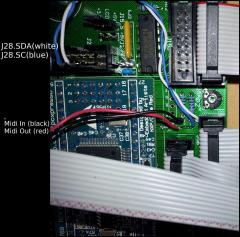
Wiring of MIDI Port 3 -
From the album: Duggle
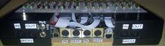
Back of SEQV4L modified to have 4 MIDI ports -
Abstract This article documents the hardware and software mods to provide 2 extra (4 total) Midi I/O ports on the MB SEQ4L. The added ports use the onboard UARTs (2,3) of the LPC MIOS32 core. The underlying sequencer code supports these ports (MIDI 3 and 4), but in the case of MIDI 3, the pins used, need to be replaced as they are( were) used to drive LED matrix columns. I chose J28 to provide these LED column driver pins, unfortunately they are part of the CV output (which I don't want) which has to be disabled in the software. Introduction The Midi Router functionality of the MB SEQV4 (Lite and "Full" versions) allows complex and well integrated MIDI interconnection of Synths and devices. The motivation in my case was to have Sysex Librarian and PC host synth patch design avaiable using the 4 available USB MIDI ports. Suffice it to say that having an extra 2 midi ports allows me to have RC50 Looper, MBSEQ, keyboards, and 2 Virus synths all talking and editable simultaneously from my PC. Perhaps the details should go in a separate blog article. Hardware Mods MIDI I/O Port 4 This one is straight forward as port J4B is free. Simply connect a 2pin header receptacle: J4B.SC->Midi In J4B.SD->Midi Out Ive used a GM5 PCB for MIDI sockets, opto, etc. but can use a standard circuit built on vero board. Just copy the circuit from a core. MID I/O Port 3 This one is a little more involved as the pins that have the UART functionality are on J15 which is used to drive the LED matrix columns on the SEQV4L. I've chosen J28.0 to replace J5B.6 (column driver) and J28.1 to replace J5B.7 (column driver) Core pin J5B.6->Midi IN (black wire in picture) Core pin J5B.7->Midi OUT (red wire in picture) J28.SDA->J5B.6 (connector) (white wire in picture) J28.SC->J5B.7 (connecor) (blue wire in picture) (above) MIDI port 3 wiring NOTE TRACKS ARE CUT between black and white and between red and blue!!!! Software Mods \trunk\apps\sequencers\midibox_seq_v4_lite\mios32\mios_32_config.h This enables the extra midi ports in the firmware include the following lines (comment out conflicting #defines) #define SEQ4VL_FOUR_MIDI_PORTS /*switch used elsewhere to compile this mod*/ #define MIOS32_USB_MIDI_NUM_PORTS 4 /*use with bootloader 1.010 or later for proper multiport usb */ #define MIOS32_UART_NUM 4 \trunk\modules\blm_cheapo\blm_cheapo.c This is where the column drivers port pins are initialised, including the replacement pins of J28 replace for(pin=0; pin<8; ++pin) MIOS32_BOARD_J5_PinInit(pin, MIOS32_BOARD_PIN_MODE_OUTPUT_PP); with // initialize all pins of J5A and J5B as outputs in Push-Pull Mode //***dug*** 6 and 7 are wired to MIDI IN/OUT3 //these signals are generated by J28.SDA and J28.SC, 0, and 1 respectively #ifdef SEQ4VL_FOUR_MIDI_PORTS for(pin=0; pin<6; ++pin) MIOS32_BOARD_J5_PinInit(pin, MIOS32_BOARD_PIN_MODE_OUTPUT_PP); MIOS32_BOARD_J28_PinInit(0, MIOS32_BOARD_PIN_MODE_OUTPUT_PP); MIOS32_BOARD_J28_PinInit(1, MIOS32_BOARD_PIN_MODE_OUTPUT_PP); #else for(pin=0; pin<8; ++pin) MIOS32_BOARD_J5_PinInit(pin, MIOS32_BOARD_PIN_MODE_OUTPUT_PP); #endif insert #ifdef SEQ4VL_FOUR_MIDI_PORTS //J5 bits 6 and 7 are not initialised for GPIO so have no effect MIOS32_BOARD_J28_Set(led_row[selected_row]>>6);//put J5 6,7 into J28 0,1 #endif after MIOS32_BOARD_J5_Set(led_row[selected_row]); in s32 BLM_CHEAPO_PrepareCol(void) This drives the replacement pins of J28 of the LED matrix column. \trunk\apps\sequencers\midibox_seq_v4_lite\core\seq_file_hw.c (about line 860) comment out thus: #elif defined(MIOS32_FAMILY_LPC17xx) for(i=0; i<4; ++i) { // MIOS32_BOARD_J28_PinInit(i, pin_mode); // MIOS32_BOARD_J28_PinSet(i, 0); } #else The remaining changes are to stop the J28 now LED matrix pins being driven by the old CV code: \trunk\apps\sequencers\midibox_seq_v4\core\seq_cv.c line 70 in SEQ_CV_Init() change #elif defined(MIOS32_FAMILY_LPC17xx) for(i=0; i<4; ++i) MIOS32_BOARD_J28_PinInit(i, MIOS32_BOARD_PIN_MODE_INPUT_PD); #else to #elif defined(MIOS32_FAMILY_LPC17xx) for(i=2; i<4; ++i) MIOS32_BOARD_J28_PinInit(i, MIOS32_BOARD_PIN_MODE_INPUT_PD); #else comment out first 3 calls to MIOS32_BOARD_J28_PinSet in s32 SEQ_CV_Update(void) thus: #if defined(MIOS32_FAMILY_STM32F10x) MIOS32_BOARD_J5_PinSet(9, start_stop); #elif defined(MIOS32_FAMILY_LPC17xx) //MIOS32_BOARD_J28_PinSet(1, start_stop); ***HERE*** #else # warning "please adapt for this MIOS32_FAMILY" #endif } // DIN Sync Pulse at J5C.A8 if( seq_core_din_sync_pulse_ctr > 1 ) { #if defined(MIOS32_FAMILY_STM32F10x) MIOS32_BOARD_J5_PinSet(8, 1); #elif defined(MIOS32_FAMILY_LPC17xx) // MIOS32_BOARD_J28_PinSet(0, 1); ***HERE*** #else # warning "please adapt for this MIOS32_FAMILY" #endif --seq_core_din_sync_pulse_ctr; } else if( seq_core_din_sync_pulse_ctr == 1 ) { #if defined(MIOS32_FAMILY_STM32F10x) MIOS32_BOARD_J5_PinSet(8, 0); #elif defined(MIOS32_FAMILY_LPC17xx) // MIOS32_BOARD_J28_PinSet(0, 0); ***AND HERE*** #else # warning "please adapt for this MIOS32_FAMILY" #endif Conclusion That's it!!
-
Looks amazing! Has any thought gone into the possibility of parameter feedback? The example I'm thinking of is a synth control panel where all parameters are encoded as CC and note Aftertouch messages. Obviously when an encoder or button is pressed the value is changed, sent and displayed. Now if the value is received, the idea is the display and state of the control is updated to reflect this. In the case of the Access Virus, a simple dump request message would result in the the whole midibox being updated with the current patches values for every parameter, ready for modification. Also, it would keep the midibox "in sync" with data changed from the front panel controls of the synth.
-
Thanks for posting the solution. I remember having the exact same problem some time ago but could not remember what I had done to fix it!
-
Beta Test: MIOS32 Bootloader v1.009 could solve USB issues under Windows
Duggle replied to TK.'s topic in MIDIbox SEQ
Hadn't noticed a problem (yet), but I suppose with this driver we get the same great host side performance as the GM5 chip on our MIOS32 Midibox(s)? -
I'm looking at the manual Record Page. Its a little difficult for me to grasp the precise organisation of these settings as my SEQV4 is not quite assembled. Does the Trk. field change with the realtime song position or is there separate settings possible for each track (I suppose not) ? It would seem that I need to do 2 setting changes together on the fly to achieve what I've outlined: record source channel and track output channel (1,1->2,2->1,1 etc) Anyhow, if you add the capability I'll test it and likely use it a lot.
-
I'm in the final stages of assembly of my SEQV4(heavy). I'm passing the Lite to the drummer I play with (we tried it with drum/percussion loop record, fantastic!) So with the SEQV4 is it possible to have the scenario I outlined (without needing to modify firmware): keyboard 1, playing synth 1, on channel 1 keyboard 2 (merged with kb1 to midi in 1), playing synth 2, on channel 2 Then by simply changing one setting, change which gets recorded?
-
I thought I would only need to buffer the first 6 or so bytes of the sysex stream, then (if ID match) put them to the output queue as well as the remaining bytes (one by one) of the message. I'll look at this. But how to change the midi channel of the recorded events? I'm not sure how this works. My ideal (I think) would be each keyboard on different channel (merged) controlling each synth, then to choose which keyb/synth combo gets recorded with the seq midi channel selector? Should this work? Works!
-
Beta Test: MIOS32 Bootloader v1.009 could solve USB issues under Windows
Duggle replied to TK.'s topic in MIDIbox SEQ
Updated the bootloader and reflashed app (SEQV4L) without issue. Previous issues of Sysex corruption involving multiclient USB to synths (Win7x64) are solved! I've used the opportunity to enable fastboot and USB name. Nice! -
Yes, you definitely do not want any Sysex messages duplicated on the same port. And also I suppose it is best to pass Sysex even if channel filtering is used. To help me understand: I could buffer and parse the bytes passed to SEQ_MIDI_ROUTER_ReceiveSysEx , looking for a device ID (assuming I'm synchronised with the start of each sysex message) and when I've established the device ID put the buffer to an event queue of the target port, and set up to send the remaining bytes of the Sysex message to the target port? I need to focus on why I started thinking about this: I have a control surface on one of my keyboards which is routed to one synth (Virus C), and I would like to assign knobs to control another synth (virus B) which is connected to a second keyboard. I should re-analyse the connectivity options because it occurs to me that if I simply merge the keyboards to a common midi wire, I can address each synth with midi channels and sysex to each synth with device id's. Then there is the question of interaction with SEQV4L: It will record the selected midi channel and simply pass through others? So far I've been using the sequencer with channel set to 1. If set to a different channel does it play back on the same channel? I'm thinking it would be great to record material on either synth by switching channel. Also worth mentioning, I'm nearly completed building a SEQV4 full CS which I will use in place of the Lite. Thanks!
-
I'm using the SEQV4L USB midi port(s) on the sequencer/keyboard/synth rig with a laptop running winXP. Works great! Where we have set router nn SRC xx DST yy Does this usually mean that node nn will connect events on midi channel xx from SRC port and force them to channel yy on DST port? If so, is there any way of selectively routing doing a similar thing with Sysex messages? (I'm guessing not as each manufacturer has a different way of determining a destination device for sysex e.g Access Virus has a device ID field. This would require a specific router handler for Access Virus type sysex. If I really wanted this feature is the way to implement it at all straight forward?
-
Right!!!
-
The concept involves new and improved configurations, new capabilities. It will use existing LPC17 core plus existing MBHP modules. As in the past, folks will sometimes combine the required elements for a particular configuration or project into a single PCB. This would be considered new hardware I guess.
-
Thanks, TK. I'm not too much worried about performance as the OSC segment would only be handling patch editing/librarian (not playing/sequencing as such). I think I'll have to wait until a windows user creates a binary or at least makefile for a windows build (it's a bit outside my knowledge/interest area). I'll try other connectivity options such as midi mergers between the keyboard(s) and CPU midi out port(s) and synth(s). There is nothing stopping me, this way and I know it all works well. The multi client capability of the the GM5 drivers is really handy too!
-
I modified the firmware to provide one USB midi port only. It sometimes exhibits the same problem with sysex response from the synth. Therefor there is still hope with multiport if I can figure out what is going wrong! In the meantime I need to find a setup that JUST WORKS. I will resort to h/w midi mergers if I have to. Is there such a thing as OSC midi bridge drivers? Is OSC a possible working solution in such a situation?
-
I'm also not TK, but would think that seeing the functionality of the KB interface is working (and well by the looks) that the interface is reasonably modular and can be included with various midibox configurations with different benefits and trade-offs. I get my 2 Keybeds (61 keys) from the local Doepfer agent next week. Cant wait to build my custom dual manual keyboard!