
Lorcan
-
Posts
83 -
Joined
-
Last visited
Content Type
Profiles
Forums
Blogs
Gallery
Posts posted by Lorcan
-
-
I have used Schaeffer in the past, a bit pricey but great workmanship.
I am going to try frontpanels.de for my next panel, they seem cheaper and the examples inspire confidence.
-
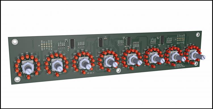
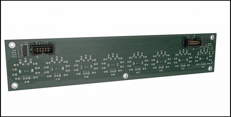
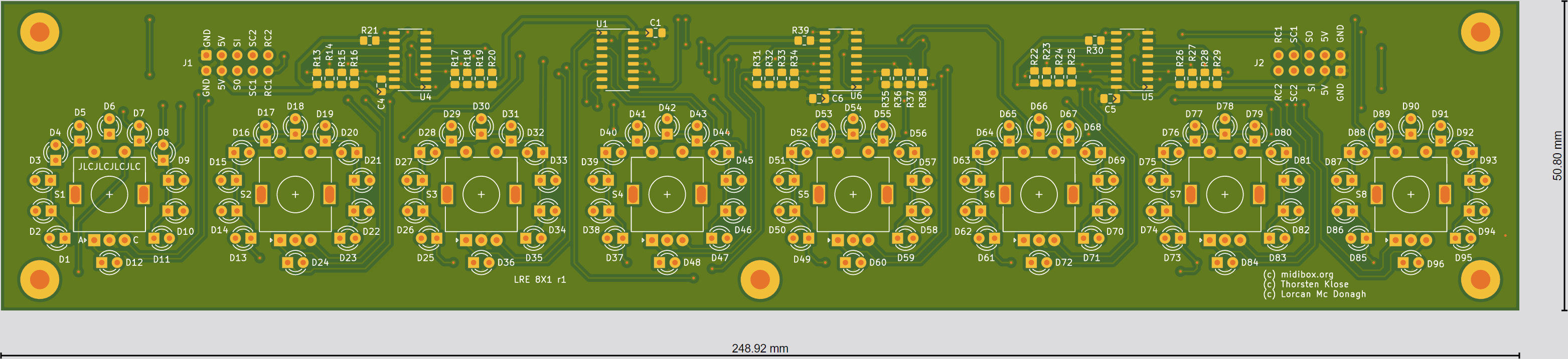
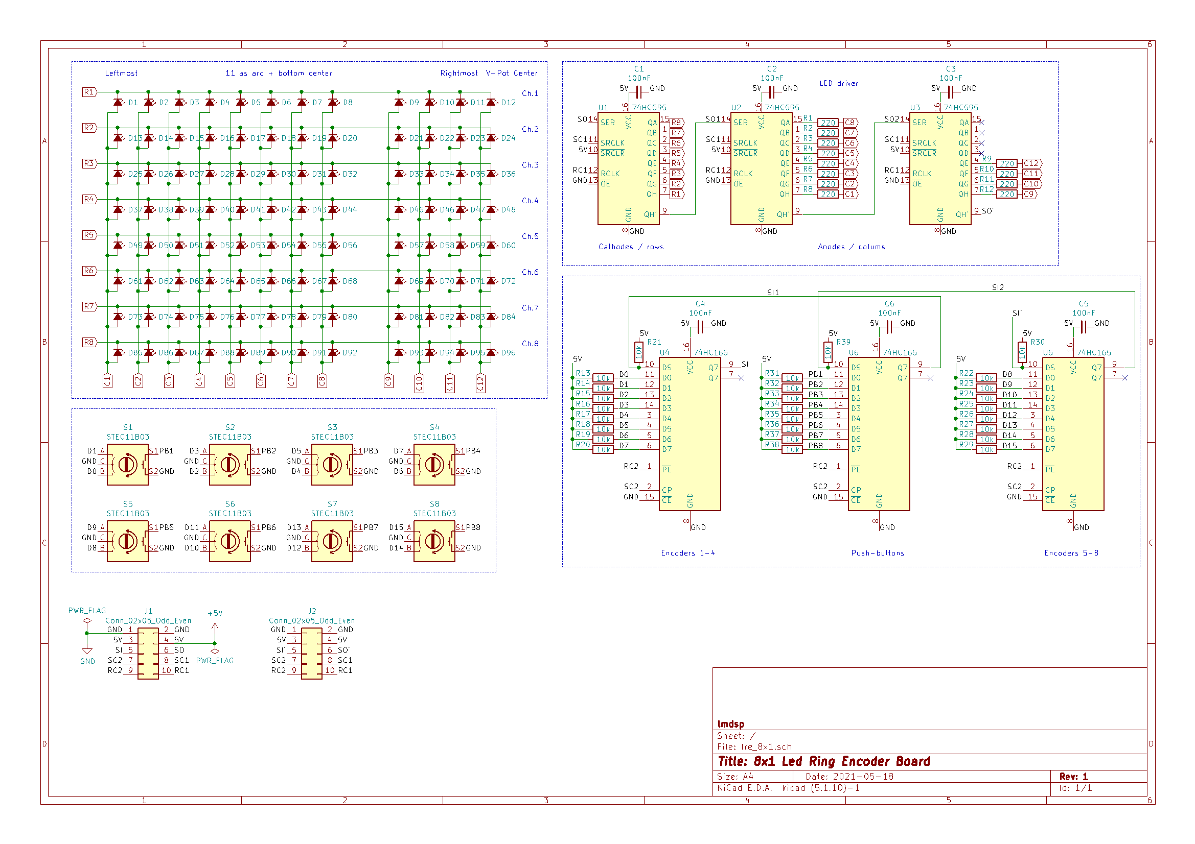
Hi,
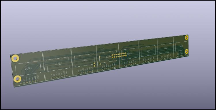
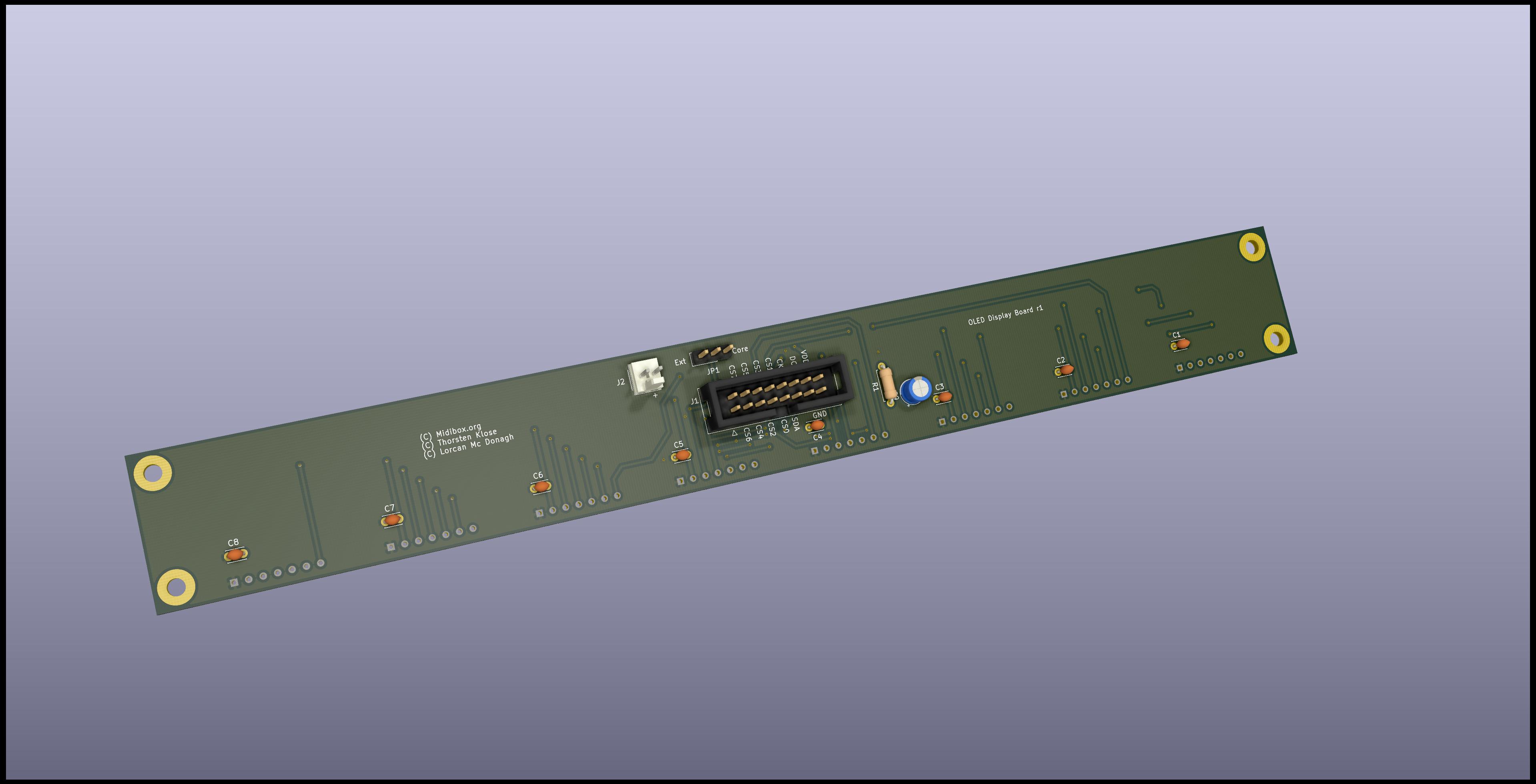
continuing on my MCU clone design, here is a board I designed to hold 8 encoders, LED rings and integrated DIN / DOUT modules.
To keep it compact I used SMD parts (1.2" spacing between encoders), but that shouldn't generally be a problem for someone with a little bit of experience to hand solder (SO16 / 0805).
Please tell me if you spot any mistakes or potential problems !


-
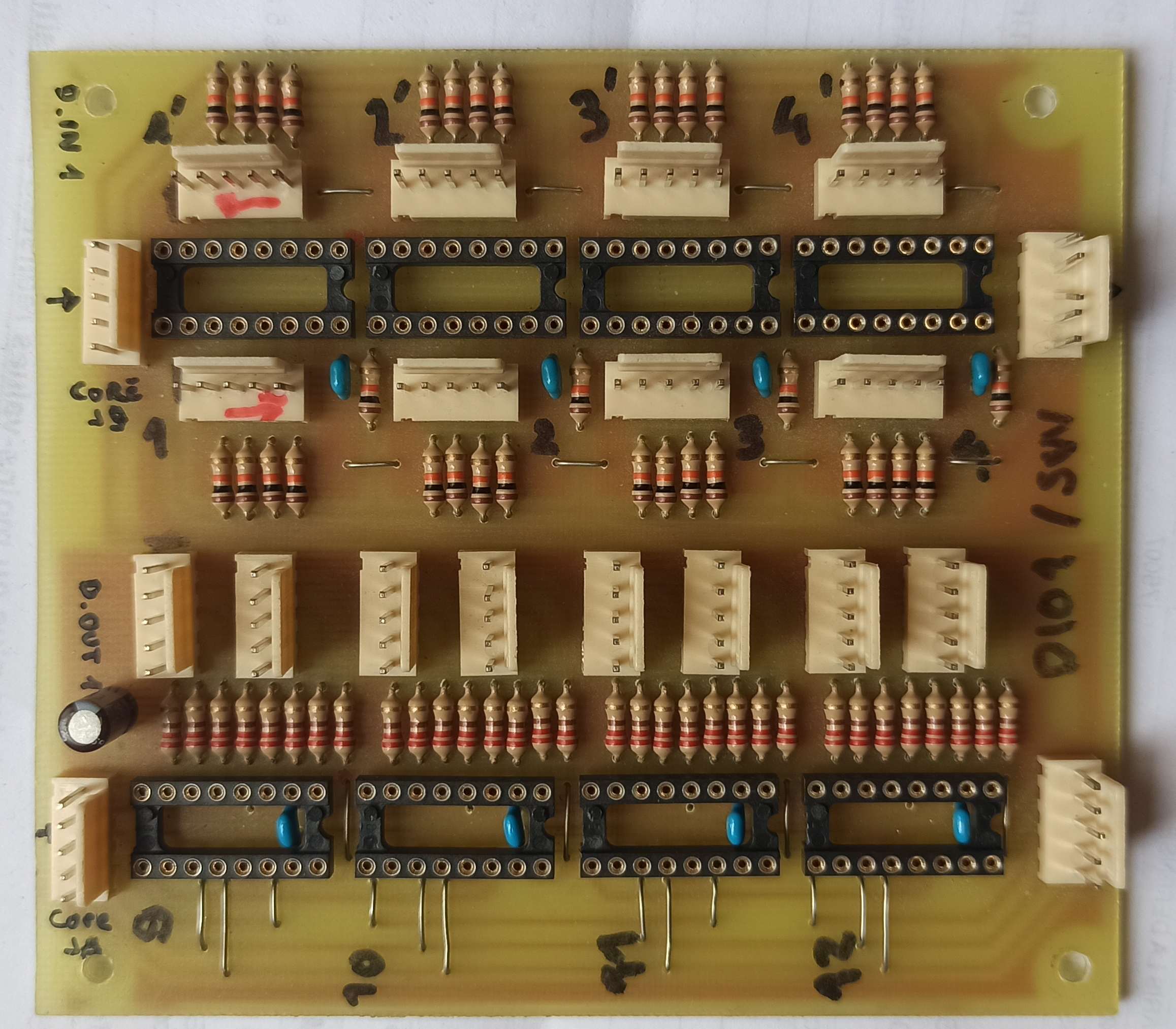
By the way I forgot I had this old DINx4/DOUTx4 assembled combined board laying around.
It's the older r4 version not the latest r5 with box connectors. I can sell it to you for a few euros if you want.

-
4 hours ago, Meadow said:
Sounds like a good option, since the modules are still out of stock on modular addict.
I could find a .brd file on the ucapps Page.
There's only the note I should ask SmashTV.
But I think they went out of business?
I couldn't find any information on them
Can I get the layout data anywhere else?
Aisler need the .brd file, am I right?I believe ModularAddict took over from SmashTV, so perhaps you could try asking him.
But it's his work and how he makes his living, so that would be a very generous offer from him.
Aisler take Eagle, KiCAD and other files.
As I said in a previous post it's really not very complicated to make a PCB design from a schematic.
Plus you'll learn a skill which will be useful for other future projects. -
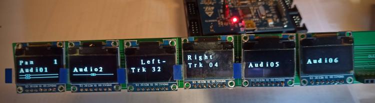
What a nice feeling to find out it's working !
-
29 minutes ago, Phatline said:
try a temporar reset line for that display... (could be done by making a adapter cable between OLED and PCB ...while you cut the Reset Wire, and feed there the 1K 10uF thing in....) - and see what happens
else i would try to set X8 to X9 (only for testing - not that is right - X8 is right...)
then i would try to set the LCD Type to SSD_1306 Rotated (not that is right...)
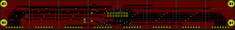
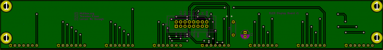
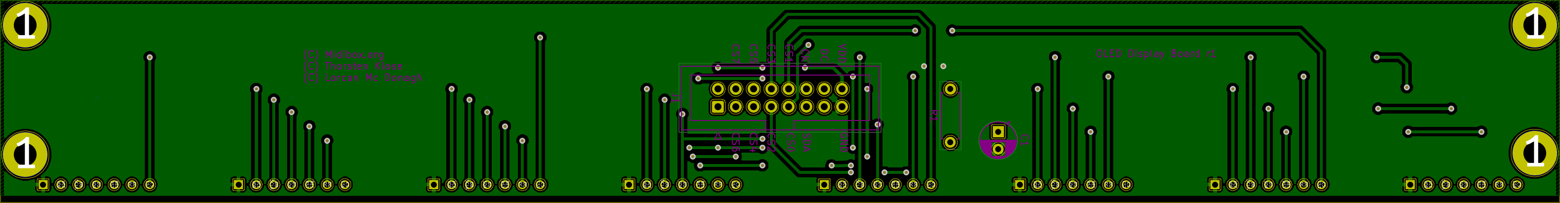
then i would post the board-file-picture (i cant see anything on your Separated Top/Buttom Pictures...i become eye and brain-cancer)
Thanks, I've tried all of the above already. I've put the OLED on a breadboard too and tried all CSx lines, they all work except CS7.
Then I checked the motherboards and noticed that a few solder joints were less than perfect.
Turns out they're all GND connections and that the pads don't have thermal relief, which isn't great.
I also swapped out the U74HC595AC I got from Reichelt (made by Unisonic Technologies, never heard of them) for 74HC595AC by ST I had laying around, they seem less susceptible to noise.
Now everything looks much better ! There's just an occasional glitch on a few pixels on one board which I'll investigate later.
-
3 minutes ago, Phatline said:
you removed all Solder-Flux? (Aceton...) (i always have problems with that low-impedance Shit (<1K! between to pins because of some flux...)
by swapping cores you mean the whole Motherboard and Discovery? if only discovery > try to replace that 595er...
send a picture of that "garbled" --- if it looks like noise then you may not set the Displays right (bootloader-app > help > displays num x and y.... maybe one to less?)
else post a board picture (with top and buttom layer in one....) may there is something you dont see....
Yes I thoroughly cleaned all boards with isopropyl, thanks.
I have 2 complete motherboards + discovery as I plan to build a MCU + a MCU XT.
I double checked the bootloader, eveything is fine: SSD_1306 x:8, y:1
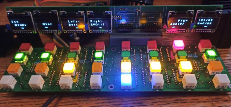
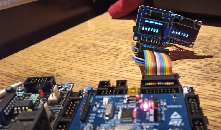
This is what it looks like: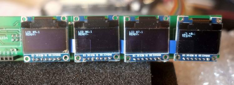
-
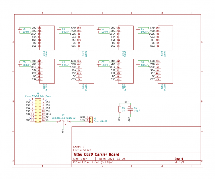
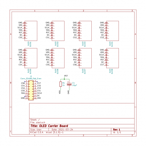
Looking at the core schematic, I see CS7 is connected to both Q7 of the 74HC595 and PD7 of the STM32F4, whereas CS0-CS6 are connected only to Q0-Q6 of the 74HC595.
If PD7 is also an output pin, I wonder if PD7/Q7 could be interfering with eachother ? -
Found a problem: the 8th display is always garbled.
I've tried swapping the OLED's, adding 100nF decoupling caps, stuffing only one, swapping cores, using a separate breadboard with only CS7, 3.3/5V, haven't managed to fix it yet :(
I hope the external 3.3V supply will get rid of this ...
-
Thanks, I'll incorporate this idea when I'm done with all the rest.
I don't think I'll do it for the LEDs though, I've yet to see one of those fail on me. These things are incredibly enduring, provided you use reasonable currents.
For the 3.3V, I'll be using this 3€ DC/DC part, it hardly dissipates any heat unlike linear regulators. -
1 hour ago, Phatline said:
really hot?
i use 9x OLED-LCDs and a 2x16x16 LED matrix on one core - have no problems here - so far... but i also implemented a "screensaver" in my app, that turn of all UI when nothing is touched for 4 minutes... (thought of dead Oleds and dark BLM-Leds . in far future...)
It's not that hot, but I only have 6 screens connected atm.
The regulator on the core is rated at 100mA absolute max and it's a tiny SOT23 part, so it could become a problem if people use fonts with lots of lit pixels.
This page quotes as much as 40mA consumption in certain scenarios !
And for general reliability it's better to keep things running cool ;)
The screensaver is a great idea, the life of these things is a few years at most and I'd prefer not to replace them that often. May I ask how you implemented that ?
-
First test, everything seems in order !
The 3.3V LDO on the core board is a little hot, I'll probably use external power for this.
-
I don't know of any other seller.
Why don't you order it for manufacturing yourself e.g at Aisler ?It's a simple design and you should be able to route it in KiCAD easily.
For a 6x11 cm PCB, it would cost you ~14€ vs 21$ at modular addict. The shipping will probably cheaper/faster as Aisler is in Germany too !
-
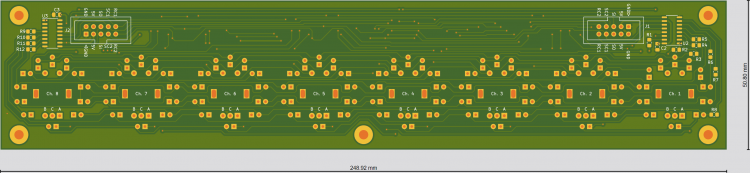
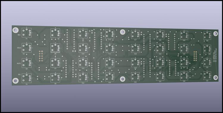
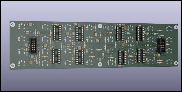
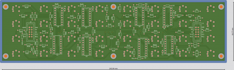
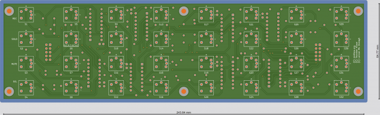
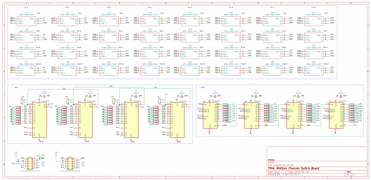
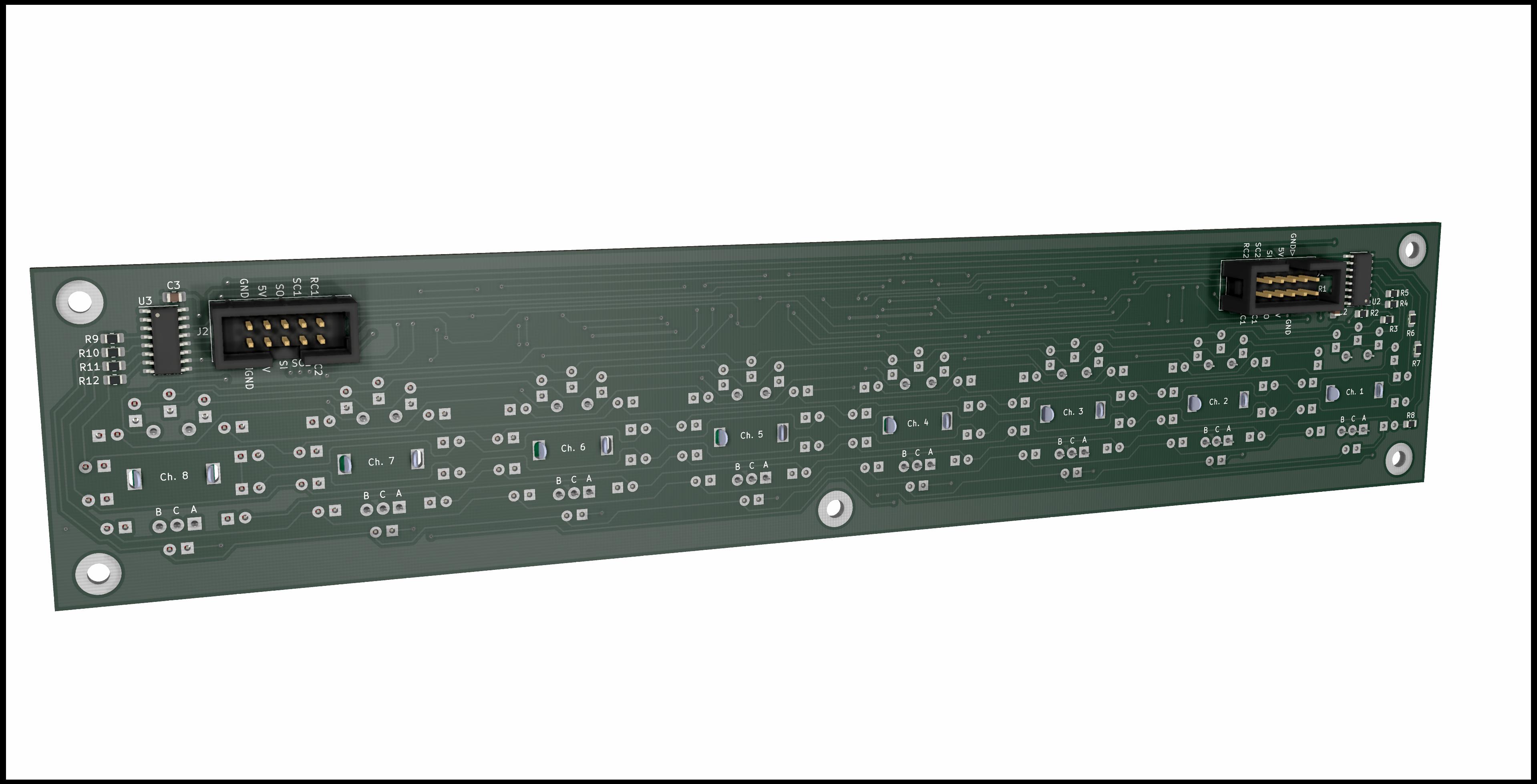
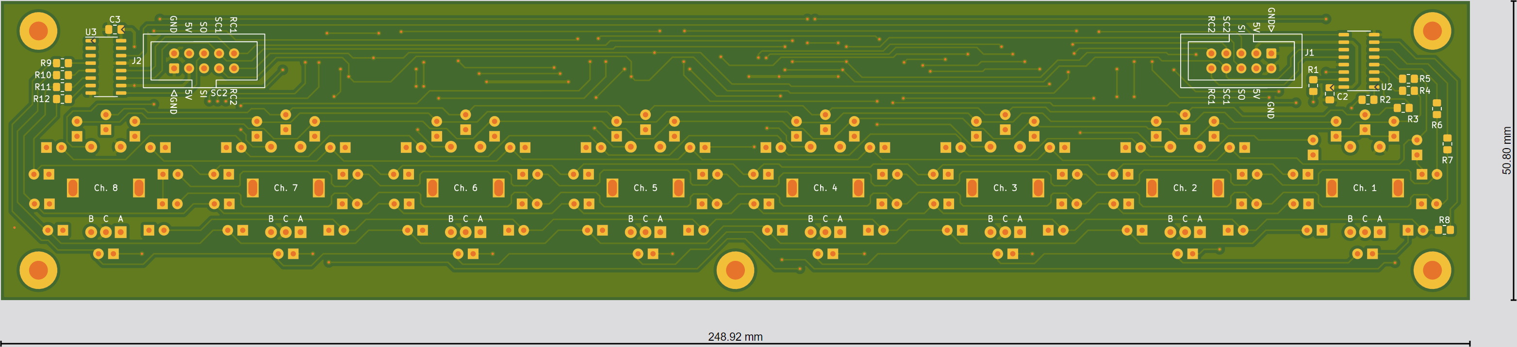
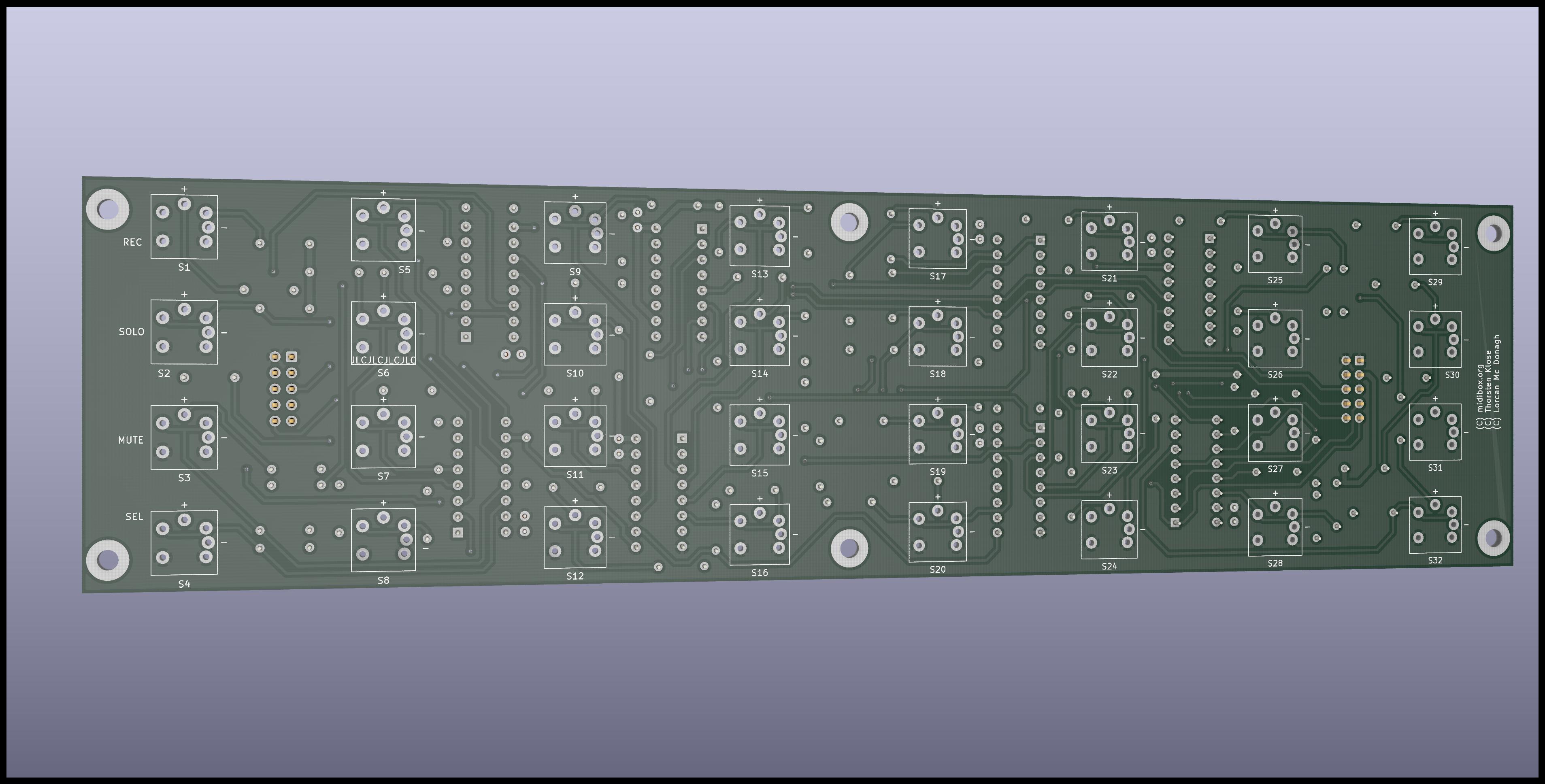
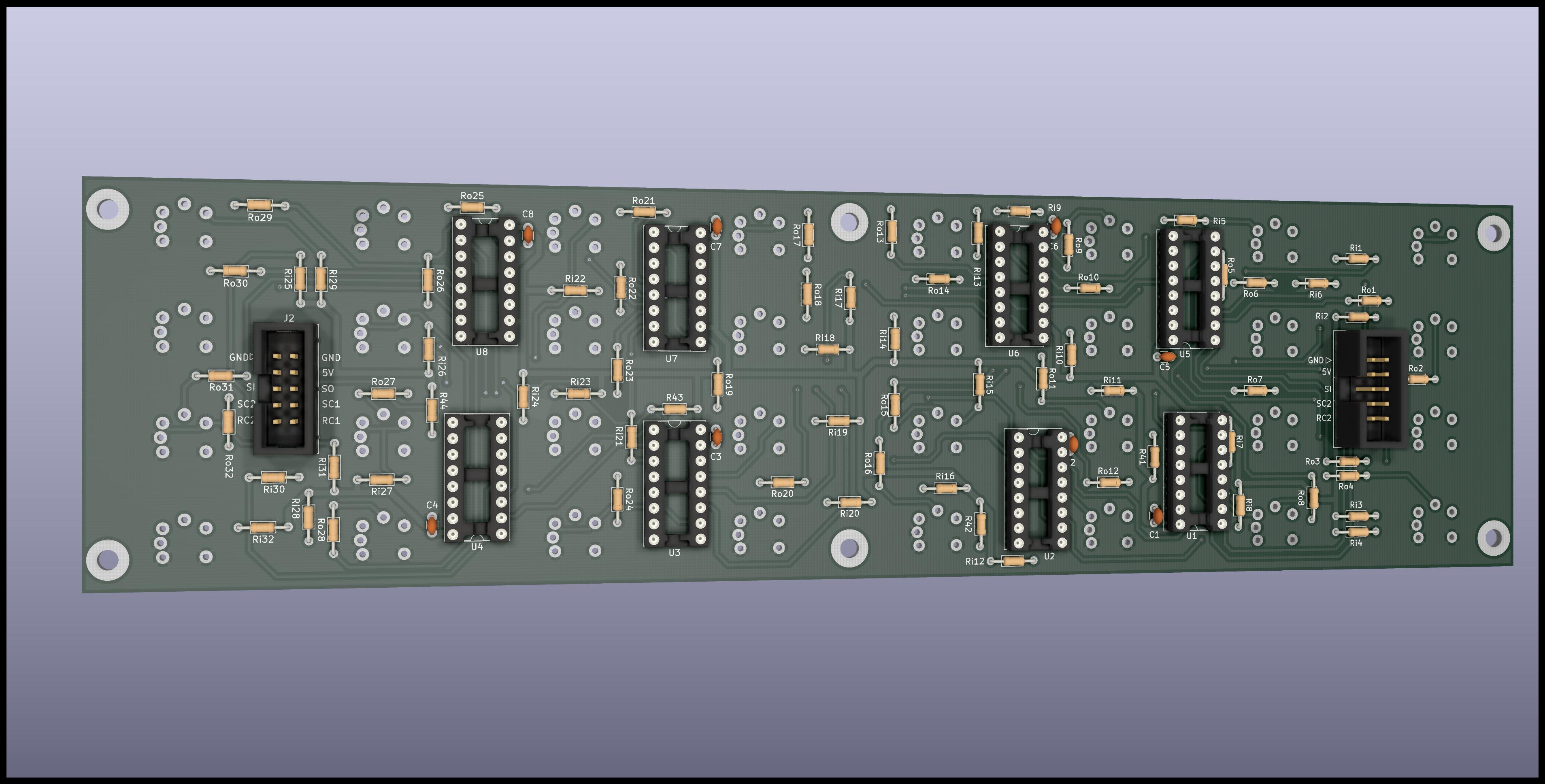
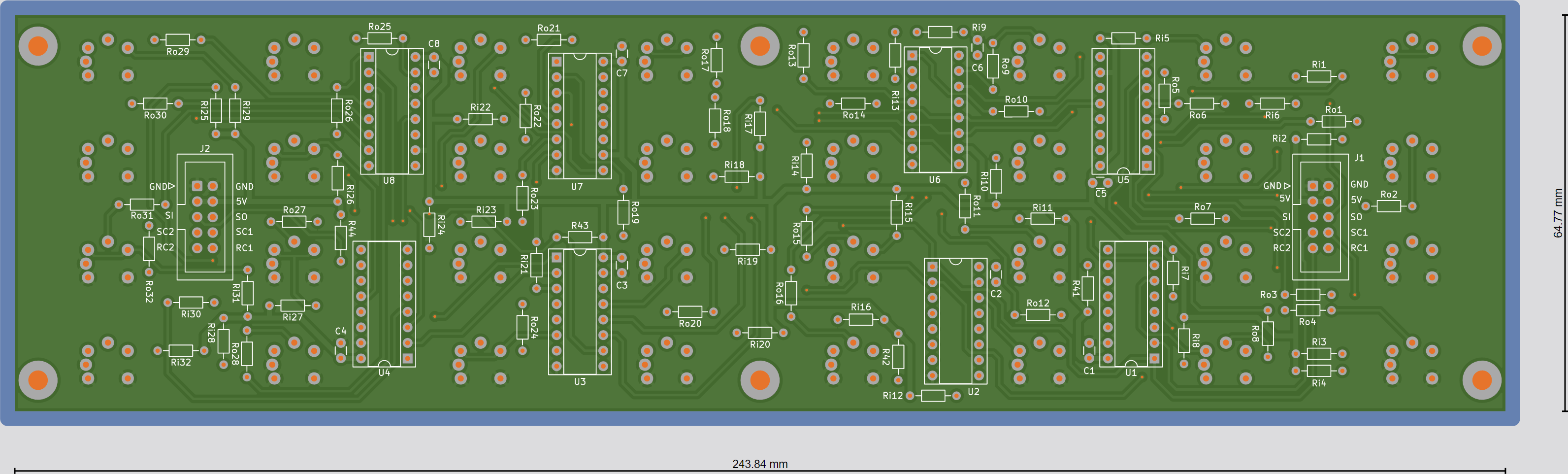
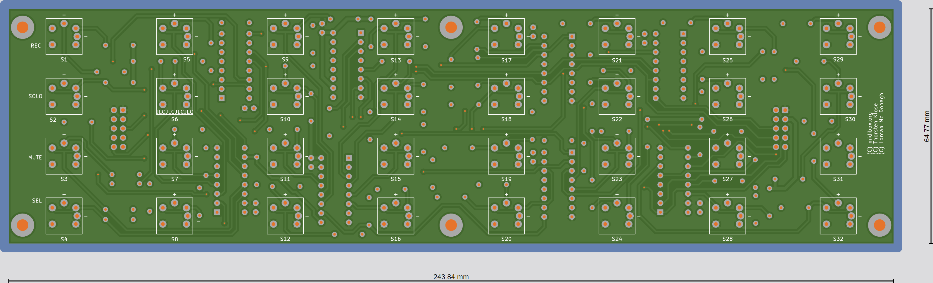
Hi,
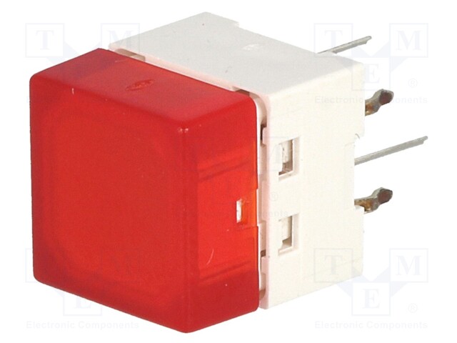
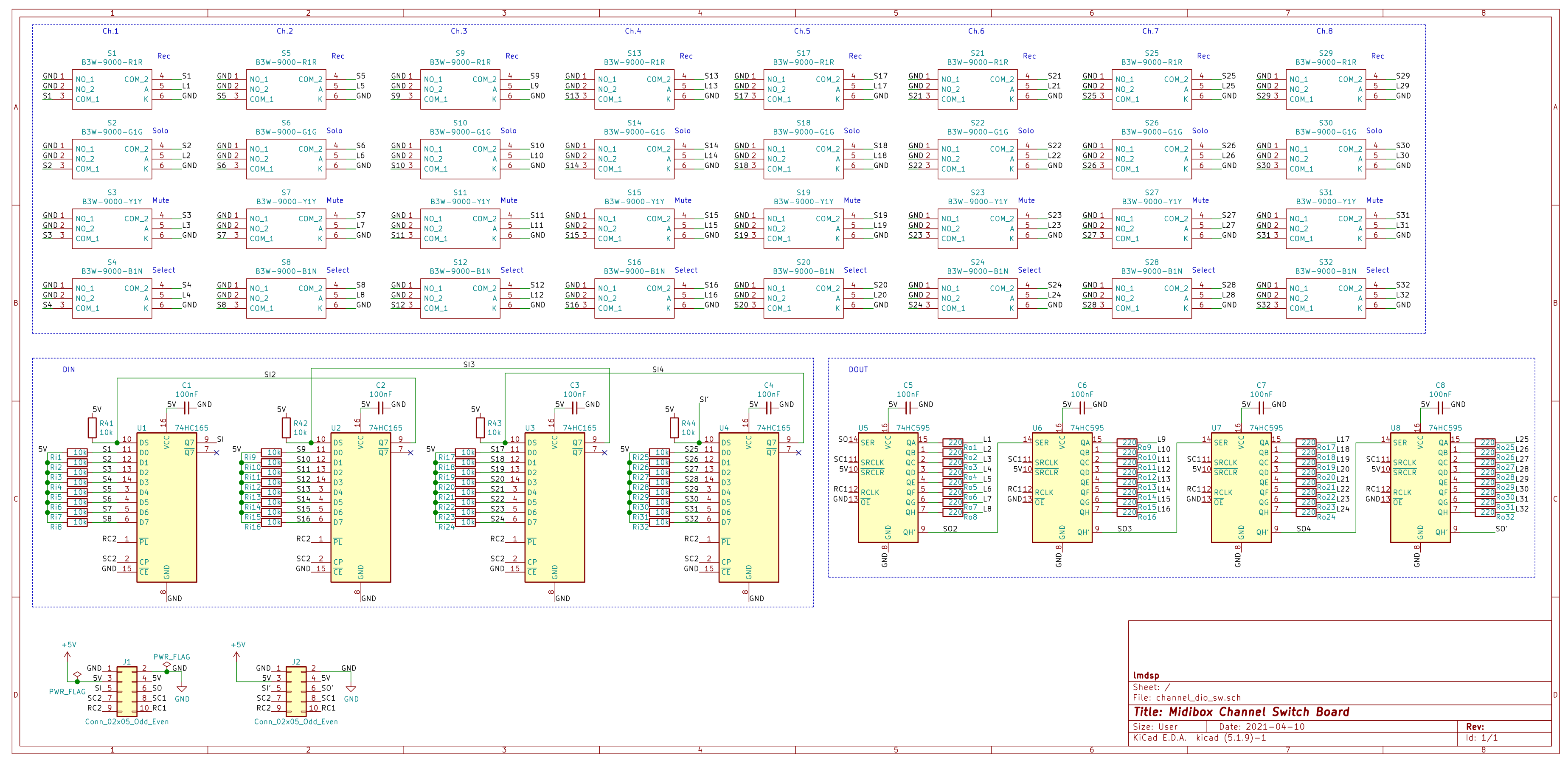
I've designed this PCB in KiCAD to hold 4x8 Omron B3W-9000 illuminated switches, as well as integrated DINX4 and DOUTX4.
Price vary quite a bit depending on the distributor, but in the EU I found them at ~2€ each here. The quality seems really quite good, and you can insert a printed transparent label to indicate function.
I've used completely separate lines for SI/SO, SC1/SC2 and RC1/RC2 as I understand this is the recommend way to reliably chain modules together in series, in order to not to mess up the timings. Can someone more knowledgeable than me please confirm this, and point out any potential mistakes before I send the files for production ?
I'll put everything on github when I've built the pcb and confirmed everything works as intended.


-
On 3/30/2021 at 12:42 PM, novski said:
Nice Work. I did same once. See: http://wiki.midibox.org/doku.php?id=fadercore_-_vlr-8odisp
i think i have some pcb still laying around.
Thanks ! Yes I've seen your work too, very impressive !
I want to make my own boards so I started with the simplest PCB to learn KiCad. It's quite a wonderful piece of software,it has evolved a lot since I last tried it. And it's looking even better in the upcoming version 6.
I've sent the PCB for fabrication yesterday, let's hope I didn't make any stupid mistakes ! -
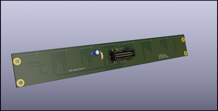
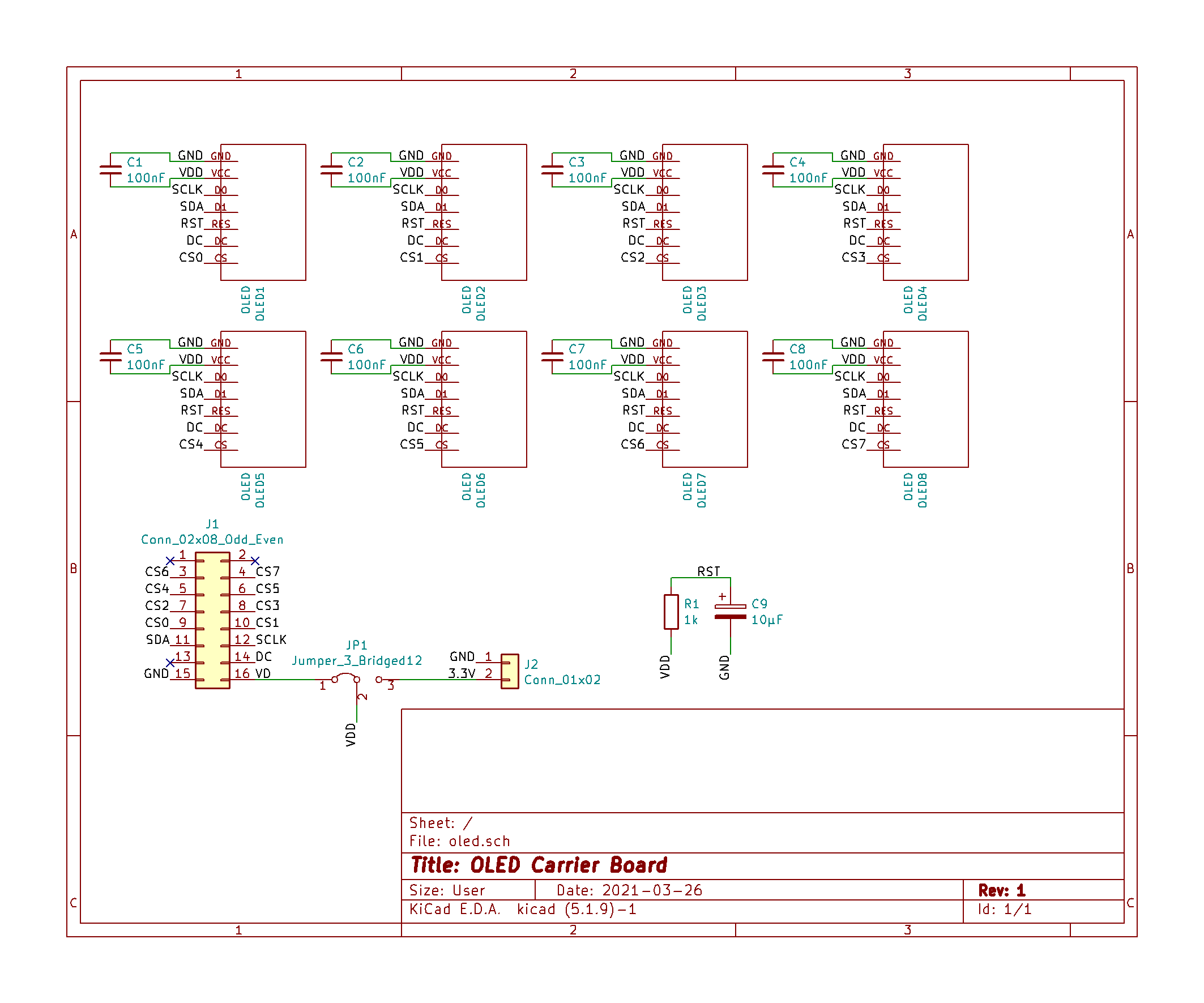
Updated the PCB, hopefully it's close to being ready for fabrication.
- Added decoupling capacitors (optional, just in case)
- Added external 3.3V option w/jumper selection
- Cleaned up traces etc
I'll put all the files on github when I've confirmed everyhting works as intended.
-
Found those which are 1x7, even better and only 0.27€

-
I'm going to use these from Reichelt which I will cut to 1x7.
They're 0.2€ so a fifth of the price !
This way if an OLED goes dead (they do after a few years), I can replace it easily.

-
On another note, I looked at current consumptions of various OLED's,
and according to this page, a 128x64 0.96” can pull 21mA at max contrast with all pixels lit.
As the STM32F4 board docs state, the integrated 3.3V regulator can only supply 100mA max.
I wonder if problems some people were having with multiple OLED's might be related to that.
So to be on the safe side and to avoid heating the poor little SMD IC,
I'm going to add an optional on-board 3.3V regulator or input.
-
15 hours ago, Phatline said:
i think you will need a the cap and resistor on reset for every display (they told me...dont know if necessery)
Thanks, but are you sure ? I distinctly remember reading @TK. saying only one is needed, at least for 8.
It looks like a simple RC cell, and I don't think the current drain on the Reset pin would alter the time constant.
-
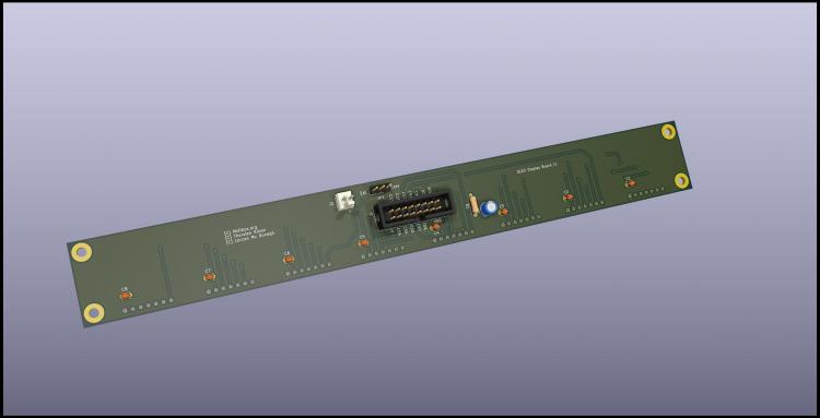
Hi,
I'm building a MCU type controller and I'm starting to design some PCB's for the various modules.
I'm planning to share them here so other users can use them if they want, if that's ok.
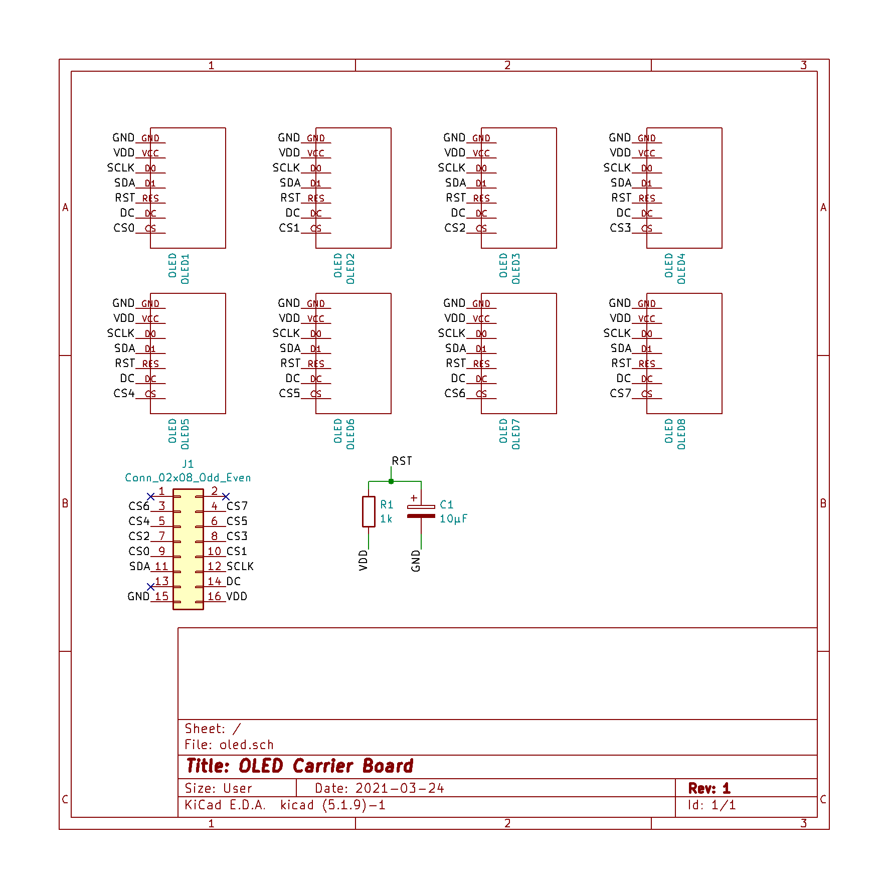
The first and simplest one is an 8xOLED carrier board to connect to J15A of the STM32F4 core.
Initial tests on a breadboard with 2 screens work fine.
It is my first time using Kicad and also designing a 2-layer board, so I'd like to get some feedback before sending them to the fab house.
- OLED's are 0.96'' SSD1306 4-wire SPI type
- Mechanically the OLED's are plugged into 1x7 sockets
-
Each 'channel' is exactly 1.1 inch wide. It leaves a little wiggle room between the screens,
and should allow the case too be quite compact -
I remember seeing another schematic with added 100nF decoupling caps, but they're not on Thorsten wiring diagram,
so I'm wondering if I should add those
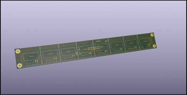
NOTE: I'm going to extend the board to avoid having the holes running under the OLED's.
-
You're right I missed this point.
According to this and this https://github.com/OLIMEX/MOD-OLED-128x64/blob/master/HARDWARE/MOD-OLED-128x64.pdf and this https://www.olimex.com/Products/Modules/LCD/MOD-OLED-128x64/resources/ER-OLED0.96-2_Manual.pdf the PCB is wired to configure the chip as I2C
But changing I2C to SPI mode only requires to change one connection (pin BS1) from high to low, so I guess just a little soldering + wire would do the trick
-
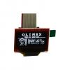
I just saw this https://www.olimex.com/Products/Modules/LCD/MOD-OLED-128x64/open-source-hardware
It's a 128x64 display with PCB and integrated connector for 5.5€
I haven't ordered any myself (yet) but I thought this might be of interest to the community
Cheers,
Lorcan
-
Dear Forum members,
in the meantime I got my first prototype PCBs for my MBLC.
After many sleepless nights I succeeded to get it running, I am very happy!
In this post I just want to refer to the topic of this thread, the MF V3 module and its implementation.
Since I´m an absolute beginner to Midibox I write this from a novice point of view...
The design of my PCB I posted earlier has a mistake but I fortunately figured it out before I had it fabricated so now it´s perfect. The power for the Motorfaders comes from an external PSU (around +10V), the +5V for the Logic comes from J11 of the Core8 PCB. Just connect "+5V" and GND of J11 on both boards (Core8 and MF V3).
Connect MIDI IN and Out (J13 and J12) of MF V3 to your MIDI interface and start MIOS Studio on your PC. First change the ID of your PIC to 1 (if it´s not done yet), then upload the newest MIOS on the PIC, thereafter upload the MF V3 application. Now with the integrated Calibration Tool of MIOS Studio you can, well, calibrate your faders, but even more important, set the MIDI merger to "Midibox Link Forwarding Point"!
Now disconnect the MIDI OUT to your interface but connect the MIDI OUT of the Core8 to your interface. Connect "MO" of J11 on MF V3 to "MI" of Core8 (which ID is 0). Now you have to set the Core8 as the "Midi Link Ending Point". I thought it could be done by changing the main.inc within the MBLC application:
;; initialize the integrated MIDI merger
movlw MIOS_MIDI_MERGER_MBLINK_EP
call MIOS_MIDI_MergerSet
But this didn´t work for me. Instead I had to run Serge's MIDIbox64e Editor and do the setting there. Well, at least it works now...
In the end the chain looks like this:
MIDI OUT Interface -> MIDI IN MF V3 (ID1); "MO" MF V3 -> "MI" Core8 (ID 0); MIDI OUT Core8 -> MIDI IN Interface
The advantage about the two different IDs is that it´s possible to upload apps on the Core8 without affecting the MF V3. Still you can to run the Calibration Tool (select ID 1) for the faders. In this chain it´s not possible do an upload on MF V3 though, but once it´s running you won´t do that anyway...
I hope this might be of help for someone, since it took me lots of trial and error to find out, but it was definately worth it.
Thanks everybody, especially TK of course!
Emre
Hi, that's a nice design you have there, congratulations !
May I ask where you were able to source the 2x55 char lcd from and how much you paid for it? These seem to be very rare beasts ...


Frontpanel Services on Europe - Mainland + UK?
in Parts Questions
Posted
$90, wow that's amazing. I prefer to favor local production but at this price it's quite tempting.
Does that include shipping ? Also import duties (VAT + processing fees) might bump this price quite a bit.