

Tanstaafl
-
Posts
268 -
Joined
-
Last visited
Never
Content Type
Profiles
Forums
Blogs
Gallery
Posts posted by Tanstaafl
-
-
again, too dang kool !
I have all of the parts for this, think i will burn the pcb this weekend and give it a try,
Thanx Prof !
-
oh, duhhhh
-
Too Dang KOOL!
specs / schematics?
-
Neat !!
-
sooo kool !
now all u have to do is hack MIOS and make the lcd's display cyrillic.... hee hee hee
great looking box, bud.
gb
-
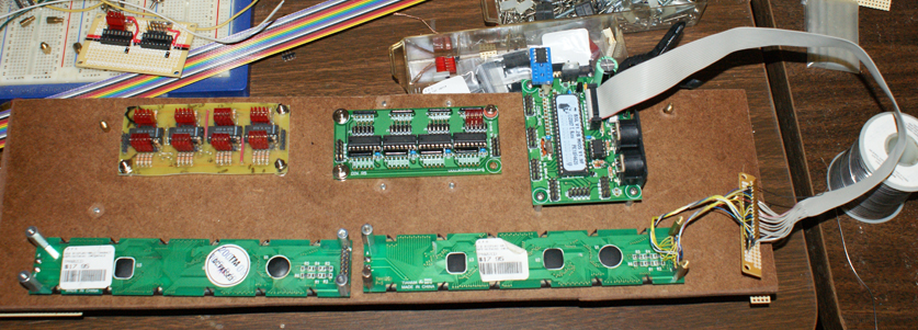
Here is the next incarnation.....still some bits to go... but getting there
gb
-
eventually I will have all of the Din's and Dout's connected... but they will have to be separate drawings... unless I can do it in flash or something to get all the layers.... like I said, a work in progress. The original is done with photoshop so I have layers to work with.
p.s. I have not taken the test, but I don't believe fish drink. Respiration / osmosis? might take care of the h2o requirement?
gb
-
Here is a work in progress for my front panel interconnections to DinX4 & DinX2 modules
only the first is connected, taking my time with this....
-
p.s.
Thanx Stryde!!!!
-
ok, sherman set the wayback.....
I messed with walkmen clones,
old 8-track hardware.... been there done that... it's REDICULOUSLY expensive....
The Mellotron dudes got it correct the first time... a standard capstan that spins everything at the same rate.. but the wear and tear...
then I bought my first Kurzweil in a pawn shop... old K2000S maxed out the RAM and OS. About 500 USD.
..... that's kinda when I gave up on the tape thing.... it has tickled my fancy a few times since then... but I do find it to be much more satisfying to just spring for the pro samples... and put em in the K2000.
my 2cents
-
BTW, we survived IKE !!! no power or internet for 5 weeks, thank you very much.... I can't believe this in Houston!!
anyway, nice to be back
c ya
-
I've been working on a DIY Mellotron since the 70's...... grrrrrrr
-
uhhh, heat it up with your soldering iron and pull the wires away.... then use a hobby knife to scrape the leftovers off the board, then drill the holes that got filled up?
i use that procedure on a regular basis... if there is a better one, lemme know!!
gb
-
these are personal preferences, at this point, your questions are about esthetics.
everybody has a different vent on what looks good.. or might be usable as an interface
good luck with your particular interface !
gb
-
E not CS... i think
-
the CS line on LCD 1 is hooked normally to the Core with the ribbon cable, the CS on LCD 2 will be connected to.... RC on J10 of the Core? The loose wire, not quite sure what I will do to fasten it down.. but that shouldn't be rocket science. (who/m/ever invented hot glue should get the Nobel Prize!)
that's my story and I'm sticking with it :)
-
YeeHaw !!
Thanx TK
-
I am using the same idea InDeep, however I am using wire wrap to interconnect the LCD's together and then into a pin block that is soldered to the ribbon cable going to the connector on the Core.....here is a cheesy pic but you get the idea. And of course, I have not connected the second LCD as of yet.
good luck,
gb
-
hmmm, just tried this a couple of times on my mac and got the following:
MacPro:MidiBoxStuff ggb$ svn co svn://svnmios.midibox.org/mios
svn: Can't connect to host 'svnmios.midibox.org': Operation timed out
Not sure if i beeez doing something incorrectly, followed the 'if you run Linux/MacOS then svn is (mostly) installed.
Opened terminal in my midibox directory/folder and got the above message.
any ideas midibudz?
TIA
gb
-
Thank You, TK !!
-
I have thought about that also, but have not dissected my switches to see if I can replace the LEDs.
I think I got the idea of bolting the perfboards from the pix that TK put up on the web.
My point of difference, I then attached the perfboard to 1/4" hardboard (with 1/2" plastic spacers) to firm up the 'floppy' way perfboard goes together. I will drill holes in the hardboard to allow wires to pass through, and mount all the PCBs on the underside of the hardboard. That way, it is only a rack mounted panel, without an enclosure.
good luck with your project !!
gb
-
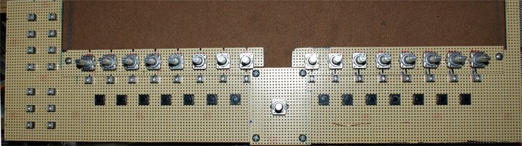
here is the control surface so far.... wondering if I will need some other button caps for the black switches... hmmm need to look.
-
yeah, that was my problem....
luckily, i am a pc tech so have pc's also. I grabbed the image in 'FrontPanel' then saved it as a gif file. pulled it into photoshop on my mac and scaled it to fit a 19 inch rackmount. at least the dimensions are correct... it's not pretty, but if you would like a copy, i would be happy to email it to you. pm me.
good luck,
gb
-
yes, the midi ports on the Core.
took me a few minutes to get MiosStudio configured correctly, but after that, everything was hunky-dorey
custom keyboard/controller to control arturia's jupiter 8v vsti?
in Design Concepts
Posted
I have made 2 arturia control surfaces with mbhp.
MMV and miniMoog.
both work great.
good luck