

Wilba
-
Posts
3,310 -
Joined
-
Last visited
-
Days Won
2
Content Type
Profiles
Forums
Blogs
Gallery
Posts posted by Wilba
-
-
Excellent work, TK!
Since two data pins of the LCD are allocated by the CAN peripheral, the LCD has to be used in 4bit mode. This is no performance loss, as the LCD benchmark turned out. The 18F4685 variant of MIOS always accesses the LCD in this mode
You can programmatically turn on 4-bit mode in the application's initialization, but it's not a configuration bit in the PIC ID header. Can you add a bit in the PIC ID header so MIOS can use 4-bit mode on any PIC, not just the 18F4685? (or use 8-bit mode on the 18F4685, if one didn't need CAN?)
This hardware change has just brought to my attention that I could use a cable with four less wires and would like to start doing that now! ;D
-
can you put the resistor network in the wrong way?
Probably not ;)
The fact that have two cards seems to make me believe it is something in the d-out cards..
hmmm... I might just have to buy two more and see what happens.. since the core seems to working fine with my other box well expect for the 18 midinote. The funny thing is that the once a plug in the orginal core back into the older box... it has no problem using note 18... is there a default numbering in the new mois spec that is for resting? Because the orginal core is running the previous version of mois.
thanks
As far as I know, the specs on the DOUT have not changed, "bypass capacitors" have been added to the schematic and newer PCB revisions, but it's still "compatible".
There was a change in the wiring of the Core with MIOS 1.7
http://www.ucapps.de/mios_v1_7_hardware_mods.html
This probably is unrelated, but you did mention different versions of MIOS, just confirming you are aware of it.
It is really strange that one Core resets when it gets note 18, perhaps narrow down why that happens first, i.e. does it happen even when there is no DOUT connected?
-
I saw that video a while ago and wondered why you had never posted here... not even some photos of your finished MIDIbox, which looks really cool from the video.
As for your DOUT problem, start with checking the wiring between Core and DOUT module... test a pin on the PIC is actually wired to pin(s) on the shift registers.
Then maybe try this? http://www.ucapps.de/mios/srio_interconnection_test_v1.zip
expect for some reason the box was resting itself when midi note 18 was turned on??But this sounds like the shift registers are actually working, and when MIDI note 18 is turned on, the shift register output pin that should go on is actually shorting to ground. Hmm...
Try unplugging all the resistor networks and testing if the shift register outputs go high/low as expected by your firmware (using a multimeter). See if the resetting problem still happens with the resistor networks unplugged. Also, test each DOUT module individually.
I suppose it's unlikely you've put the resistor networks or the shift registers in the "wrong way" ;D but check that too.
Finally, you might want to check pins 10 and 13 on each shift register, check they are connected to +5v and ground respectively. If you've soldered a PCB from SmashTV, it's probably not a PCB fault, maybe just a bad soldering joint?
-
It would be nice to have a couple of single bit configurable switch controls, and maybe one 2 or three bit control for filter selection built into the voice structure of V2....
Reminds me of another wish I had...
My wish for the V2 patch format is that there is space reserved for future features coming from TK as well as some space that is totally user-specific and usable by people adding their own features. The CMOS switch control is a great example... as what you're switching might be filters or effects or a noise gate... and all people need is a place to store those bits that won't cause any compatibility issues with the preset patches or with other people's patches, with patch editors or patch loading/saving utilities etc.
Another good example is a "Volume" modulation target, complete with an 8th row of LEDs in the mod matrix, that's what I really want, whether TK puts it in or not ;D so it would be really nice if there was space in the patch format to store those eight bits.
-
If it's possible, try mounting the switches onto their own board, and then put spacers between the two boards.
However, if you've got a lot of individual switches and not a lot of grouping, this probably won't work so well.... maybe even invert the idea, mount all your switches to one board and then mount the taller components behind it, poking through some holes/slots.
-
Wilba's MIDIbox Debugging Service
Debugging your MIDIbox from across the globe with only the powers of his own mind!
If you have found this service worthwhile, feel free to
 an amount that reflects how happy you are that your MIDIbox now works!
(Note: donations are not tax deductible)
-
The MB-SID should boot up in the "Top Screen":

and turning the rotary encoder should change the patch. You don't need to press the menu button.
You might have the wiring of the buttons and encoder wrong somehow, or maybe you're missing a resistor on one of the DIN inputs, or missing a resistor to "terminate" the chain of shift registers (see R33-R36) or maybe even forgot to ground the CLI pin (pin 15) on the shift registers. (OK all this suggests you hand-made your DIN module instead of using a PCB).
-
I've changed patches without an LCD before, the lack of LCD is unrelated I think, but makes debugging harder.
It has happened to me before that by plugging in a BankStick for the first time, it got stuck on Bank H, patch 128... that bug should have been fixed already :-)
The 6 tone tune might be the Zelda patch which is patch 128, again, sounds like it's stuck on the last patch. The "startup" tune is a very short rising tone, less than half a second.
I suggest trying to change the patch using MIOS Studio... the virtual keyboard can change the patch (see "Program" spinner). Also try switching to Bank A, from the spec, sending:
F0 00 00 7E 46 <device-number> 0B <bank> F7
will change the current bank (you'll probably just use "F0 00 00 7E 46 00 0B 00 F7")
Switching to Bank A will store in the PIC that you're using Bank A, so next time it should boot in Bank A (in case it was doing wierd things and stuck in a non-existent bank!) Same with patch number, it should remember what patch you used last time when you boot it.
I would have thought the default patch would remain until changedThe "default" patch is stored in the PIC, and it's no longer accessable after you plug in a BankStick.
-
Will the Aout run on 9v dc? The psu diagram shows +-12v. I hope it can be used, this way looks good!
I don't really know... I suppose in theory you can make the AOUT work with +-9v but the voltage output range is also reduced, so no good if you're driving gear that needs -10v to +10v.
I don't think digital noise is a problem because I don't get any with my SIDs, where digital noise is more noticeable than with AOUT... i.e. for the SID box the 9v (analog) and 5v (digital) grounds are joined at one place, close to the power socket. So similarly, splitting AOUT power from Core power at one point as near to the transformer as possible should be fine.
-
I would also suggest 22nF capacitors for the 8580 and 6582 instead of 6.8nF.
Seach for other posts about this topic, in short, 22nF will give a better frequency range with less stepping at the low end.
-
I will have to disagree ;D
Isn't 1 amp of 5 volts enough for two LCD backlights and a Core?
My "black" C64 PSU brick is rated at 1.5 amps for 5V and 1 amp for 9V AC.
There are two "windings" on my PSU's transformer, though I haven't tested it, I'm assuming they're identical, both delivering 9V AC, one 9V AC output goes direct to the plug, the other goes into a 7805 regulator with a HUGE aluminium heatsink.
In my MB-SID v2, I rectify the 9V AC into 9V DC and join the ground with the 5V DC ground, and have had no problems with it at all.
So I don't see any problem with using a half-wave rectifier on the 9V AC and getting +/- 9V DC for your AOUT, and the 5V DC to power the Seq, and joining the grounds together at a central point (you want to keep your AOUT's ground well away from the digital ground of the Core and other modules). You can effectively treat the 9V AC and 5V DC outputs as separate, as if they were coming from two separate AC adapters.
Something like this ought to be adequate (taken from the PAiA ribbon controller circuit):

That's the general idea - feed your AC into two diodes so that your matching pair of positive and negative voltage regulators each get the positive and negative "phases" of the AC power. Each regulator only gets half the power, so the current output is half (probably less) for each regulator, i.e. for 1 amp 9V AC, you can get +9V at ~500mA and -9V at ~500mA. My advice is to increase the capacitors C6 and C7 to be big, like 1000uF - 2200uF perhaps... this will ensure there's enough voltage stored in the capacitors during the gaps in the phases to supply the regulators. Remember to use POWER DIODES not those tiny signal diodes, you want the big black ones that can handle the current.
The beauty of this idea is that you can use any old AC adapter that outputs AC (not DC) and get a symetrical DC supply out of it, without needing to buy a transformer and wire it to mains power.
I can't tell you if this is better or worse than a symmetrical PSU built like the one presented here, but it should do the job and will be easier to construct.
-
No, it was US$80 shipping, it is international courier only. >:(
Thanks for the offer, nym! Much appreciated. PM me and I'll send you some dough via paypal.
-
Yeah, cheap, but only ships to Australia by UPS for $80. Bugger.
Any chance you can buy some on my behalf and post it to me?
-
bill: With a step B control surface, you can hold down one SID button and then press the menu button and it toggles playing a note on that SID.
-
I'm currently trying to make my own ribbon controller but haven't found a good material to use. In my searching, I came across Velostat, and if it's the same stuff in which my PLED display was packed, then it might just work well... but haven't found a supplier.
-
Well, Winstar and OSD (One Stop Displays) still have them on their website. There's obviously still high demand for character displays, even long after other kinds of displays have been available, so perhaps it's just one manufacturer that's discontinuing for some reason, and Crystalfontz and Matrix Orbital are too lazy to switch to a new supplier.
If there really was low demand for PLED/OLED, why would manufacturers be developing new products that use it?

One Stop Displays (OSD) is proud announce the latest product reliability information for OLED displays..
Winter Park, FL -May 5, 2006 -- One Stop Displays (OSD) releases the latest news from OSD is their new 100k Hr OLED display offerings. This new lifetime advancement will allow new applications to consider OLED technology. The advancement is limited to monochromatic yellow display products. The lifetime is calculated for operational hours from initial to half-brightness at 25*C.
The new feature product applying the latest material enhancements is the OSD5664ASYAT02, 256x64 monochrome OLED. This display is perfect for 1RU rack mount designs, automotive, avionics, and a full range of applications. The display can support 7-bits per pixel PWM for 'grayscale' image depth. The display offers compatibility with parallel, I2C, and SPI interfaces via a standard ZIF-style 0.5mm pitch flex interface. The display is a relatively large OLED display offered at 2.8? @ 84.0 x 25.8 x 2.2 mm outline dimensions.
2.2mm thick!
-
You might want to check out the Hypnocube, an interesting project using RGB LEDs:
But that's a bit off topic...
For maximum speed and performance, use 108 individual DOUT outputs. This is also the maximum number of 74HC595 chips you'll need too, but since it's a coffee table, size isn't a critical factor. Each colour can be pulse width modulated with a minimum pulse width of the shift register update period, i.e. 1ms. It also means that each LED can be fully on and be at maximum brightness.
So if you want to optimize the hardware, then you could use a matrix and multiplex the outputs. Maybe 6 is a good number of "columns" in your matrix, so you'd use 6 DOUT outputs (through a darlington array) to sink the 6 "columns" of 18 LEDs (6xRGBs), and you connect the anodes of each "column" in "rows" to 18 DOUT outputs. The only problem is that by multiplexing, you'll have less "grain" in your duty cycle.
EG. in the first scenario, a 1ms update, with a max of 20ms (to avoid flickering, 1ms on/19ms off, etc.) gives 20 "shades". In the second scenario, the update might still be 1ms, but there's another 5ms gap where the other columns are active, so it's like a 6ms minimum pulse width. Divide that into 20ms and you've only got 3 "shades". You can cut down the number of matrix "columns" to get a smaller minimum pulse width, perhaps using three columns is optimal, I don't really know...
I've probably rambled on enough ;D the short answer is: just use 108 DOUT pins, might be a bit more expensive and more to solder, but will be easier to code and work better in the long run.
-
I bought some of these knobs from ALBS for my MB-SID, and some other ones for the MB-Seq.
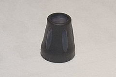
I can confirm that they do fit perfectly to a plastic 6mm/4.5mm shaft like the encoders from Voti. (My encoders aren't from Voti, but they're from the same manufacturer). Expect long delays between emails from ALBS, but they do eventually deliver. However, they're probably not the best ones for a MB-Seq, a bit too big at the base, it might be better to order some of the narrower ones with the same sized shaft hole (the ones on TK's MB-Seq are also from ALBS, quote from parts list: "12 x "DK13-164 black-soft", 4 x "DK13-164 gray-soft", 1 x "DK38-144" from Albs"). I got the very narrow ones, "albs P/N 860006- -Drehknopf DK10-150 A.6/4,5 AT:13,5mm schwarz" and they also fit nicely to my encoders, as would any of the ALBS knobs with "A.6/4,5" in the description.
Hope that helps you ;D
-
Why so many regulators?
FYI, the "C64 Brick" has just one 7805 in it, with a massive heatsink, as it's regulating the second 9v AC coming out of the transformer, the first 9v AC goes direct to the plug.
Following the experiences of others, including myself, who have reused the C64 PSU, that one 7805 should be enough for the 5v supply to four Cores, four SID modules, one backlight LCD and the required DIN and DOUT modules, plus all the LEDs.
Also, you don't need that big a capacitor on the SID module, or even on the Core... these are big in case you supply those modules with AC and need to convert it to DC via a bridge rectifier and regulator. You can put those bits external to your stacked modules. See this: http://www.ucapps.de/mbhp/mbhp_4xsid_c64_psu_optimized.pdf and consider the 7805's removed from the Cores, each Core gets its 5v from a common supply, the one out of the C64 PSU. You can take that idea one step further and take out the regulators on each SID module, supplying each from a common 12v supply external to the modules.
-
If buttons 1-4 are working, then DIN->Core connection is OK, the fact that the non-working ones are all on one side (and the other side works) might mean you're connecting those components through the the ground (Vs) pin on J4, but that pin isn't connected to ground at all. Or, the break is higher up the wire, i.e. in the wire, or nearer the components. Test all the pins that should be ground, best way is probably to test for +5 volts and move the black probe to different points that should be at ground (so you see a change on the multimeter instead of always being zero!)
-
Zoink! Thanks mate... ;D
-
Yeah I meant DOUT. ;D
-
You don't always need transistors, the 74HC595 outputs can sink (just) enough current to light a column of LEDs. If you prefer to have the LEDs brighter, use transistors, but also remember you'd need to invert the output... i.e. if you connect the base of a BC547 to the DOUT pin (with a 1k resistor), then the collector will sink current when the DOUT pin is high. So only one of the outputs should be high at a time, instead of one of the outputs being low.
The newer DIN DOUT module boards from SmashTV can have a darlington array chip fitted instead of the resistors (i.e. a chip of eight high-current transistors).
-
albs.de has them.
MIDIbox of the Week (MIDIbox SID of Jack)
in MIDIbox of the Week
Posted
These knobs are the same ones used by Waldorf.
I've bought these knobs from ALBS.de, refer to previous discussion:
http://www.midibox.org/forum/index.php?topic=8190.msg56745#msg56745